
Experimental investigation of the electromagnetic effect and improvement of the plasma radial uniformity in a large-area,very-high frequency capacitive argondischarge
2021-05-22 07:01:12DaomanHAN韓道滿ZixuanSU蘇子軒KaiZHAO趙凱YongxinLIU劉永新FeiGAO高飛andYounianWANG王友年
Plasma Science and Technology 2021年5期
Daoman HAN (韓道滿), Zixuan SU (蘇子軒), Kai ZHAO (趙凱),Yongxin LIU (劉永新),3,?, Fei GAO (高飛) and Younian WANG (王友年)
1 Lab of Advanced Space Propulsion and Beijing Engineering Research Center of Efficient and Green Aerospace Propulsion Technology, Beijing Institute of Control Engineering, Beijing 100190, People’s Republic of China
2 Key Laboratory of Materials Modification by Laser, Ion, and Electron Beams (Ministry of Education),School of Physics, Dalian University of Technology, Dalian 116024, People’s Republic of China
Abstract We performed an experimental investigation on the electromagnetic effect and the plasma radial uniformity in a larger-area, cylindrical capacitively coupled plasma reactor.By utilizing a floating hairpin probe,dependences of the plasma radial density on the driving frequency and the radio-frequency power over a wide pressure range of 5–40 Pa were presented.At a relatively low frequency (LF, e.g.27 MHz), an evident peak generally appears near the electrode edge for all pressures investigated here due to the edge field effect,while at a very high frequency(VHF,e.g.60 or 100 MHz), the plasma density shows a sharp peak at the discharge center at lower pressures, indicating a strong standing wave effect.As the RF power increases, the center-peak structure of plasma density becomes more evident.With increasing the pressure, the standing wave effect is gradually overwhelmed by the ‘stop band’ effect, resulting in a transition in the plasma density profile from a central peak to an edge peak.To improve the plasma radial uniformity,a LF source is introduced into the VHF plasma by balancing the standing wave effect with the edge effect.A much better plasma uniformity can be obtained if one chooses appropriate LF powers, pressures and other corresponding discharge parameters.
Keywords: electromagnetic effect, plasma radial uniformity, very-high-frequency capacitively coupled plasmas
1.Introduction
Recently, researchers and semiconductor equipment manufacturers have paid much more attention to large-area capacitively coupled plasmas (CCPs) [1, 2] driven at very high frequencies (VHF) (usually much higher than 13.56 MHz).Herein,increasing the electrode’s area aims to meet the need of processing a larger-area silicon wafer,and thus reducing the cost per chip.Meanwhile,a higher driving frequency can produce a higher plasma density, and consequently, a faster material processing rate, while offering a lower ion bombarding energy.However, along with the increase of the driving frequency and the electrode area, the standing wave effect comes as the excitation wavelength approaches the electrode’s size, and the skin effect appears when the plasma skin depth becomes comparable to the electrode spacing.Besides, the edge effect also plays a vital role in affecting the plasma uniformity.These three effects are collectively known as the electromagnetic (EM) effects that will cause severe plasma non-uniformity, which produces a negative effect on the material processing.Therefore, there are increasingly intensive theoretical and experimental studies on the EM effects in VHF large-area capacitive discharges [3–38].
By analytically solving the full set of Maxwell’s equations in a uniform slab model, Liebermanet al[6] firstly showed some cases where the skin effect and the standing wave effect play essential roles in VHF capacitive discharges in 2002.Later, a self-consistent transmission line model coupled with the Child law of the sheath and the particle and energy balances was deduced from the EM fields by Chabertet al[7,8].It was found that capacitive discharges experience an E–H transition as the radio-frequency(RF)voltage is raised.This phenomenon was in good agreement with the experimental results obtained by Perretet al[9].After that,Leeet al[10]coupled Maxwell’s equations with a set of fluid equations in a two-dimensional axisymmetric model, and observed the so-called ‘stop band’ phenomenon at higher pressure and a higher frequency i.e.200 MHz.This effect was later observed experimentally by Liuet al[11], due to the fact that the EM waves are highly damped as they are propagating from the electrode edge into the discharge center.In the meantime, Mussenbrocket al[12] verified that the results obtained by the electrostatic approximation might not be correct due to considerable skin effect in the regime of high plasma density, particularly when the gas pressure is low.A modified fluid model was adopted by Raufet al[13],and modeling results showed that the plasma density peaks off-axis when the electrostatic effects are dominant, while it peaks at the electrode center if the standing wave effect is significant.With the fluid simulation,Zhanget al[14]observed distinctly different plasma characteristics between the results obtained with an electrostatic model and an EM model, and the difference becomes more significant at higher frequencies and lower RF voltages.More recently, numerical simulation with high-resolution computational meshes[15]revealed the presence of higher harmonics that are strongly correlated with the occurrence of a center-peaked plasma density profile.
Besides, some experiments have been implemented to study the EM effects.By using a probe matrix system and the retarding field energy analyzers, Perretet al[9, 16] found a higher and non-uniform ion flux at a higher frequency of 81 MHz,but a lower and uniform ion energy compared to that at a lower frequency (LF).Through a B-dot probe, Ahn and Chang [17] observed a significant inductive electric field at the radial edge, which causes severe radial inhomogeneity of the plasma density.Similarly, the distribution of voltage amplitude along the electrode in VHF capacitive discharges was found to be non-uniform, which is in good accordance with that of the plasma density distribution [18].The radial profile of the plasma density measured by Liuet al[11, 19]showed that the wavelength of the standing wave decreases as the RF power is reduced, and the standing wave effect tends to become pronounced at higher frequencies and lower pressures.Moreover, Milleret al[20] and Sawadaet al[21]showed evidence for the existence of higher harmonics when they did Fourier transform of the axial electric fields measured by a plasma absorption probe and magnetic fields measured by a B-dot probe, respectively.Recently, Zhaoet al[22, 23]designed a new-type B-dot probe circuit and measured the spatial profiles of harmonic magnetic field in a 100 MHz capacitive discharge.They found that nonlinear higher harmonics induce radial standing waves,resulting in center-high radial distributions of plasma density.
In order to suppress the EM effects and improve the plasma uniformity in large-area VHF capacitive discharges,some methods have been tried, such as the specially shaped electrode (i.e.the Gaussian-shaped electrode [24, 25], the stepped electrode[26],and the segmented electrodes[27–30]),the phase-shift control[31–34],and the external circuit control[13, 35].Sansonnens and Schmittet al[24, 25] found that plasma inhomogeneity caused by standing-wave effects can be effectively suppressed by employing a shaped electrode for a specific high frequency in a given reactor.By controlling the phase shift between two RF sources driven by the same frequency (100 MHz) in the experiment, Sunget al[31, 32]obtained a relatively good plasma uniformity.Later with a 2D fluid simulation model, Zhanget aland Xuet al[33, 34]verified that over a wide frequency range of 13.56–200 MHz,the phase-shift has a significant impact on the spatial distributions of the power deposition as well as the plasma uniformity.Also,by using a fluid model,Beraet aland Raufet al[13, 35] found that an appropriate adjustment of the external circuit, the electrode gap, or the addition of some electronegative gases can improve plasma spatial uniformity.Aside from the described methods above,Zhaoet al[36]found that a better radial uniformity of the plasma density can be obtained in dual-frequency CCPs by adjusting the voltage amplitude ratio of two high driving frequencies (90MHz+180 MHz).
It should be noted that most studies on the EM effects were carried out in reactors with relatively small electrodes,where the conclusion drawn will not be applicable for future industrial applications (i.e.450 mm in electrode diameter for the next-generation silicon wafers).In this paper, experimental investigation on the EM effects was carried out in a large-area CCP reactor(450 mm in electrode diameter)driven by three typical frequency values,i.e.27 MHz,60 MHz,and 100 MHz.We measured the radial profiles of the plasma density by using an in-house prepared floating hairpin probe,and the effects of the RF power, the gas pressure, and the driving frequency on the radial profile of the plasma density were studied.In addition, the LF source was added into the VHF plasma, aiming to obtain a better plasma uniformity.This paper is outlined in the following way.In section 2, the experiment setup, as well as the diagnostic method, is briefly described.Experimental results are presented and discussed in section 3.Finally, a summary is given in section 4.

Figure 1.Schematic of the large-area CCP reactor supplemented with a hairpin probe diagnostic system.Note that the single-frequency discharge case with the bottom electrode powered is solely shown here.
2.Experimental setup
Measurements were carried out in a large-area parallel-plate electrode cylindrical chamber (see figure 1).A similar chamber was described in detail elsewhere[36,37,39–41],so only a brief introduction is given here.The major difference of this from the previous one is that this chamber has a larger diameter of 800 mm and consists of two electrodes with an equal diameter of 450 mm [37].The purpose of using the larger electrodes is that the results obtained in this work can be considered as some useful references for the next generation of plasma etcher with a 450 mm diameter wafer.Both the chamber and the electrodes are made of stainless steel,and the two electrodes separated by 30 mm are kept at a constant temperature of 20 °C by the circulating chilled water (not shown here).The two electrodes are surrounded by 5 mm thick Teflon layers, for the electrical insulation between the powered electrode and grounded metal shielding (see figure 1).The feedstock gas (pure argon) is injected into the chamber uniformly through the showerhead-like structure in the upper electrode,and the gas flow rate is fixed at 30 SCCM(standard-state cubic centimeter per minute), which is regulated via a mass flow controller.In single-frequency discharges,the upper electrode together with the chamber wall is grounded while the bottom electrode is connected to an RF power amplifier through the matching network.In dual-frequency discharges, the upper electrode is simultaneously driven by an LF source.
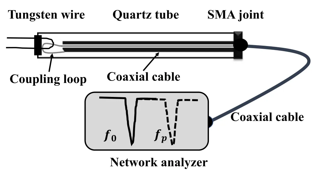
Figure 2.Schematic of the hairpin probe system.
A floating hairpin probe is held by a linear actuator so that it can be moved in the radial direction for the radially resolved measurement of the plasma density at the mid-gap between the electrodes.The hairpin probe diagnostic system consists of a floating hairpin probe, a coaxial cable, and a network analyzer,as shown in figure 2.The U-shape probe tip is made of a 0.2 mm diameter tungsten wire and has a length of 20 mm exposed to the plasma.It is kept electrically isolated via the coupling loop to minimize the RF disturbance.The other end of the probe equipped with a SubMiniature version A (SMA) connection is connected to the network analyzer via a coaxial cable.The measurement of the plasma density by the hairpin probe is theoretically based on the microwave resonance technique [42].When measuring the plasma density, the network analyzer is operated in the reflection mode,and its frequency scale can be adjusted in the range of 9 kHz–6 GHz.The plasma density is determined by the shift of resonant frequency in plasma with respect to that in the vacuum and can be expressed in the following equation
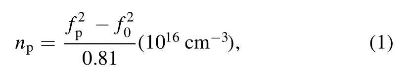
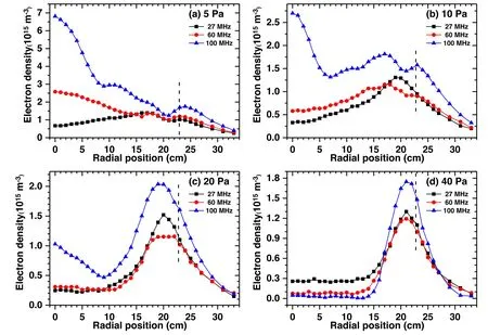
Figure 3.Radial distributions of the plasma density measured along the mid-gap between the electrodes for different driving frequencies of 27, 60, and 100 MHz at various pressures of (a) 5, (b) 10, (c) 20, and (d) 40 Pa with a fixed RF power of 80 W.
where,npis the plasma density,andf0andfpare the resonant frequencies of the hairpin probe in the vacuum and the plasma, respectively.Considering the presence of a sheath around the probe tips, we then numerically corrected the plasma density by using a sheath model [43].
3.Results and discussions
In this section, we present the measured results of the radial distributions of the plasma density measured along the midgap between two electrodes in pure argon capacitive discharges.The effects of the driving frequency and the RF power at different pressures were studied.After that, an LF power source (27 MHz) was introduced into the VHF discharge (100 MHz), aiming to get a better plasma uniformity.
3.1.Driving frequency effect at various pressures
The radial profiles of the plasma density along the reactor mid-gap at different driving frequencies (27, 60, and 100 MHz)at four selected pressures(5,10,20,and 40 Pa)are illustrated in figures 3(a)–(d), respectively.Please note thatrindicates the radial distance from the axis, and the vertical dashed lines indicate the location of the electrode edge.This applies to all figures in this paper.Due to the low plasma density,the skin effect is not important because the skin depth is larger than the electrode spacing.Taking the typical plasma density measured over the range of 1015–1016m?3as an example,the skin depth[38]is estimated to be in the range of 53.2–168.3 mm through equation(herecis the speed of light and ωpis the plasma frequency), which is much higher than the electrode spacing (30 mm).So, only the standing wave effect and the edge effect are considered in this work.
At 5 Pa(see figure 3(a))and 27 MHz,the plasma density generally increases,and then decreases upon increasing radial position fromr=0 cm tor≈33 cm, going through a minimum atr≈21 cm.No evidence shows the existence of the standing wave effect at this low frequency.As the driving frequency increases to 60 MHz, the plasma density increases within the region ofr≤15 cm, showing an obvious peak at the discharge center.This is attributed to the so-called standing wave effect,which leads to an enhanced electric field and, consequently, the maximum of the power deposition at the discharge center [6?11].Furthermore, the center-peak of the plasma density becomes much more significant because of the shortened EM wavelength when the driving frequency increases to 100 MHz.One can see that the location of the
first nominal standing wave nodes shifts fromr≈16 cm tor≈9 cm, when the driving frequency increases from 60 to 100 MHz.This approximately satisfies the relation that the EM wavelength is inversely proportional to its frequency.Note that at 100 MHz,there are two secondary density peaks around the positions ofr=9 cm andr≈17 cm, probably due to higher harmonics of the fundamental frequency caused by plasma series resonance[23].Besides,a density peak close to the outer edge was observed, which can be explained by the coupling effect between the electrode edge and the chamber sidewall.This effect is evident at relatively low pressures and high frequencies when discharge glow can be observed near the sidewall.
As the pressure increases, the standing wave effect that features a center-high density profile at higher driving frequencies,e.g.60 or 100 MHz,is gradually suppressed,while the edge effect that features an edge-high density profile at relatively low driving frequency, e.g.27.12 MHz, is enhanced.To be more specific, at 10 Pa, for example (see figure 3(b)), there is a degenerative center-peak at 100 MHz,and even no center-peak was observed at 60 MHz.At 20 Pa(see figure 3(c)),the center-peak of 100 MHz becomes lower,while a more prominent peak stands up at the inner edge of the electrode.While at 40 Pa the radial profiles of the plasma density at all frequencies, presented in figure 3(d), exhibit only one dominant peak at the inner edge of the electrode.A general explanation for the edge-peak of the density profile is an enhanced ionization there, due to the enhancement of the electric field as well as the power deposition there [19].It should be noted that the diffusion effect at high pressures is significantly limited because the electron energy relaxation length is much smaller than the discharge radius, so the plasma density is a local function of the power deposition.It is also noticed that the plasma density in the center region(r<14 cm) at 60 MHz and 100 MHz is close to zero.This phenomenon is known as the so-called ‘stop band’ effect[10, 11], which will be discussed in detail in section 3.2.
3.2.RF power effect at various pressures
Figure 4(a) shows the radial distributions of the plasma density measured at 100 MHz and 5 Pa for the RF power over a range from 30 to 200 W.To obtain a better visualization of all radial distributions, the experimental results in figure 4(a)are normalized and shown in figure 4(b) by dividing their respective maximum density.It can be seen from figure 4(a)that the radial profiles of the plasma density exhibit an overall increase at each radial position with increasing the RF power.Besides, each radial profile presents a multi-peak structure with a main peak at the discharge center and a secondary peak near the outer edge of the electrode.The center-peak in VHF CCP is obviously caused by the standing wave effect, while the near-edge peak is caused by the enhanced local edge electric field, which is attributed to the presence of the grounded shielding adjacent to the edge of the electrode as the description in section 2.
As the RF power is increased (see figure 4(b)), the main peak at the discharge center becomes more significant, and meanwhile, the first node shifts towards the electrode edge.As discussed in section 3.1, the skin effect is so faint that it can be neglected at such low plasma density,and the standing wave effect plays a dominant role in determining the radial profiles of the plasma density.Therefore, the standing wave effect is enhanced with increasing the RF power when the standing wavelength is increased.This suggests that our experimental result is consistent with the previous experimental observation, theoretical, and simulation results[6, 10, 11].We also noticed that at lower RF powers(30–100 W), the plasma density presents a multi-peak radial distribution.When the RF power is increased to 200 W, the center peak is so strong and broad that other secondary peaks are obscured.
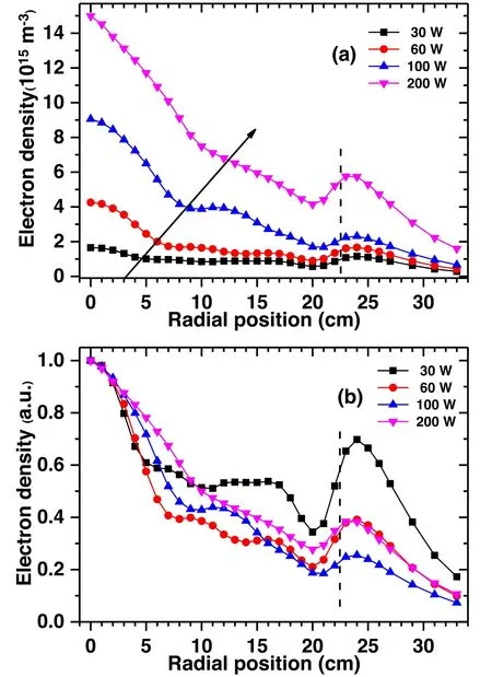
Figure 4.Radial distributions of the plasma density measured along the reactor mid-gap between the electrodes at 100 MHz and 5 Pa for different RF powers (30, 60, 100, and 200 W) (a) and normalized experimental results (b).Note that the arrow in figure 4(a) indicates the shift of the first node of the radial profile with the RF power.
At much higher pressures, i.e.40 Pa, only one evident peak at the inner edge of the powered electrode is observed and the plasma density at the discharge center tends to be zero when the RF power is below 200 W, as shown in figure 5.This phenomenon is caused by the combined effect of limited plasma radial diffusion at higher pressures and the so-called‘stop band’ effect, suggesting that the EM waves are highly damped as they are propagating from the powered electrode edge into the center.
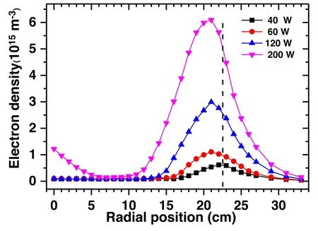
Figure 5.Radial distributions of the plasma density measured along the mid-gap between the electrodes at a driving frequency of 100 MHz and at a fixed pressure of 40 Pa for different powers.
In the RF power range of 40–120 W,the peak density falls in the range of 1×10¹⁵–3×10¹⁵m?3at the electrode inner edge,so the plasma frequency,wp/2π,is estimated to be in the range of 284–492 MHz,which is much larger than the driving frequency of 100 MHz.The series resonance frequency can be estimated by the equationwherelis the half-thickness of the bulk plasma,sis the sheath width,andlplusscan be assumed to be 15 mm(i.e.half the discharge spacing).If we assume the sheath thickness to be in the range of 0.1–0.6 mm,thewres/2π can be estimated to be in the range of 23–98 MHz, which is lower than 100 MHz.So, in this regime the driving frequency falls into the ‘stop band’, i.e.satisfying the relationwres≤w≤wp, where,wresandwpare series resonance frequency and plasma frequency,respectively.
As the RF power increases, the plasma peak density is raised,and the peak broadens.It is very interesting that when the RF power is raised to 200 W, a density peak emerges at the discharge center,suggesting that the standing wave effect comes into play again.At 200 W, the plasma frequencywp/2π is calculated to be about 701 MHz with an edge-peak density of 6.1×10¹⁵m?3, and the series resonance frequency is approximately to be in the range of 57–128 MHz,which is probably larger than the driving frequency, as a result, part of the EM wave propagates into the discharge center.This experimental observation is well consistent with previous simulation results [10].
3.3.Methods of improving the plasma uniformity
As described above, we have observed the evident standing wave effect and consequent severe plasma inhomogeneity,which shows an obvious peak at the discharge center when the discharge is driven by a VHF,especially at relatively low pressures.In this section, a LF power source (27 MHz) is introduced to the VHF (100 MHz) discharge to improve the plasma uniformity.Figure 6 shows the measured radial distributions of plasma density as a function of the LF power operated at several lower pressures (2.5, 5, and 10 Pa).The LF power ranges from 0 to 150 W, and the VHF power is fixed at 60 W.We can see that the radial plasma density exhibits an overall increase and the plasma uniformity varies significantly when increasing the LF power.
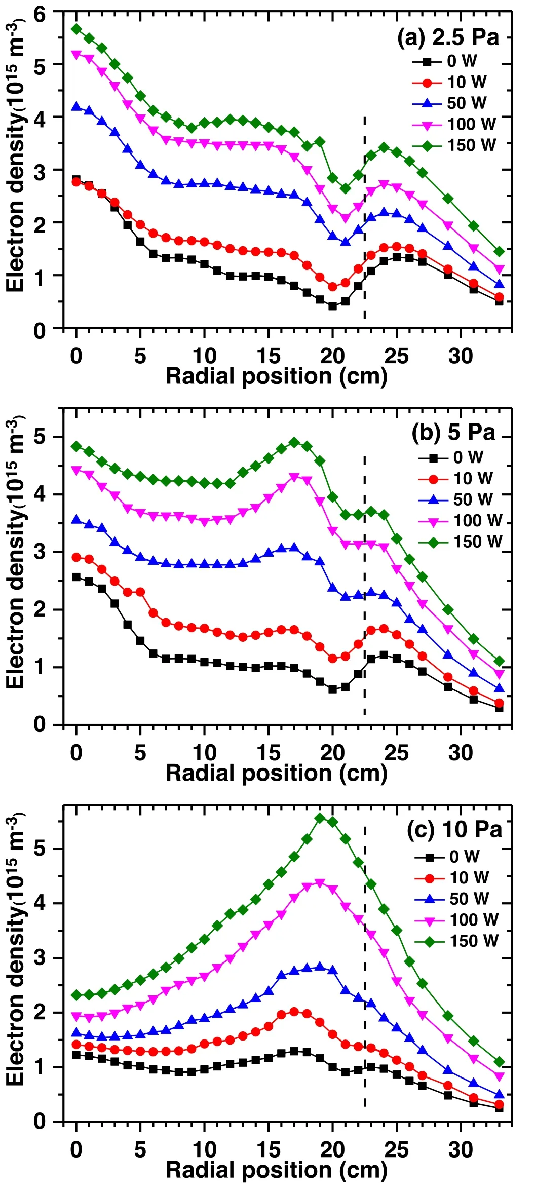
Figure 6.Radial distributions of the plasma density measured along the reactor mid-gap between the electrodes as a function of the LF power(27 MHz)for three pressure values of(a)2.5,(b)5,and(c)10 Pa.The plasma is driven by the combinations of 27 and 100 MHz,and the 100 MHz power is fixed at 60 W.
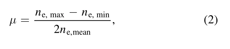

Figure 7.The plasma non-uniformity factors μ with the variation of the LF power (27 MHz) at different pressures.Experimental conditions are the same as in figure 6.
To better describe the degree of the plasma uniformity,a plasma non-uniformity factor μ is defined as the following expression [36, 44]wherene,max,ne,minandne,meanrespectively represent the maximum, minimum, and mean values of the plasma density in the region from the reactor center (r=0 cm) to the radial position(r=18 cm).The region is selected a bit smaller than the electrode radius because the plasma density at the radial edge is influenced by the geometry of the electrode.From the equation(2),we can clearly know that the smaller its value is,the better plasma uniformity is.
The variation of corresponding plasma non-uniformity factors μ of the measured results in figure 6 is shown in figure 7.Besides,the plasma densities as a function of the LF power at two typical radial positions,r=0 cm andr=17 cm, respectively, are shown in figures 8(a)–(c) for a better visualization of the radial profiles.It can be seen from figures 7 and 8 that the plasma uniformity changes significantly with the addition of the LF power.
At the low pressure of 2.5 Pa (figure 6(a)) when the LF power equals to zero, the plasma density shows a typical multi-peak radial distribution with an obvious peak at the discharge center.From figure 7 we can know that the nonuniformity factor μ is higher than 0.73, suggesting a very poor plasma uniformity.When the LF power is increased to 10 W,and the plasma non-uniformity factor is 0.44,implying that the plasma uniformity is improved.However, μ changes slightly by further increasing the LF power to 150 W.This is because at such a low pressure, the enhanced radial diffusion effect is important [19] and comparable to that of the edge effect (contributes to an edge-high radial distribution) when increasing the LF power.Just as shown in figure 8(a),the density difference between the two typical positions(r=0 cm andr=17 cm) remains unchanged when increasing the LF power from 10 to 150 W.In other words,the edge effect at 27 MHz is not evident compared with the combination of its radial diffusion effect and the standing wave effect at 100 MHz at such a low pressure.Therefore,the improvement of plasma uniformity is limited at 2.5 Pa.
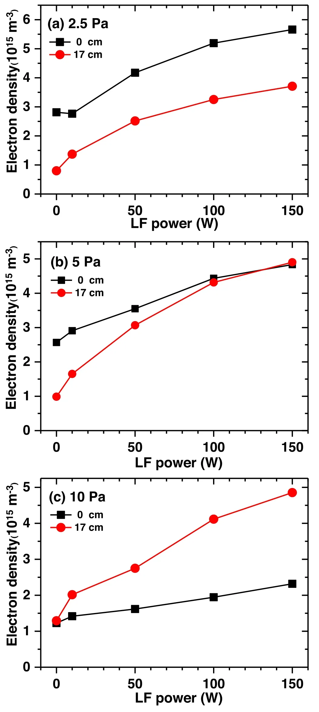
Figure 8.The plasma density at the radial positions of r=0 cm and r=17 cm as a function of the LF power (27 MHz) at different pressures of (a) 2.5, (b) 5, and (c) 10 Pa.The experimental conditions are the same as in figure 6.
At a relatively high pressure of 10 Pa (see figure 6(c)),two peaks with comparable density can be found at the discharge center (r=0 cm) and the inner edge (aroundr=17 cm) when the LF power is zero.The density ration(r=0 cm)/n(r=17 cm)is close to 1(see figure 8(c)),and the plasma density shows a relatively uniform distribution with a lower μ of 0.18(see figure 7).However,with increase of the LF power, the inner edge peak becomes more obvious and the center-peak gradually diminishes.The center-peak density becomes only about half the edge-peak density when the LF power is increased to 100 and 150 W(see figure 8(c)),indicating a rather worse plasma uniformity,corresponding to an increase of the plasma non-uniformity factor μ to 0.42.This is because the edge effect at 10 Pa is much stronger than that of 2.5 Pa,while its radial diffusion effect is much weaker.So, increasing the LF power at 10 Pa will cause more local power deposition at the edge of the powered electrode and,consequently, a higher plasma density there, resulting in a more severe plasma inhomogeneity.
At the intermediate pressure of 5 Pa (see figure 6(b))when the LF power is zero,the plasma density shows a multipeak radial distribution with an obvious peak at the discharge center, which resembles the case at 2.5 Pa.As the LF power increases,the plasma density has an overall increase while the edge-peak density (aroundr=17 cm) exhibits a more significant increase than that at the discharge center.When the LF power is increased to 100 or 150 W, the peak density at the edge (aroundr=17 cm) becomes comparable to the center-peak density (r=0 cm), as shown in figure 8(b).In this regime, the center-peak density caused mainly by the standing wave effect (VHF, 100 MHz) is well compensated by the edge effect which is dominated at relatively low driving frequency i.e.27 MHz,leading to great improvement of the plasma radial uniformity.As shown in figure 7, the plasma non-uniformity factor μ at 5 Pa is 0.57,0.13,and 0.08 when the LF power equals to 0 W, 50 W, and 150 W,respectively.Here, μ=0.08 means a much better plasma uniformity.In addition, we mentioned that when the plasma uniformity is optimal at a LF power of 150 W(μ=0.08),the plasma presents a‘basin-like’distribution rather than an ideal flat distribution.This can be attributed to the fact that the electrode radius is so large that the radial region between the center- and edge-peak (i.e.the position ofr=8 cm) get limited effect from the standing wave effect and the edge effect,causing a concave there.It can be inferred that we can get a much better plasma uniformity with a flat radial plasma density distribution if the electrode’s radius was smaller.
Overall, we observe the distinct variations of the plasma uniformity when introducing the LF source into a VHF discharge by balancing the standing wave effect with the edge effect.However, the effect of this method depends strongly on the discharge pressure, the magnitude of the LF power,and even the electrode’s size.We can get a much better plasma uniformity if we choose an appropriate LF power, a gas pressure and other appropriate discharge parameters.
4.Conclusion
In conclusion, we have measured the radial profiles of the plasma density in a large-area (450 mm in electrode diameter), VHF capacitive discharge by using a floating hairpin probe.In a low-pressure and VHF discharge, the standing wave effect can profoundly affect the plasma radial profiles,and an evident peak can be observed in the electrode center.There are also several secondary gentle peaks between the discharge center and the electrode edge that may be caused by higher harmonics of the driving frequency excited by the plasma series resonance effect.When the pressure is increased to 40 Pa, the standing wave is suppressed because the EM waves are highly damped as they are propagating from the electrode edge into the discharge center,which is the so-called ‘stop band’ phenomenon.Based on the experimental results, the plasma density radial profile is strongly affected by the standing wave effect and serious plasma nonuniformity can be found especially at a relatively high frequency and low pressure.In addition, it is found that in a discharge driven by an LF of 27 MHz, the edge effect dominates the radial profile of the plasma density, which always peaks near the electrode edge at various pressures.Therefore, to get a better plasma uniformity, the LF power source of 27 MHz is introduced to the VHF (100 MHz)discharge by compromising the edge effect with the standing wave effect.As was expected,the plasma uniformity changes significantly when adjusting the LF power and a much better plasma radial uniformity can be obtained by choosing an appropriate LF power and a gas pressure.In future work, to analyze the physical mechanisms of the multi-peak and complex radial distribution of the plasma density,we will try to use a B-dot probe to measure the radial distributions of the harmonic magnetic field.Based on the measurements, some methods would be adopted to get a much better plasma uniformity.
Acknowledgments
This work was funded by National Natural Science Foundation of China(Nos.11875100,11935005 and 11722541).The author Daoman Han also appreciates the financial support from the China Scholarship Council.
ORCID iDs
猜你喜歡
應(yīng)用數(shù)學(xué)(2022年3期)2022-07-07 07:36:14
Plasma Science and Technology(2022年5期)2022-06-01 07:55:50
Plasma Science and Technology(2022年4期)2022-05-05 01:48:36
Plasma Science and Technology(2022年2期)2022-03-10 03:49:40
Plasma Science and Technology(2021年11期)2021-11-30 08:28:40
Chinese Physics B(2021年4期)2021-05-06 08:55:10
Chinese Physics B(2021年3期)2021-03-19 03:20:52
應(yīng)用數(shù)學(xué)(2020年3期)2020-07-28 01:13:40
作文評點(diǎn)報(bào)·低幼版(2019年36期)2019-10-20 13:58:15
小學(xué)生優(yōu)秀作文(低年級)(2019年3期)2019-04-09 11:56:04
 Plasma Science and Technology2021年5期
- Plasma Science and Technology的其它文章
- UV and soft x-ray emission from gaseous and solid targets employing SiC detectors
- The acceleration mechanism of shock wave induced by millisecond-nanosecond combined-pulse laser on silicon
- Investigation of non-thermal atmospheric plasma for the degradation of avermectin solution
- Laser-induced breakdown spectroscopy for the classification of wood materials using machine learning methods combined with feature selection
- Colorimetric quantification of aqueous hydrogen peroxide in the DC plasma-liquid system
- Plasma-assisted Co/Zr-metal organic framework catalysis of CO2 hydrogenation:influence of Co precursors