
Simulation study on the influence of magnetic field in the near-anode region on anode power deposition of ATON-type Hall thruster
2020-09-14 01:13:38HongboSU蘇宏博HongLI李鴻YongjieDING丁永杰LiqiuWEI魏立秋XuZHANG張旭ChaoyingZHOU周超英andDarenYU于達(dá)仁
Plasma Science and Technology 2020年9期
Hongbo SU (蘇宏博),Hong LI (李鴻),2,5,Yongjie DING (丁永杰),2,5,Liqiu WEI (魏立秋),2,Xu ZHANG (張旭),Chaoying ZHOU (周超英) and Daren YU (于達(dá)仁),2
1 Lab of Plasma Propulsion,Harbin Institute of Technology (HIT),Harbin 150001,People’s Republic of China
2 Lab of Electric Drive &Propulsion Technology,Harbin Institute of Technology (HIT),Harbin 150001,People’s Republic of China
3 Institute of Telecommunication Satellite,China Academy of Space Technology,Beijing 100094,People’s Republic of China
4 School of Mechanical and Electrical Automation,Harbin Institute of Technology (HIT),Shenzhen 518055,People’s Republic of China
5 Authors to whom any correspondence should be addressed.
Abstract
Keywords:Hall thruster,magnetic field,near-anode,power deposition
1.Introduction
At present,the Hall thruster is the most widely used electric propulsion system in attitude control,station keeping,and orbit transfer due to the simple structure,moderate specific impulse,and high efficiency[1,2].The current development direction is towards a Hall thruster with high efficiency,high reliability,high stability [3]and long life [4].As in many types of Hall thrusters,the ATON-type Hall thruster has the characteristics of a large magnetic field gradient in the channel and a large curvature of magnetic field line,which can realize high ionization.However,in order to form the magnetic field with this characteristic,an additional coil is placed inside the ATON-type thruster,which will also lead to the obvious intersection of the magnetic field line and the anode end face,which is equivalent to providing a shortcut for nearby electrons.Some studies have pointed out that the peak of the ATON-type thruster is always the highest power deposition and the highest temperature (higher than 600 °C) [5].In the literature[5],it is pointed out that the peak temperature of the anode ring is always at the intersection of the tip and the anode ring,no matter how large the magnetic field intensity or gradient is.This shows that when there are electrons gathering at the intersection,the distribution of thermal load will be uneven,which may potentially damage the reliability.The problem of anode power deposition is mainly reflected in the very concentrated anode temperature distribution and the high overall anode temperature [6,7],which may potentially damage the reliability of the Hall thruster.
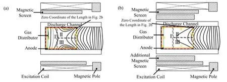
Figure 1.Magnetic field topology of thruster.(a) Original magnetic field,and (b) magnetic field with additional magnetic screen.
In order to alleviate the problem of the anode power deposition of the ATON-type Hall thruster,we can refer to the existing research on anode power deposition.Mazouffre [8]reduced the electron current and the interaction between plasma and channel by increasing the channel width and then reducing the surface-to-volume ratio (however,the large electron current to anode might sometimes be useful to increase the thrust and thrust-to-power ratio in metallic plasma-propellant low power vacuum arc thrusters [9]),and Dorf [10]proposed the method of reducing the anode thermal power by anode coating.In order to alleviate the problem of anode overheating caused by anode power deposition,Pote [11]increased the anode area by changing the anode topology,or by cooling the anode[12],etc.In summary,a lot of research has been done to solve the power deposition problem in the near-anode region.It can be seen that this problem is important for the discharge stability and life of the Hall thruster.At the same time,we also see the problems of the above solutions:increasing the channel width will reduce the flow density and ionization under the condition of constant flow,change the anode topology and surface characteristics,and coating or cooling the anode will increase the complexity of the thruster and affect the discharge stability,which are not conducive to the discharge of the Hall thruster.Therefore,we need a new idea to study the anode power deposition of the ATON-type Hall thruster.
Therefore,we provide a magnetic field design to reduce anode power deposition.Magnetic field is an effective means to control the motion of electrons.Whether inside or outside the thruster channel,the change of magnetic field will affect the distribution of plasma parameters [13,14].In particular,the electrons in the near-anode region are mostly low-energy electrons [15],which are easy to magnetize by the magnetic field.Thus,we change the characteristics of the magnetic field upstream of the thruster channel by setting an additional magnetic screen,and study the influence of changing the magnetic field on the plasma parameters and anode power deposition of the Hall thruster by particle-in-cell (PIC) simulation.
This paper is divided into the following five parts:the second section is the thruster and magnetic field characteristics,the third section is the description of the PIC model and boundary conditions,the fourth section is simulation results,the fifth section is analysis and discussion,the last section is conclusion.
2.Thruster and magnetic field characteristics
This research is based on the model of the 1 kW SPT-ATON Hall thruster.It is developed from the SPT series.Compared with the traditional SPT magnetic field [16],it has more symmetrical magnetic field characteristics,increased magnetic field gradient,and has zero magnetic point and negative magnetic field gradient region.Its typical magnetic field topology [17]is shown in figure 1(a),which is called the original magnetic field.This focusing magnetic field structure is formed by the internal and external excitation coils.The maximum intensity of the magnetic field is pushed to the channel exit,making the magnetic field at the channel exit 99% of the maximum magnetic field (figure 2).Meanwhile,the U-shaped anode structure is adopted.There is a certain distance between the two sides of the U-shaped anode and the ceramic wall.It is worth noting that in the near-anode region of the original thruster,although the magnetic field strength is not high,there are many magnetic lines intersecting with the U-shaped anode wall.On this basis,we use the additional magnetic screen to change the magnetic field topology of the near-anode region.As shown in figure 1(b),under the effect of the additional magnetic screen,most of the magnetic field lines in the near-anode region are short circuited.At the same time,it can be seen that the design of the additional magnetic screen has little influence on the overall magnetic field topology in the channel.As shown in figure 2,the maximum magnetic field intensity and position,magnetic field gradient and extrapolation degree in the channel have no significant difference.Therefore,it can be said that the effect of the additional magnetic screen in fact mainly changes the characteristic of magnetic field in the near-anode region.
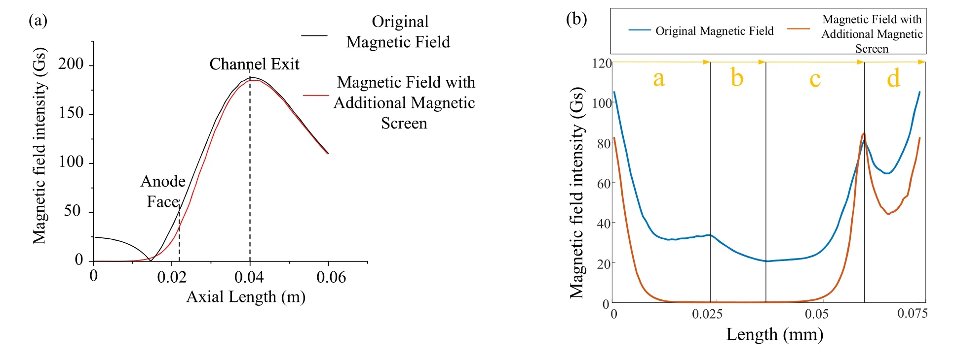
Figure 2.(a) Distribution of magnetic field intensity at the middle diameter position in the channel.(b) Magnetic field at characteristic position in channel.
For the convenience of expression,the near-anode region in the channel is divided in three regions(I,II,III);region I is near the anode bottom,region II is near the outer wall,and region III is near the inner wall.Combined with figures 1,2(a),and (b),the characteristics of the three regions are as follows:there are a large number of radial magnetic fluxes in region I of the original magnetic field,and the magnetic field can reach 25 Gs,while the magnetic field strength is less than 5 Gs in region I of the magnetic field with the additional magnetic screen,because magnetic fluxes are short circuited by the soft magnetic material.In regions II,III of the original magnetic field,there are many magnetic lines intersecting with the U-shaped anode,while in the magnetic field of the additional magnetic screen,there are almost no magnetic lines intersecting with the anode due to the short circuit of the magnetic lines.Figure 2(b) shows the difference in magnetic field strength and gradient in the same position,which is shown in figures 1 and 2(a).
After defining the two kinds of magnetic field characteristics,PIC simulation is used to simulate the plasma characteristics in the two cases.The influence of the two kinds of magnetic field characteristics on the anode deposition of the Hall thruster is studied by analyzing the distribution of plasma parameters in the near-anode region.
3.Description of the PIC model and boundary conditions
For analyzing the behavior of the plasma in the Hall thruster,the typical method is particle-in-cell Monte Carlo collisional(PIC-MCC)simulation,which combines the PIC method with the Monte Carlo method.A 2D-3V PIC-MCC model has been developed by Harbin Institute of Technology for characterizing the electron transport and wall sheath of Hall thrusters[18-23].The densities of ions and electrons could be described by simulating their trajectories.The initial velocity of new particles is treated by half-Maxwell distribution and the electric field is obtained by solving the Poisson equation by the dynamic alternating direction implicit(DADI)method.The ‘dynamic’ ADI method was developed by Said Doss[24],involving a computerized strategy for completely automatic change of the iteration parameter Δt in ADI methods for linear or nonlinear elliptic equations.The collisions between electrons and neutral atoms are simulated by the Monte Carlo method[25].Because of the difference in the magnetic field between the discharge channel and the plume area,the Bohm collision frequency is defined asνB=κBωB/16,whereωBis the electron cyclotron frequency,the coefficientκBis adjustable (set as 1/16 and 1/4 of the upstream and downstream area of the discharge channel).At the same time,in order to ensure the convergence of the simulation,the quasi neutral injection method is used to govern the electron injection channel.
In order to speed up the calculation,the number of grids and iterations can be reduced by increasing the permittivity of vacuum by γ2times.This accelerated calculation method is proposed for the first time by Szabo in 2001 [26].According to his research,the calculation accuracy can satisfy the requirements when γ2is set to 400,and it is shown that the smaller the γ2value is,the more consistent with the reality it is.Because with the amplification of the vacuum permittivity,the Debye length is inevitably increased,the sheath thickness is increased,and the charge imbalance area is artificially increased.Thus,in order to maintain the discharge characteristics,γ2should not be too large.Based on these works,we select a more stringent condition through experiments.Therefore,γ2is set as 144 to speed up the calculation without large deviations.In fact,since the sheath thickness is usually about 10?1mm and the channel width is a few centimeters,choosing γ2as 144 will only increase the sheath thickness to about 1 mm,which is still much smaller than the channel width,so it has little impact on the discharge.
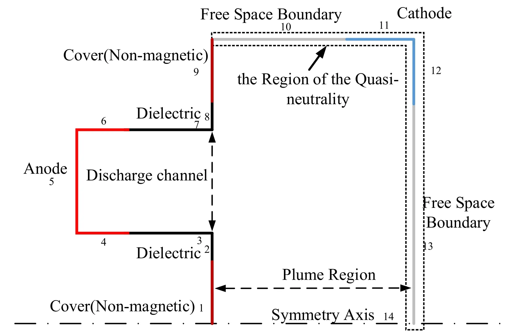
Figure 3.Schematic of the numerical simulation model.
In addition,to reduce the simulation time,the mass of the heavy particles such as ions and atoms is reduced by a factor of f to enable the particles to move faster.Accordingly,the mass of heavy particles is multiplied by 1/f,the time scale is decreased bywith the increase of ion velocity,and the collision cross section has to be increased by,preserving the plasma density in the discharge channel.Although f can affect the ratio of collision free path and channel size,the simulation result shows that the influence of this change on plasma distribution is little.Thus,according to the requirements of the Hall parameter in a Hall thruster,we setto 25[26].Some assumptions are made in the model,including a constant velocity of neutral gas,a quasi-neutral boundary of cathode,and the half-Maxwellian distribution of the initial particle.Furthermore,the collisions between atoms and atoms,and atoms and ions,are ignored.Besides,the conservation of wall energy,anomalous transport (Bohm diffusion) and wall sheaths are considered in the model.This PIC model has been used to investigate the plasma parameter distribution and anode power deposition in the near anode region of the Hall thruster.
The boundaries of the numerical simulation model are shown in figure 3.The nonmagnetic cover(the numbers are 1,9),dielectric (2,3,7,8),anode (4,5,6),cathode (11,12),free-space boundary(10,13)and symmetry boundary(14)are shown respectively.The secondary electron emission model on all ceramic walls is considered,and the cathode potential was set to 0 V,the PIC calculation was performed for a discharge voltage of 300 V and a propellant mass flow of 3.9 mg s?1.
4.Results of numerical simulation
First of all,the difference between electron conduction characteristics in the near-anode region before and after changing the magnetic field is shown in figures 4 and 5,we can see the distribution of electron current in the near-anode region along the axial and radial directions,respectively.Figure 6 shows the difference in the energy distribution of electrons.
4.1.The distribution of axial electron current density
In figure 4(a),the distribution of the axial electron current density is uneven in regions II and III of the original magnetic field,and the axial electron current density is more concentrated in the area where the magnetic field line intersects intensively with the U-shaped anode in the upstream (it is specified that the anode is upstream and the electron current is negative when the electron moves towards the anode).Moreover,due to the joint influence of the anode and the magnetic field line,the direction of the axial electron current density is along the exit of the channel(-2000 A m?2),while in the downstream regions II and III,the axial electron current density is in the range of 2000-4000 A m?2,and in region I,the axial electron current density is 2000 A m?2.However,the distribution of axial electron current density in figure 4(b)is obviously different.The overall distribution of electron current density in regions II and III is more uniform,at the same time,the electron current density in region I is higher.For the positive electron current generated near the anode end face,it is the result of the movement of low-energy electrons(see the electron energy distribution in figure 6) along the magnetic field line in the process of moving towards the anode wall.Because the magnetic field in this area is stronger and the magnetic field line has a positive component,under the action of high potential of the anode,a positive electron current is generated.
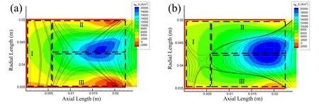
Figure 4.The distribution of axial electron current density in the channel(red line is the anode)near the anode region.(a)Original magnetic field,(b) magnetic field with the additional magnetic screen.
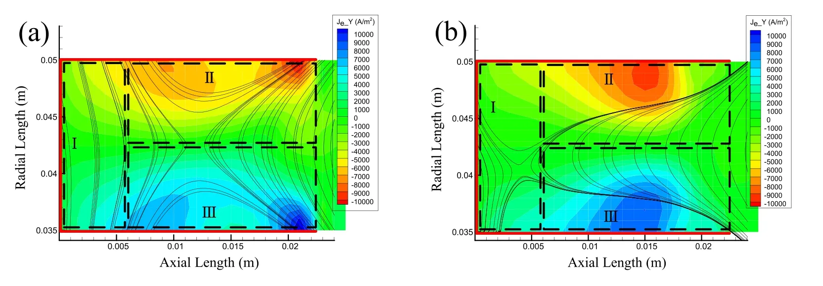
Figure 5.The distribution of radial electron current density in the channel(red line is anode)near anode region.(a)Original magnetic field,(b) magnetic field with the additional magnetic screen.
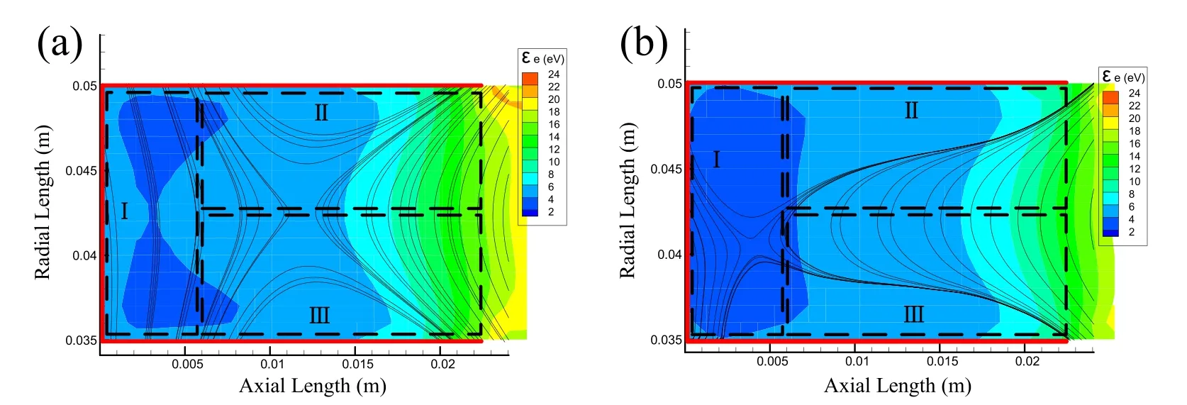
Figure 6.The distribution of electron energy in the channel (red line is anode).(a) Original magnetic field,(b) magnetic field with the additional magnetic screen.
4.2.The distribution of radial electron current density
We should not only pay attention to the axial direction,but also combine the radial direction to analyze the electron conduction characteristics.Therefore,the radial electron current density is selected.As shown in figure 5(a),the radial electron current density is very uneven on the inner and outer walls of the U-shaped anode.Take region III near the inner wall of the anode as an example;the radial electron current density can reach from?7000 to?10 000 A m?2at the intersection position of the magnetic line and the anode,while it can reach from?2000 to?3000 A m?2at the position with sparse magnetic lines.The radial electron current density is relatively more even after the additional magnetic screen is adopted.It can be seen in region III of figure 5(b) that the radial electron current density on the inner anode wall changes in the range from?5000 to?8000 A m?2,which is not only more evenly distributed,but also has lower peak value.
4.3.The distribution of electron energy
The difference in electron energy distribution is shown in figure 6.In region I,especially near the anode bottom (axial length=0 m),the electron energy of the magnetic field with the additional magnetic screen is about 2 eV,which is lower than that of the original magnetic field.In regions II and III,compared with the original magnetic field,the gradient of electron energy of the magnetic field with the additional magnetic screen compresses towards the downstream of the channel,and the area of the low-energy electron energy near the anode is lengthened,which results in the electron energy near the surface of the U-shaped anode being generally low,and the electron energy range changes from 8-24 eV to 8-18 eV,especially near the end face of the anode(x=0.0225 m).
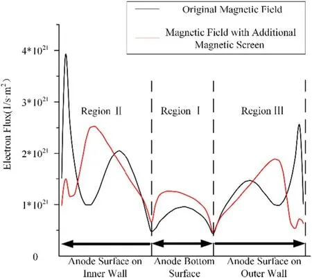
Figure 7.Comparison of electron incident flux on anode.
4.4.Anode power deposition
After passing through the near-anode region,the electrons are finally deposited on the anode surface.Therefore,the electron power deposition on the anode surface should be analyzed after the distribution of electron parameters near the anode in the channel is known.
Obviously,the characteristics of electron power deposition on the anode will inherit its characteristics in the nearanode region.Thus,the electron flux deposition distribution in figure 7 is similar to the electron current density distribution in the channel in figures 4 and 5.The electron flux under the original magnetic field is larger at both ends of regions II and III,but lower in the middle.At the same time,because of the dense radial magnetic lines,the electron flux under the original magnetic field is lower in region I.The mean energy of electrons deposited on the walls is shown in figure 8,and this distribution is similar to electron energy distribution in the channel in figure 6.The electron energy under the original magnetic field is more concentrated on the end face of the anode in regions II and III,and the overall energy is higher;while in region I,it is completely higher than that under the magnetic field with the additional magnetic screen.At the same time,in order to make it easier for readers to understand the difference of electronic parameters along the anode,we also calculated the energy flux distribution along the anode.As shown in figure 9,it can be seen that at the cusp point of the anode end face,the energy flux of the original thruster is significantly higher than that of the thruster with the additional magnetic screen.
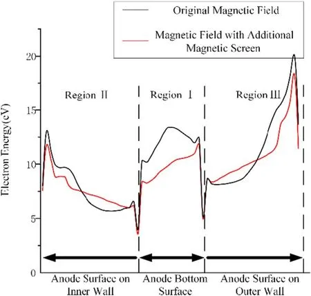
Figure 8.Comparison of electron energy on anode.
Figure 9.Comparison of electron energy flux on anode.
The electron power deposition on the anode can be defined as the sum of the number and energy of electrons incident on the anode surface in a certain time step.Thus,table 1 shows the electron power deposition on the anode under the two magnetic fields.It can be seen that due to the addition of the additional magnetic screen,the electron power deposition on the anode decreased from the original 45 W to 36 W,reducing by 20%.At the same time,the power deposition of plasma on the wall is also calculated,the difference between the two is less than 3%,which shows that the power deposition of ceramics has no obvious effect on the anode.We also compared the discharge performance of the thruster.As shown in table 2,we can see that compared with the thruster with original magnetic field,the discharge performance of the thruster with the additional magnetic screen is slightly reduced,but the difference is about 2%.Based on the above comparison,we believe that the additional magnetic screen does not significantly change the discharge performance of the thruster.
Figure 10.Electron motion behavior.(a) Original magnetic field,(b) magnetic field with the additional magnetic screen.

Table 1.Comparison of electron power deposition on anode and plasma power deposition on wall.
Table 2.Comparison of discharge performance.
5.Analysis and discussion
From the analysis of the numerical simulation results,it can be seen that the area where the electron parameters change most in the near-anode region coincides with the area where the magnetic lines change intensively.It can be seen from the typical parameters of the plasma in the near-anode region that the electrons in this region are usually low-energy electrons(no more than 10 eV).In region I,the electrons will deposit to both sides of the anode bottom due to the existence of the magnetic field line,but because the magnetic field here is only 20 Gs and the Larmor radius of the electrons is in the order of millimeters,the effect of the magnetic field line driving the electron motion is not obvious.Compared with the weak magnetic field in region I,the magnetic field in regions II and III is stronger,so the electrons in zone 2 and zone 3 are easily affected by the magnetic field,and the resistance along the B direction is the smallest,so the low-energy electrons will have the motion component along the B direction.As shown in figure 10(a),in regions II and III,when a large number of magnetic lines intersect with the U-shaped anode,the lowenergy electrons will easily arrive at the anode along the magnetic line,resulting in a high concentration of electrons at this location.Meanwhile,figure 10(b) shows relatively less concentration of electrons due to the absence of a large number of magnetic lines.This also explains the difference between the axial and radial electron currents in figures 3 and 4.In the original thruster,there are a large number of magnetic lines intersecting with the anode end face,which makes it easy for electrons to be guided to the anode top by these magnetic lines.In this process,the energy consumption of electrons is less,as shown in figures 7 and 8.However,for thrusters with an additional magnetic screen,the magnetic field strength in the near anode area is smaller,so the electron flux is not concentrated on the anode end face,but rather more evenly into the anode,and electrons in this process tend to consume more energy.Therefore,the variation results in a 20% difference in the deposition of electronic power on the anode.
The dispersion of electron current density and low electron energy near the anode can reduce the electron power deposition into the anode,thus reducing the problem of high and over-concentration temperature of the anode.Some studies[5]have shown that the intersection of the magnetic field cusp and anode is highly coincident with the anode temperature peak position,which will lead to uneven temperature distribution on the anode,leading to a local overheating phenomenon,thus restricting the life of the Hall thruster.Therefore,this study aims to alleviate this problem by changing the magnetic field characteristics in the near-anode region.
6.Conclusion
The ATON-type Hall thruster has the characteristics of a large magnetic field gradient in the channel and a large curvature of magnetic field line,which can realize high ionization.However,in order to form the magnetic field with this characteristic,an additional coil is placed inside the ATON-type thruster,which will also lead to the obvious intersection of the magnetic field line and the anode end face,which is equivalent to providing a shortcut for nearby electrons.The highest deposition of power and temperature is always near the cusp.This shows that when there are electrons gathering at the cusp,the distribution of heat load will be uniform,which will potentially damage the reliability.Therefore,we optimize the magnetic field near the anode.In this paper,the PIC simulation method is used to study the influence of the magnetic field in the near-anode region on the power deposition of the anode.Through the analysis of the simulation results,it can be seen that the low-energy electrons are easy to magnetize and the sharp point phenomenon formed by the intersection of a large number of magnetic lines and the anode in the traditional magnetic field makes it easy for the low-energy electrons to concentrate on the end face of the U-shaped anode,and it is difficult to reach the side and bottom surfaces of the anode evenly,so that the uneven distribution of anode power deposition leads to local overheating.However,the additional magnetic screen can short circuit the magnetic lines near the anode,which makes the low-energy electrons deposit more evenly on both sides of the anode wall,and may increase the electron collision to further dissipate energy before reaching the anode bottom.The simulation results show that the magnetic field formed by the additional magnetic screen can alleviate the phenomenon of the over-concentration of power deposition on the anode and reduce the power deposition by 20% on the premise of ensuring the overall magnetic field characteristics of the ATON-type thruster.
Acknowledgments
The authors gratefully acknowledge the financial support from National Natural Science Foundation of China(Nos.51777045,51736003) and supply of the Hunan Science and Technology Innovation Project (No.2019RS1102) and supply of the Shenzhen Technology Projects (No.JCYJ20170307151117299)
猜你喜歡
Journal of Donghua University(English Edition)(2023年5期)2023-10-29 11:41:42
金秋(2023年8期)2023-09-14 01:10:42
金秋(2020年6期)2020-08-17 01:08:38
——機(jī)械廠)
中國釀造(2019年9期)2019-10-08 05:44:04
金秋(2019年4期)2019-05-22 12:38:22
Communications in Theoretical Physics(2018年7期)2018-07-09 06:46:36
作文評(píng)點(diǎn)報(bào)·低幼版(2017年42期)2017-11-16 19:45:26
小天使·一年級(jí)語數(shù)英綜合(2017年4期)2017-04-18 18:08:14
初中生學(xué)習(xí)·高(2016年11期)2016-12-20 19:48:54
中學(xué)生數(shù)理化·高二版(2016年8期)2016-05-14 13:19:34
 Plasma Science and Technology2020年9期
- Plasma Science and Technology的其它文章
- Special issue on selected papers from CEPC 2019
- Life test research of a high specific impulse Hall thruster HEP-140MF
- Magnet stage optimization of 5 kW multicusped field thruster
- Application and development of the pulsed plasma thruster
- Numerical simulation of the plasma acceleration process in a magnetically enhanced micro-cathode vacuum arc thruster
- Discharge instability in a plasma contactor