
Application and development of the pulsed plasma thruster
2020-09-14 01:13:42
Plasma Science and Technology 2020年9期
School of Aerospace Engineering,Beijing Institute of Technology,Beijing 100081,People’s Republic of China
Abstract
Keywords:pulsed plasma thruster,performance,modeling,design,propellant material
1.Introduction
Electric propulsion is focused on by spacecraft designers to save propellant mass because its specific impulse(the impulse produced by a unit mass of propellant in a thruster) is one order of magnitude higher than that of chemical propulsion[1].The pulsed plasma thruster (PPT) is the first electric propulsion system successfully applied to spacecraft primarily because its system is simple[2].However,the efficiency and specific impulse of the PPT are lower than those of Hall thrusters and ion thrusters,even though its specific impulse is also much greater than those of cold gas thrusters and chemical thrusters.Therefore,the applications of PPTs are more limited than Hall thrusters and ion thrusters at present because high efficiency and high specific impulse are more important to geosynchronous orbit (GEO) satellites and deep space missions [1].However,the PPT is a much simpler device which can be designed,constructed easily and operated at very low power.Therefore,PPTs are suitable for small satellite propulsion missions.
Small satellites have been growing rapidly in recent years[3].In 2019,SpaceWorks Commercial forecasted that more than 2000 small satellites under 50 kg (nano/microsatellite)will be launched in the next five years [4].Due to the restrictions of cost,power,volume and mass,most small satellites under 50 kg did not use propulsion systems [2].Nevertheless,as new applications and requirements for small satellites emerge,the demand for propulsion systems will increase.Micropropulsion systems can increase the orbit control ability and lifetime of small satellites under 50 kg,but must satisfy the small volume,light weight,low power,enough total impulse (the impulse produced by the total propellant of a thruster)and low cost requirements[4].As the small satellite market grows,PPTs are attracting attention again because it is difficult for many electric propulsion systems(including Hall and ion thrusters)to satisfy the small volume,light weight,low power and low cost requirements [4].
PPTs are very competitive in the micropropulsion field for the following reasons.
(1) Low power-The value of the electrical power of a small satellite usually depends on the satellite size and ranges from 5 W on a 1 U (a cube of 10 cm×10 cm×10 cm volume) CubeSat to several hundred watts on a 50 kg satellite [4].Less power can be provided to a propulsion system.At this electrical power level,many electric thrusters,including traditional ion and Hall thrusters,cannot work.A PPT can provide a specific impulse above 500 s under 2 W [5],which is 2-10 times higher than that of cold gas and chemical propulsion.
(2) Light weight and small volume-A PPT system is very simple.The volume and weight of a PPT system,including the power processing unit (PPU) and control unit,are usually less than 0.5 U and 0.5 kg,respectively.
(3) High safety and reliability-A PPT usually uses solid propellant (usually Teflon) that features a long storage life and wide operation temperature range,is nontoxic,has no mechanical valves and has no pressure vessel.A PPT system is usually simple,and its only moving part is the spring for feeding the propellant.
(4) Variable thrust and a precise impulse bit (the impulse produced by every pulsed thruster operation)-The thrust of a PPT can be controlled by controlling the operation frequency.The μN(yùn)s magnitude impulse bit is suitable for precise orbit and attitude control missions [2].
(5) Low cost-Most small satellite designers are either academic institutes or small organizations which have small budgets [1].The low cost of small satellites restricts the total cost of a micropropulsion system.Therefore,a simple design is very important for micropropulsion systems.
The low thrust efficiency (fraction of the initial capacitor energy that is converted into directed kinetic energy of the exhaust) is the largest disadvantage of PPTs.Nevertheless,the problem is not important for spacecraft attitude control and small satellite propulsion missions,which focus more on reliability,system simplicity,low cost and the ability to operate at low power [6].From 2006 to 2018,approximately 24 small satellites (under 50 kg) using electric propulsion launched,and eight of them used PPTs [4].In 2019,at least four satellites using PPT systems launched.As more small satellites will be used in space,it can be expected that PPTs will still play an important propulsive role in the future (figure 1).
The contents of this paper include the background(section 1),the basic theory (section 2),examples of actual products and flight systems (section 3),performance improvement studies (section 4),issues of reliability and lifetime (section 5),and modeling methods (section 6).
2.Basic theory
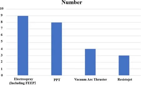
Figure 1.The number of satellites under 50 kg using different electric propulsion methods in the years 2006-2018 [4].
A PPT can use solid,liquid or gas propellant,however,all current PPT flight systems and products use solid propellant.In addition,most of the previous PPT studies are based on solid propellant.For convenience,PPTs using solid,liquid and gas propellants are abbreviated as SPPT,LPPT and GPPT,respectively,in this paper.
The traditional PPT uses parallel-plate electrodes and solid propellant.Figure 2 shows a schematic of a traditional PPT.A capacitor is used to store discharge energy.An ignitor(usually a spark plug) produces the initial plasma to trigger the capacitor discharge.The arc ablates the solid propellant to produce the neutral gas which can be ionized and become plasma in a high-voltage electric field.The plasma can maintain the discharge and be accelerated by pressure and electromagnetic forces to generate thrust [2].
A PPT system usually consists of a thruster,a PPU and a control unit.The thruster consists of electrodes,an energy storage device (usually a capacitor),ignitor,propellant with its feed system (usually a spring),transmission conductors that are used to connect the electrodes and the capacitor,a shell and structural parts.The PPU is used to convert the low voltage (usually under 28 V) supplied by a satellite to a high voltage above 1000 V for the PPT operation.The control unit is used to control the starting,closing and operating frequency of a PPT.To conserve size and weight,the PPU and control unit are usually integrated into the thruster shell.
2.1.Propulsion performance parameters
As a PPT is a pulsed thruster,its thrust is determined by the impulse bit and operation frequency.The thrust of a PPT can be calculated by the following equation:

where Ibitis the impulse bit,T is the thrust,f is the operation frequency,m is the ablated mass bit (the ablated mass produced by every pulsed thruster operation)and v is the velocity of the exhaust mass.
The specific impulse is calculated by:
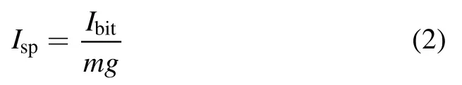
where Ispis the specific impulse,and g is the acceleration of gravity.

Figure 2.A schematic of a traditional PPT.
The efficiency of a PPT system is calculated by:

where η is the efficiency,T/P is the thrust-to-power ratio and P is the total electric power provided by the satellite.
As the power losses of the control unit and the ignitor are negligible,the system efficiency is determined by the PPU efficiency and the thrust efficiency
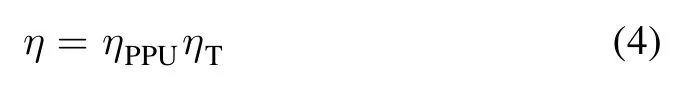
where ηPPUis the efficiency and ηTis the thruster efficiency.The thrust efficiency is calculated by:
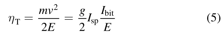
where E is the PPT initial capacitor energy.
2.2.Plasma production
According to the schematic of a traditional PPT (shown in figure 2),the solid propellant ablation and gas ionization are the key physical processes of the plasma production in a traditional PPT.The solid propellant ablation determines the neutral gas supply to the discharge chamber,and the gas ionization determines the propellant utilization.
According to past experimental results,approximately 10%-60%of the neutral gas can be ionized to plasma during a PPT discharge [7,8].As the exhaust speed of neutral gas(usually <500 m s?1) is much lower than the speed of the plasma (usually >30 km s?1),the thrust contribution of the neutral gas is usually negligible in a PPT [9,10].
It is assumed that the thrust contribution of the neutral gas is negligible.The velocity of the exhaust mass can be calculated by:
Equation (4) can be written as:
where ηPis the propellant utilization,miis the plasma mass and viis the plasma velocity.According to equation (7),the propellant utilization has a great influence on the total efficiency[11].The low propellant utilization is one of the major reasons for the low propulsion performance of PPTs.
2.3.Plasma acceleration
The discharge circuit of a PPT can be equivalent to an inductor-resistor-capacitor (LRC) circuit [2],shown in figure 3.
According to past studies [12],the consumption of the capacitor initial energy is calculated as:
where Re,Rcand Riare the resistances of the transmission conductors,capacitor and plasma,respectively,Liis the inductance of the plasma,and teand I are the discharge time and the discharge current.If the resistances of the transmission conductors and capacitor are too high,a large amount of energy will be consumed by the discharge circuit.
The voltage between the electrodes is calculated as:
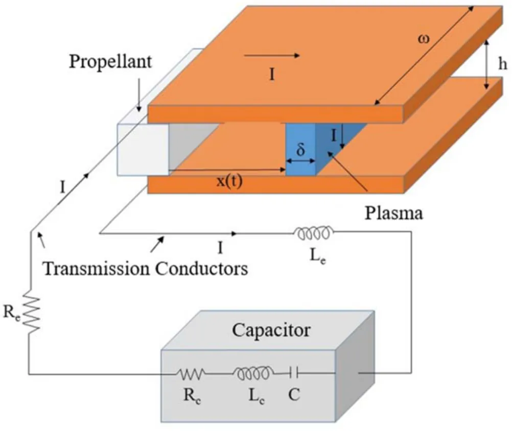
Figure 3.The discharge circuit of a parallel-plate PPT.
where Ueis the voltage between the electrodes and U is the capacitor voltage,and Leand Lcare the inductances of the transmission conductors and capacitor.According to research on ionization in gas,the ionization rate increases as the electric intensity increases.If the inductances of the transmission conductors and capacitor are too high,the voltage between the electrodes would be too low to obtain a high propellant utilization.
According to past studies,the impulse bit of a parallelplate PPT can be estimated by an empirical equation [12]:
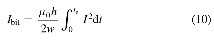
where h and w are the electrode gap and width,respectively,and μ0is the permeability of vacuum.
The solid propellant ablation,neutral gas ionization and plasma acceleration need energy.The energy distribution decides the efficiency and propellant utilization of a PPT.
3.Examples of existing PPTs
After 2005,most PPTs were applied to small satellites under 50 kg,especially CubeSats under 10 kg[4].Since 2007,more than ten small satellites using PPTs have launched and several organizations have developed various PPT products.This section will introduce some representative PPTs to show the performance of the PPT.Tables 1 and 2 present the design schemes and performances of PPT systems developed in recent years,respectively.In addition,aside from the PPT used in HuskySat-1,all of the PPTs introduced in this section use Teflon propellant.
As the power provided by small satellites under 10 kg is usually lower than 10 W [1]and many electrical propulsion systems (including ion and Hall thrusters) cannot work at power levels below 10 W,PPT systems working above and below 10 W are introduced separately in this section.
3.1.PPTs operating at power levels below 10 W
3.1.1.PPTCUP.The PPTCUP [14]was developed for CubeSat applications by MarsSpace Ltd,ClydeSpace Ltd and the University of Southampton.The total volume and mass of the propulsion system are only 100×100×33 mm3and 0.27 kg,respectively.It can operate at 2 W(1 Hz),and can provide an average specific impulse of 655 s.A total impulse of 48 Ns is generated by approximately 1.125×10⁶shots.The electrodes are approximately 5 mm wide with a flared angle of 15°.A side-fed propellant system is used to feed 8 g of Teflon propellant,and the 2 J main discharge energy is stored in eight 200 nF capacitors.The PPTCUP has passed thermal tests,mechanical tests,performance tests and electromagnetic compatibility (EMC)characterization tests.
3.1.2.BMP-220.The BMP-220[15]is a micro PPT thruster system developed by Busek Co.Inc.Its predecessor,MPACS,had successfully operated on the Falconsat-3 satellite that was launched in 2007.It includes 12 threeelectrode coaxial PPT sticks and all associated command,control and power circuitry within a compact package.The system power of the PPT unit is 3 W at 1 Hz.The total mass of the BMP-220 is less than 0.5 kg,and a total impulse of 175 Ns can be provided from the Teflon propellant.The average impulse bit is approximately 20 μN(yùn)s.
3.1.3.LPPT-5.The LPPT-5[16]is a PPT system which was developed by the Lanzhou Institute of Physics.It is planned to be used in a 12 U CubeSat.The input power of the system is 5 W.The PPT can provide an impulse bit of 40 μN(yùn)s and a specific impulse of approximately 600 s.The total impulse of the PPT unit is approximately 60 Ns.
3.1.4.PROITERES1 PPT.PROITERES1 [17]is a 15 kg nanosatellite that was developed by the Osaka Institute of Technology.It is equipped with an electrothermal PPT system that can provide 5.4 Ns total impulse (50 000 shots at 1 Hz).The PPU of this system consumes 5 W of power.A 1.5 μF capacitor is used to store energy.The satellite was launched in 2012.
3.1.5.Pegasus PPT.The 1 U CubeSat Pegasus [18]was developed in Austria.It was launched with a PPT unit in 2017.The PPT unit uses four thruster heads to provide approximately 6.8 Ns of total impulse.The discharge energy and specific impulse of this PPT are approximately 1.8 J and 904 s,respectively.The unit consumes approximately 2.5 W of power (1 Hz discharge frequency) and weighs 294 g.
3.1.6.AOBA VELOX-IV PPT.The 2 U CubeSat AOBA VELOX-IV (AV4) [19]was developed by Nanyang Technological University and Kyushu Institute of Technology.A PPT system is used for attitude control,orbit maintenance and momentum dumping.Its predecessor had been used for orbit maintenance on AOBA VELOX-III(AV3) [20],which was launched in 2016.The lifetime of AOBA VELOX-III increased from three months to six months because the PPT provided thrust to compensate the drag at low Earth orbit (LEO).The PPT system on AOBA VELOX-IV used four heads to increase the total impulse to approximately 150 Ns.The 0.5 U PPT unit consumes 2.25 W power to provide an impulse bit of 25.2 μN(yùn)s and a specific impulse of approximately 676 s.AOBA VELOX-IV was launched in January 2019.
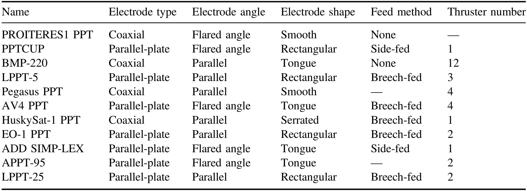
Table 1.The design schemes of the PPT systems presented in this section [14-26].
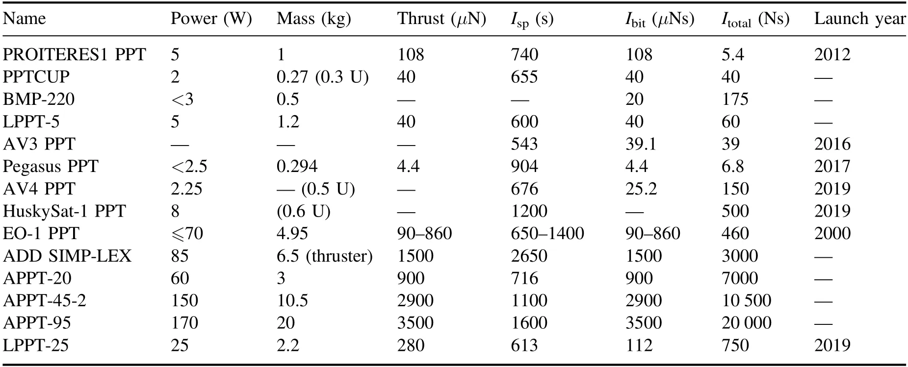
Table 2.The performance of PPT systems developed in this section [14-26].
3.1.7.HuskySat-1 PPT.A 3 U CubeSat named the HuskySat-1 [21]was developed by students from the University of Washington.A 0.6 U PPT unit will be tested on this 5 kg CubeSat.The PPT system is characterized by a high thrust-to-power ratio of 45 μN(yùn) W?1,a specific impulse of approximately 1200 s and a thrust efficiency of 25%at 20 J discharge energy.Solid sulfur propellant and a serrated coaxial cathode are used to improve the PPT performance.The thruster unit consumes 8 W of power and carries 50 g of fuel for a total impulse of approximately 500 Ns.The HuskySat-1 was launched in November 2019.
3.2.PPTs operating at a power level above 10 W
3.2.1.EO-1 PPT.The EO-1 (Earth Observing-1) satellite[22]was launched in 2000.It weighs 529 kg and uses a PPT system to perform attitude control.The PPT system can provide an impulse bit of 90-860 μN(yùn)s,a total impulse of 460 Ns and a specific impulse of 900-1400 s.Its operation frequency is 1 Hz.It weighs 4.95 kg and consumes 70 W(maximum discharge energy) of power.
3.2.2.ADD SIMP-LEX.The iMPD thruster ADD SIMP-LEX[23]is a PPT system operating at 85 W and 1 Hz frequency.This PPT system was developed by the Institute of Space Systems in Stuttgart (IRS) and can provide an impulse bit of 1.5 mNs.The total ignition number of this system is approximately 2 million for generating a total impulse of 3000 Ns.The electrodes are tongue shaped with an approximate 21 mm gap and a flared angle.The specific impulse and thrust efficiency of the PPT are 2650 s and 30%,respectively.
3.2.3.APPT propulsion systems developed by RIAME.A series of APPT (ablative PPT) electric propulsion systems[24]were developed by the Research Institute of Applied Mechanics and Electrodynamics (RIAME).The operation powers of these APPT systems range from 16 to 170 W[24].The performances of these APPTs are shown in table 2.Among these thrusters,APPT-95 is planned to be applied to five LEO small satellites weighing 400-500 kg.Some designers proposed a hybrid electric propulsion system based on the steady plasma thruster (SPT,a type of Hall thruster) and APPT [25].The SPT is used for corrections of the working orbit.The APPT is used to increase thrust precision.
3.2.4.LPPT-25.A 25 W PPT system named the LPPT-25[26]was developed by Lanzhou Institute of Physics.This 2.2 kg unit can provide a thrust of 0.28 mN and a specific impulse of 613 s.Two thruster heads are used to generate a total impulse of 750 Ns.LPPT-25 finished on-orbit testing in September 2019 (tables 1 and 2).
4.Performance improvement
Low thrust efficiency is the largest disadvantage of PPTs.The efficiency of a PPT system is usually less than 10% [7].To improve the performance of PPTs,a large number of experimental studies have been carried out,and the main results are summarized as follows.
4.1.Electrodes
Electrodes have an important influence on the performance of a PPT.The electrodes of PPTs can be divided into two types:the parallel-plate type,and the coaxial type.
4.1.1.Parallel-plate electrodes.The parallel-plate type is the most common type of PPT electrode.A parallel-plate PPT is shown in figure 2.According to past studies [27],with an increasing electrode gap,the specific impulse of a PPT increases while the thrust-to-power ratio decreases.On the other hand,the PPT propulsion performance increases by increasing the electrode flare angle from 0° to 20° but decreases when the electrode flare angle increases from 20°to 30° [27,28].Tongue-shaped electrode PPTs have better performance than rectangular-shaped electrode PPTs [28].According to equation (10),the electrode gap-to-width ratio has a great effect on the PPT performance.At the same current wave,the average electromagnetic force increases as the electrode gap-to-width ratio increases.However,the plasma resistance also increases as the electrode gap-to-width ratio increases and leads to a lower average current,which opposes the electromagnetic acceleration in PPTs.The gap,flared angle and shape determine the average electrode gap-to-width ratio and should be set to suitable values for a high-performance PPT.
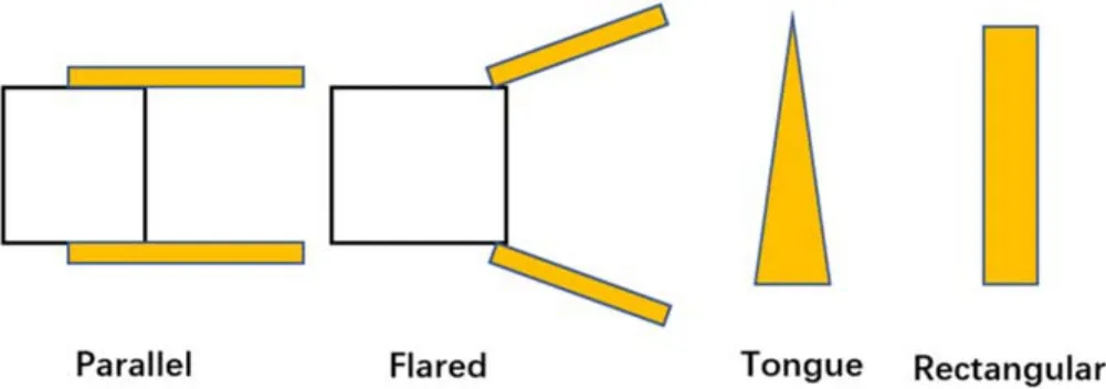
Figure 4.Types of parallel-plate PPT electrodes.
In recent years,some new designs of the parallel-plate PPT electrodes,such as asymmetric electrodes [29,30]and segmented electrodes [31],have been proposed to improve PPT performance (figure 4).
4.1.2.Coaxial electrodes.The coaxial PPT electrodes can be divided into the inner-outer type and the front-back type.The plasma in inner-outer electrode coaxial PPTs is accelerated mainly by electromagnetic force,and the plasma in frontback electrode coaxial PPTs is accelerated mainly by gas expansion.In most papers,the front-back electrode coaxial PPT is called an electrothermal PPT [17](figure 5).
The experimental and theoretical studies of coaxial PPTs are relatively deficient compared to those of parallelplate PPTs.For the inner-outer type,the diameter of the thruster head ranges from 3 mm to 50 mm [32,33].The diameter of a front-back coaxial PPT is usually approximately 20 mm [34].For a front-back electrode coaxial PPT(electrothermal PPT),with the increase in propellant length,the specific impulse increases while the thrust-to-power ratio decreases [35].
A flared angle can be used to enhance the gas expansion acceleration of a coaxial PPT.A serrated coaxial cathode[21]has been proposed in recent years.Experimental results show that the thrust-to-power ratio of a coaxial cathode PPT increases when using a serrated electrode (figure 6).
4.2.Discharge circuit
The initial electrode voltage,capacitance,operation frequency,inductance and resistance of the discharge circuit affect the performance of a PPT.According to equations (8)and (9),the inductance and resistance of the PPT external circuit (transmission conductors and capacitor) should be as small as possible to achieve a higher efficiency.
The thrust of a PPT can be estimated by the following equation:
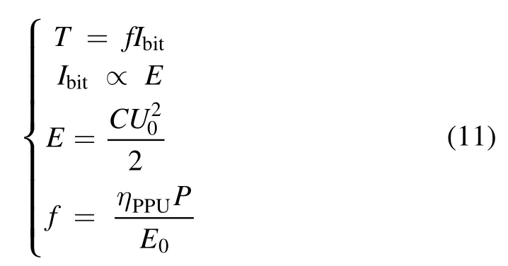
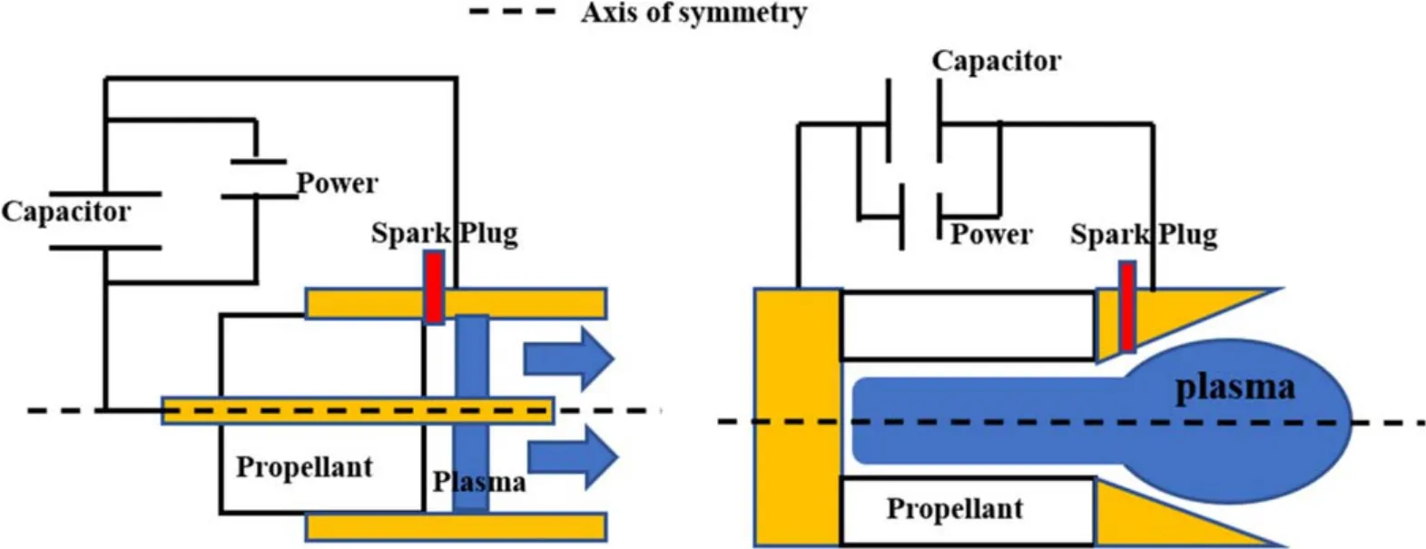
Figure 5.The inner-outer (left) and front-back (right) coaxial PPTs.
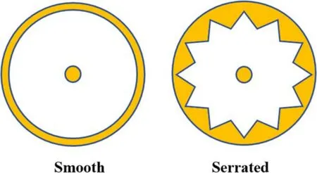
Figure 6.Traditional (left) and serrated (right) coaxial PPT electrodes.
where Ibitis the impulse bit,T is the thrust,f is the operation frequency,E is the capacitor energy,P is the power of the PPT system,C is capacitance,U0is the initial capacitor voltage and ηPPUis the electric efficiency of the PPU.It can be seen that a given PPT thrust can be obtained by different operation frequencies and capacitor energy under a given power.In addition,a given discharge energy of a PPT can be obtained by different initial capacitor voltages and capacitances.
The past experimental results show that the propulsion performance of a PPT usually increases with an increasing PPT discharge energy [36].However,a higher discharge energy needs a larger and heavier capacitor,which may offset the benefits from high propulsion performance.
At a given discharge energy,a PPT will exhibit different performances when using different capacitances.Nawaz et al studied the effect of capacitance variation on a parallel-plate PPT at a given 17 J discharge energy[37].Four capacitances of 20 μF,40 μF,60 μF and 80 μF were chosen.The results showed that the highest impulse bit and thrust efficiency were gained at 60 μF capacitance.
The operation frequency also affects the performance of a PPT.In 2007,the effect of operation frequency on a parallelplate PPT was studied by Antropov et al [38].The results showed that the efficiency of the PPT increased by increasing the operation frequency from 3 Hz to 10 Hz,but decreased by increasing the operation frequency from 10 to 20 Hz.
4.3.Propellant material
The propellant material is an important factor which affects the performance of a PPT.At present,Teflon is the preferred propellant of PPTs because it has stable temperature and insulation characteristics [27].However,the performance of Teflon PPTs is low.In addition to Teflon,many kinds of modified propellant have been studied to improve the performance of PPTs.
4.3.1.Gas and liquid propellants.A PPT can use solid,liquid or gas propellant because of its pulse discharge method.LPPTs need valves,injectors and vessels to feed or store their liquid propellants.Discharge is used to ablate the liquid to produce neutral gas [39].At present,PPTs using various liquid propellants have been studied.The propellants include water,methanol,mercury and so on [40-42].Among these liquids,water is the most-studied propellant [39].Most LPPTs need heaters because their propellants (such as water and mercury)might require heating to remain liquid in space.As the heater increases the weight,volume,power and unreliability of a PPT,the nonvolatile liquid propellants(such as mineral oils,silicone oils and perfluoropolyether) were proposed [43].These liquid propellants have a low evaporation rate in vacuum up to 100°C-150°C.These nonvolatile liquid propellants can be stored in a tank or a porous material block and can be fed by an open capillary or vacuum impregnation [43,44].
The development of GPPTs started in the early 1960s[39].These PPTs need fast-acting valves,injectors and highpressure vessels to feed or store their gases.The propellant of a GPPT is usually xenon,nitrogen or argon [39].In recent years,research has focused on airbreathing electric propulsion because this propulsion system does not need to carry onboard propellant.Some airbreathing PPTs have also been developed and tested.The experimental results show that the thrust-to-power ratio of an airbreathing PPT can be higher than 350 mN W?1at altitudes of ~25 km [45].
According to past studies,using liquid or gas propellant can increase the specific impulse and efficiency of a PPT[39].In addition,as the area of the PPT discharge surface is small(usually less than 10 cm2),a solid propellant block could be very long for a high total impulse mission.A PPT using liquid or gas propellant does not have this problem because it can use a large vessel to store a large amount of propellant to provide a very high total impulse.
However,three problems restrict the applications of GPPTs and LPPTs.First,a much more complex propellant feed system that consists of valves,injectors,storage,pipes and a control circuit is needed in a GPPT or LPPT.The complex propellant feed system will increase the weight,volume,power,insecurity and unreliability of a PPT system.Second,the operation time of a GPPT or LPPT feed system is always ms in magnitude,which is much longer than the PPT discharge time (μs in magnitude).Therefore,many propellants are wasted because the feed system cannot close immediately after the PPT discharge ends.Finally,the performance of a GPPT or LPPT is still lower than that of an ion or Hall thruster.Therefore,GPPT and LPPT systems are uncompetitive for high total impulse missions (such as deep space missions).On the other hand,for low total impulse missions,the solid propellant is more suitable because it is fed by a simple system and has a relatively high density.
4.3.2.Alternative solid propellants.In 1976,Palumbo et al studied the propulsion performances of a PPT using other thermoplastic (Celcon,Halar,Tefzel and Halon) propellants and Teflon propellants that were seeded with LiOH and InBr[20].Over the next 40 years,various solid propellants[46-50](including porous Teflon,high-density Teflon,carbon-impregnated Teflon,copper-impregnated Teflon,aluminum-impregnated Teflon,chemical propellant and so on)were studied.Some of them seem to have good effects on improving PPT performance.However,considering the reliability,no PPTs without Teflon were applied to spacecraft before 2019.In 2019,a PPT using a sulfur propellant was launched with a 3 U CubeSat named HuskySat-1 [21].According to the experimental results,the thrust-to-power ratio of a PPT using sulfur is nearly twice that of the same PPT using Teflon.
In recent years,some researchers proposed a PPT that can utilize environmental resources(such as space debris[51]and asteroid regolith [52]) to reduce the onboard propellant.
4.4.Energy discharge method
The energy of a traditional PPT is stored in a capacitor and released by discharge.The energy used for propellant ablation,gas ionization and plasma acceleration cannot be adjusted for a high performance.For example,the late-time ablation issue[8]is one of the consequences of the inefficient energy distribution of PPTs.After a pulse discharge ends,the PPT propellant surface temperature is still above the decomposition temperature and the neutral gas is still produced.This phenomenon is called late-time ablation.The gas produced after the discharge cannot be accelerated by the Lorentz force and has a very low speed.The late-time ablation can be considered a consequence of ablation energy spilling,and will greatly reduce the propellant utilization of a PPT.
The multiple discharge method [53]is proposed to solve this problem.A multi-discharge PPT stores its energy in two or more capacitors and discharges at different positions and times.The PPT energy distribution can be adjusted in this way.
Okada et al developed a double-discharge PPT to solve the late-time ablation issues [54].The secondary discharge is expected to ionize and accelerate some late-time neutral gas from the primary discharge.In 2009,Marques et al developed a two-stage PPT[55]that stored the energy to two capacitors and discharged at different positions.The authors also expected that the late-time-ablated gas could be ionized between the secondary stage electrodes.However,as the optimizations of these thrusters were not satisfactory,the highest efficiency was still below 10% (figure 7).
To study the optimization of the energy distribution in PPTs,a double-discharge PPT [13]was developed and studied by Wu et al.The experimental results showed that the new PPT performance was improved compared to a singledischarge PPT.The specific impulse and thrust efficiency of the PPT increased as the secondary capacitor energy increased when the total energy remained constant [13].
4.5.Propellant feed method
According to past studies,the propellant feed method affects the performance of a PPT using solid propellant.
For parallel-plate SPPTs,propellant feed methods can be divided into the breech-fed type and the side-fed type.Palumbo and Gumant studied the effect of the feed method on SPPT performance [27].The results showed that the breechfed SPPT has a higher specific impulse and efficiency but a lower thrust-to-power ratio than the side-fed SPPT(figure 8).
The propellant feed method of a coaxial SPPT is usually the breech-fed type.However,some micro coaxial SPPTs do not use feed systems.These SPPTs are simpler and more reliable because they contain no moving parts.However,the impulse bit of an SPPT without a feed system declines as the discharge number increases because of the discharge surface moving [35,56].
4.6.Ignition method
A PPT usually uses a spark plug to trigger the main discharge.However,some researchers [47,48]have used laser systems to replace spark plugs.It is found that the laser-assisted PPTs have higher efficiencies and specific impulses.In 2015,Matsubara et al designed a short-pulse laser-assisted PPT[57].The PPT used Al2O3as its propellant.According to the experimental results,the maximum specific impulse and maximum thrust efficiency of the short-pulse laser-assisted PPT were 4000 s and 15%,respectively[57].In 2016,Zhang et al developed a novel laser-assisted PPT[58].For the Teflon propellant,the experimental results showed that the specific impulse and the thrust efficiency of the novel laser-assisted PPT were 2400 s and 16%,respectively [58].
However,a laser system will add weight,power and volume to a PPT system.This is against the applications of laser-assisted PPTs in low total impulse missions.At present,the laser-assisted PPT is at the laboratory research stage(figure 9).
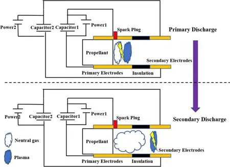
Figure 7.A schematic of a double-discharge PPT [13].
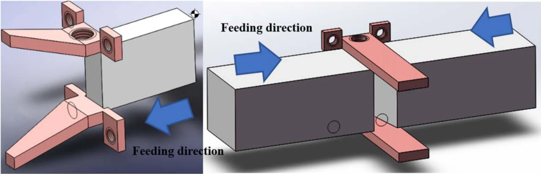
Figure 8.A schematic of a breech-fed (left) and side-fed (right) PPT.
4.7.Number of thruster heads
For a single-head PPT system,the shape of the solid propellant will be too long for a high total impulse mission.To solve this issue,some SPPT systems(such as BMP-220[15],AOBA VELOX-IV PPT [19],LPPT-25 [25]and PROITERES2 PPT[59])use multiple thruster heads.In these SPPT systems,more than two thruster heads are connected to the same capacitor.These thrusters work at the same time[59]or work in turn [15,19].For example,in the SPPT system of AOBA VELOX-IV [19],four PPT heads all align with the long axis and fire in certain sequences to provide a relatively stable thrust.A 5.72 g Teflon propellant block is carried by each head to meet the one-year mission’s requirements(approximately 150 Ns) (figure 10).
5.Lifetime and reliability
Lifetime and reliability are very important to a PPT system.However,studies about these aspects are deficient.As gas and liquid propellant PPTs are still in experimental stages,most of the studies about PPT lifetimes and reliability are based on Teflon propellant.The ignitor,ignition process and propellant carbonization are the main factors influencing the PPT lifetime and reliability.
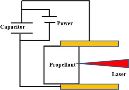
Figure 9.A schematic of a laser-assisted PPT.
5.1.Ignitor
The ignitor is used to trigger the main discharge of a PPT[60].A spark plug is the most commonly used ignitor.Over the past 50 years,the requirements,design methods,circuit optimization and lifetime improvement of spark plugs used in PPTs have been studied and many results can be referenced [61,62].
A micro coaxial PPT can be discharged without an ignitor[63].However,for a self-triggered PPT,the discharge voltage is very high(usually above 6 kV)and unstable,which goes against the PPU design and generates a stable impulse bit [63].On the other hand,a spark plug is too large for a micro coaxial PPT whose diameter is 3-10 mm.To solve this problem,a three-electrode structure [64]was proposed.The three-electrode structure can reduce the discharge voltage of a coaxial PPT from 40 kV to approximately 3 kV [64].In addition,the discharge voltage will be stable in a three-electrode PPT because the main capacitor discharge is triggered by the discharge between the intermediate and center electrode.A three-electrode PPT system developed by Busek Co.Inc.was launched on FalonSat-3 in 2007 [15](figure 11).
A laser-assisted method[57,58]is an alternative method for igniting the main discharges of PPTs.Of course,the laser system is still too heavy and large for a PPT system at present.
5.2.Ignition process
The ignition process of a PPT is actually a breakdown of the insulator,liquid or gas between electrodes.However,the PPT ignition is different from the usual breakdown because the initial charged particles come from an ignitor instead of the field emission.Therefore,the breakdown electric field between the PPT electrodes is below 100 V mm?1,which is much lower than that of the usual breakdown (usually above 1000 V mm?1) [2].
The ignition process has been in focus in recent years for the optimization of multi-discharge PPT designs.According to the experimental studies[65]of the PPT ignition process,a time delay (μs magnitude order) exists between spark plug ignition and capacitor discharge.The time delay increases with an increasing electrode gap,an increasing discharge number and a decreasing capacitor voltage.In addition,the discharge success rate of a PPT increases as the capacitor voltage increases,and decreases as the discharge number and the electrode gap increase [66].
5.3.Propellant carbonization
The PPT propellant material is usually Teflon,which can produce carbon by arc ablation [67,68].As the discharge number increases,more carbon can deposit on the propellant surface of a PPT.Too much carbon can connect the electrodes and lead to a short circuit of a PPT.
This carbonization is one of the major lifetime limitations of a PPT using Teflon propellant.Increasing the discharge energy per ablation area is an effective means to reduce this phenomenon[69].In addition,some new propellants,such as sulfur [21]and nonvolatile liquid [70-73],can be used to replace Teflon to reduce or avoid propellant carbonization.
6.Modeling
Over the past 50 years,many numerical models of PPTs have been developed.Some of them were established to estimate the PPT performance.The others were mainly used to study the working mechanisms of PPTs because some physical parameters are difficult to measure.Most of the models of PPTs are based on Teflon propellant.A traditional PPT model usually consists of a circuit sub-model,an ablation submodel,an ionization sub-model and an acceleration submodel.Of course,a GPPT model does not have an ablation sub-model.In this section,the development of these PPT submodels will be introduced.
6.1.Circuit model
The circuit model is used to obtain the discharge current and capacitor voltage during a PPT discharge.The discharge current and capacitor voltage are important inputs and feedbacks to other sub-models.For a PPT,its discharge circuit can be equivalent to an LRC circuit,and the discharge current and capacitor voltage can be obtained by [74,75]:
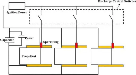
Figure 10.A schematic of a multi-head PPT.
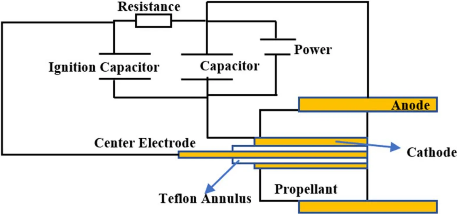
Figure 11.A schematic of a three-electrode PPT.
where R and L are the total resistance and inductance of the circuit.Here,Q(t),U(t)and I(t)are the capacitor electricity quantity,the capacitor voltage and the discharge current at time t,while U0and C are the initial voltage and capacitance of the capacitor,respectively.
The total inductance is the sum of the capacitor inductance,the conductor inductance and the plasma inductance.The total resistance is the sum of the capacitor resistance,the conductor resistance and the plasma resistance.As the plasma resistance and inductance are changing during the PPT discharge process and are difficult to compute,some PPT models[74,75]estimate them based on experimental data.
6.2.Ablation model
The solid propellant ablation of an SPPT determines the neutral gas supply to the discharge chamber.An ablation model of SPPTs can be used to obtain the gas inlet conditions and the thermal parameters of the propellant surface.
The modeling of the SPPT ablation process has been studied for a long time,and various models[76-79]based on different theories were developed for investigating the ablation mechanism of SPPTs.However,as this process is too complex and affected by other physical models (such as the circuit model and the acceleration model) of an SPPT,the ablated mass bits estimated by those ablation models cannot show good agreement with experimental results.Therefore,some SPPT models [74,80],which do not need to focus on the ablation process,will estimate the neutral gas parameters based on experimental data.For example,the slug model[74]assumes that all of the gases are produced at the beginning of the SPPT discharge and are located on the propellant surface.
For a GPPT model,the propellant supply is usually given according to the feed system of the PPT [74].For an LPPT model,an ablation model is still needed to simulate the evaporation of liquid.The modeling method of liquid ablation is similar to that of solid ablation [81].
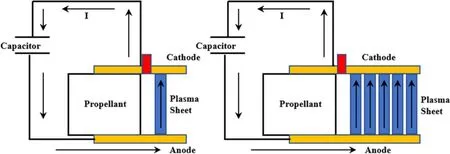
Figure 12.Schematics of the slug model (left) and the multi-sheet model (right).
6.3.Gas ionization model
The neutral gas ionization process has a great influence on the specific impulse and efficiency of a PPT [82].However,the ionization process is ignored in most PPT models.The neutral gas ablated from the propellant surface is usually assumed to be fully ionized [74,77].The full ionization assumption greatly reduces the precision of a PPT model.
Huang et al developed a PPT model that can simulate the process of ionization in a PPT[75,83].This model presumes that the neutral gas will be ionized and become plasma if the ionization condition is met.The ionization condition is assumed based on electron collision ionization theory.The propellant utilizations estimated by this model are in good agreement with the past experimental results of three PPTs [75].
6.4.Plasma acceleration model
The magnetohydrodynamic (MHD) model [84]and slug model [74]are the most frequently used models for simulating the plasma acceleration processes of PPTs.
The slug model (shown in figure 12) assumes that all of the plasma forms a sheet that has no mass loss or shape change while it is accelerated between the electrodes of a PPT.This model can be used to simply estimate the propulsion performance of a PPT.Based on the plasma sheet assumption,Huang proposed a multi-sheet model[75].In the multi-sheet model,it is assumed that the plasma sheets are generated near the propellant surface one by one during the PPT discharge.The discontinuities of the plasma flow in PPTs can be represented by the multi-sheet model.
The MHD model [84]is established based on the local thermodynamic equilibrium and continuum assumptions.In this model,the thermodynamic equations and ideal MHD equations are solved to obtain the physical parameters (such as plasma density and temperature) between the PPT electrodes.The propulsion performance can also be estimated by the MHD model.
The particle-in-cell and Monte Carlo (PIC/MC) method[85]can be used to simulate the collisions and movements of particles to obtain the plasma and electrical parameters in an electric thruster.This method is used widely in some steadythrust electric thruster (such as Hall thrusters [86]) simulations.However,a PPT PIC/MC model is very difficult to develop because the background gas,electric field and magnetic field distributions between the PPT electrodes are unsteady during the discharge process.Although the precision is still low at present,some PPT [87,88]models based on the PIC/MC method have been developed.More reasonable assumptions are needed for a high precision PPT PIC/MC model.
7.Conclusions
As the first electric propulsion technique used in space missions,the PPT still plays an important propulsive role in the space propulsion field.Despite their typically low efficiency and specific impulse,PPTs are suitable for small satellite propulsion missions,for which a light weight,small volume,lost cost and low power consumption are more important.For propulsion missions of nanosatellites (under 10 kg),a PPT system is very competitive because of its high reliability and low cost.As the total impulse requirement increases,the competitiveness of a PPT reduces because of the limitations of its low specific impulse,total discharge number and propellant feed ability.To further improve the competitiveness of PPTs and expand their application range,the following studies should be carried out in the future.
(1) Even though PPTs have been studied for more than 50 years,there is much room for its performance to improve.Previous studies have shown that some new methods(such as a multi-discharge design)can improve the specific impulse and efficiency of a PPT.The engineering applications of these new methods should be promoted.
(2) Studies on the lifetime and reliability of PPTs are deficient.Related theoretical and experimental studies should be carried out for reliability evaluations and lifetime predictions of PPTs.
(3) Further studies on PPT modeling are needed to improve the simulation precision.The development of a precision model that can simulate the propellant ablation,gas ionization and plasma acceleration process is still a valuable and challenging task to PPT researchers.
Acknowledgments
This work was supported by National Natural Science Foundation of China (No.11672039).
 Plasma Science and Technology2020年9期
- Plasma Science and Technology的其它文章
- Special issue on selected papers from CEPC 2019
- Life test research of a high specific impulse Hall thruster HEP-140MF
- Magnet stage optimization of 5 kW multicusped field thruster
- Simulation study on the influence of magnetic field in the near-anode region on anode power deposition of ATON-type Hall thruster
- Numerical simulation of the plasma acceleration process in a magnetically enhanced micro-cathode vacuum arc thruster
- Discharge instability in a plasma contactor