
Numerical prediction of effective wake field for a submarine based on a hybrid approach and an RBF interpolation*
2017-09-15 13:55:50ZhiqiangRao饒志強ChenjunYang楊晨俊
水動力學研究與進展 B輯 2017年4期
關(guān)鍵詞:志強
Zhi-qiang Rao (饒志強), Chen-jun Yang (楊晨俊)
Collaborative Innovation Center for Advanced Ship and Deep-Sea Exploration, Shnaghai 200240, China State Key Laboratory of Ocean Engineering, Shanghai Jiao Tong University, Shanghai 200240, China, E-mail: hellostar@126.com
Numerical prediction of effective wake field for a submarine based on a hybrid approach and an RBF interpolation*
Zhi-qiang Rao (饒志強), Chen-jun Yang (楊晨俊)
Collaborative Innovation Center for Advanced Ship and Deep-Sea Exploration, Shnaghai 200240, China State Key Laboratory of Ocean Engineering, Shanghai Jiao Tong University, Shanghai 200240, China, E-mail: hellostar@126.com
A hybrid approach coupled with a surface panel method for the propeller and a Reynolds averaged Navier-Stokes (RANS) model for the hull with the propeller body forces are presented for predicting the self-propulsion performance and the effective wake field of underwater vehicles. To achieve a high accuracy and simplicity, a radial basis function (RBF) based approach is proposed for mapping the force field from the blade surface panels to the RANS model. The effective wake field is evaluated in two ways, i.e., by extrapolation from the flat planes upstream of the propeller disk, and by direct computation in a curved surface upstream of and parallel to the blade leading edges. The hull-propeller system of a real propeller geometry is further simulated with the sliding mesh model to numerically verify the hybrid approach. Numerical simulations are conducted for the fully appended SUBOFF submarine model. The high accuracy of the RBF-based interpolation scheme is confirmed, and the effective wake fraction predicted by the hybrid approach is found consistent with that obtained by the sliding mesh model. The effective wake fractions predicted by the two methods are, respectively, 4.6% and 3% larger than the nominal one.
Submarine, effective wake, panel method, Reynolds averaged Navier-Stokes (RANS), radial basis function (RBF)
Introduction
The effective wake distribution is an important factor in designing the wake-adapted propellers. But nominal wakes and waves on free surface are still hot spots in ship and offshore structure engineering[1-4]since it is impossible to obtain effective wake distribution experimentally. Usually one has to predict it empirically with the nominal wake distribution and the effective wake fraction, which are both obtained from model tests along with scale effect corrections. In this context, and owing to the rapid progress in the computational fluid dynamics (CFD), the numerical prediction of the effective wake distribution becomes possible and has attracted the attention of the ITTC[5].
To our knowledge, all numerical predictions of the effective wake are based on the viscous flow CFD simulation of self-propulsion, combined with bodyforce models built on different potential flow propeller models or just empirical formulas. The action of the propeller behind the ship hull is represented by a body force distribution acting on a cell zone, which is either the propeller disk, a circular cylinder, or a cylinder swept out by the rotating blades. Wu et al.[6]and Fu et al.[7]analyzed the self-propulsion performance of the container ship KCS with the body force models, in which the forces of the propeller were expressed approximately by an empirical analytic function. Tahara et al.[8]evaluated the self-propulsion characteristics of the KCS using overset grids. The force field of the propeller was predicted with an infinite-blade propeller model. Sanchez-Caja et al.[9]analyzed a counter rotating propeller (CRP) unit by coupling the Reynolds averaged Navier-Stokes (RANS) and liftingline models. A correction method was proposed in the study of the CRP unit to improve the prediction accuracy of the propeller induced velocities. Sakamotoet al.[10]carried out numerical and experimental studies of a twin-skeg container ship using a simplified propeller theory to predict the propeller forces. The simulated resistance and the self-propulsion performance were close to the experimental results. In the studies of the KCS ship by Zheng et al.[11]and Yang et al.[12], the body forces were determined by a vortex lattice method and a panel method, respectively. In the preceding studies, the body forces were acted upon the fluid in a circular cylindrical zone, which can be quite different from the actual geometry of the propeller blades. Tian et al.[13]combined the vortex lattice method and the RANS simulation to predict the effective wakes of ducted propellers. A conservative interpolation scheme (CIS) with high accuracy was adopted for the force field interpolation from the potential flow to the RANS simulation. Villa et al.[14]studied the self-propulsion performance of the KCS ship by using an actuator disk model and a coupled viscous/inviscid flow method. Starke et al.[15]and Rijpkema et al.[16]presented a hybrid RANS and boundary element method (BEM) to determine the effective wake of the KCS ship. An interpolation scheme was proposed to map the body force field from BEM to RANS grids. In Refs.[13-16], the body force zone takes the shape of a cylinder swept out by the blade outlines, which allows the body forces to act on their actual locations. These studies all focused on surface ships. For underwater vehicles, the effective wake field is more important for designing low-noise propellers, however, there is a lack of related studies.
In this paper, the effective wake of a fully appended SUBOFF is predicted based on a hybrid approach coupled with a surface panel method and the RANS simulation. To achieve a high accuracy and simplicity, a radial basis function (RBF) based approach is proposed for mapping the force field from the blade surface panels to the RANS grids. The effective wake field is determined in two ways, i.e., by extrapolation from the planar transverse sections upstream to the propeller disk, and by direct computation in a curved surface which is upstream of and parallel to the surface swept out by blade leading edge. The hullpropeller system of a real propeller geometry is further simulated with the sliding mesh model to verify the hybrid approach. The high accuracy of the RBF-based interpolation scheme for the body force field is confirmed, and the predicted effective wake fractions based on the hybrid approach and the sliding mesh model are found consistent.
1. Numerical method
1.1 Hull resistance and nominal wake simulation
To validate the present approach for the viscous flow simulation, the resistance and the nominal wake of the fully appended SUBOFF are predicted based on a steady RANS model. The standardk-εmodel and the standard wall function are employed for the turbulence closure. The SIMPLE algorithm and the second-order upwind schemes are adopted for the pressure-velocity coupling and the spatial discretization, respectively. Numerical computations are carried out by using the ANSYS FLUENT software. A grid dependency study is conducted first with three sets of block-structured grids and a refinement ratio ofin circular cylindrical domains of identical size. The distances from the inlet to the bow, from the outlet to the stern, and from the central axis of the hull to the lateral boundary are, respectively,L, 2Land 10Dm, whereLandDmdenote the overall length and the maximum diameter of the hull, respectively. Figure 1 shows the grids on the hull surface.
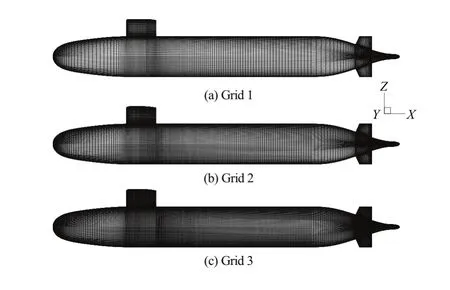
Fig.1 Grids on hull surface of SUBOFF
Table 1 shows the errors, as compared with the experimental data, of the calculated resistance at the model speedVm=3.051m/s and the Reynolds numberThe averagedy+of the walladjacent cells over the hull surface is about 50. It is seen that the maximum error is 3%, and the prediction error decreases with the increase of the number of cells.
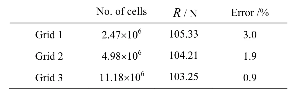
Table 1 Comparison of resistance prediction results using different grids
The comparisons of the simulated and measured nominal wake fields in the propeller plane (longitudinal locationx/L=0.978 withx=0 at thebow) are shown in Fig.2. The predicted nominal wake field is found quite consistent with the experimental one. Grid 2 is chosen for the following simulations in this paper as a compromise between the computational cost and the reliability of the simulated wake field.
The resistances in a range of speeds by using Grid 2 are computed and plotted in Fig.3 and compared with the experimental data, which shows that the maximum error is within 3% in the speed range. The averaged+yof the wall-adjacent cells is about 50-150.
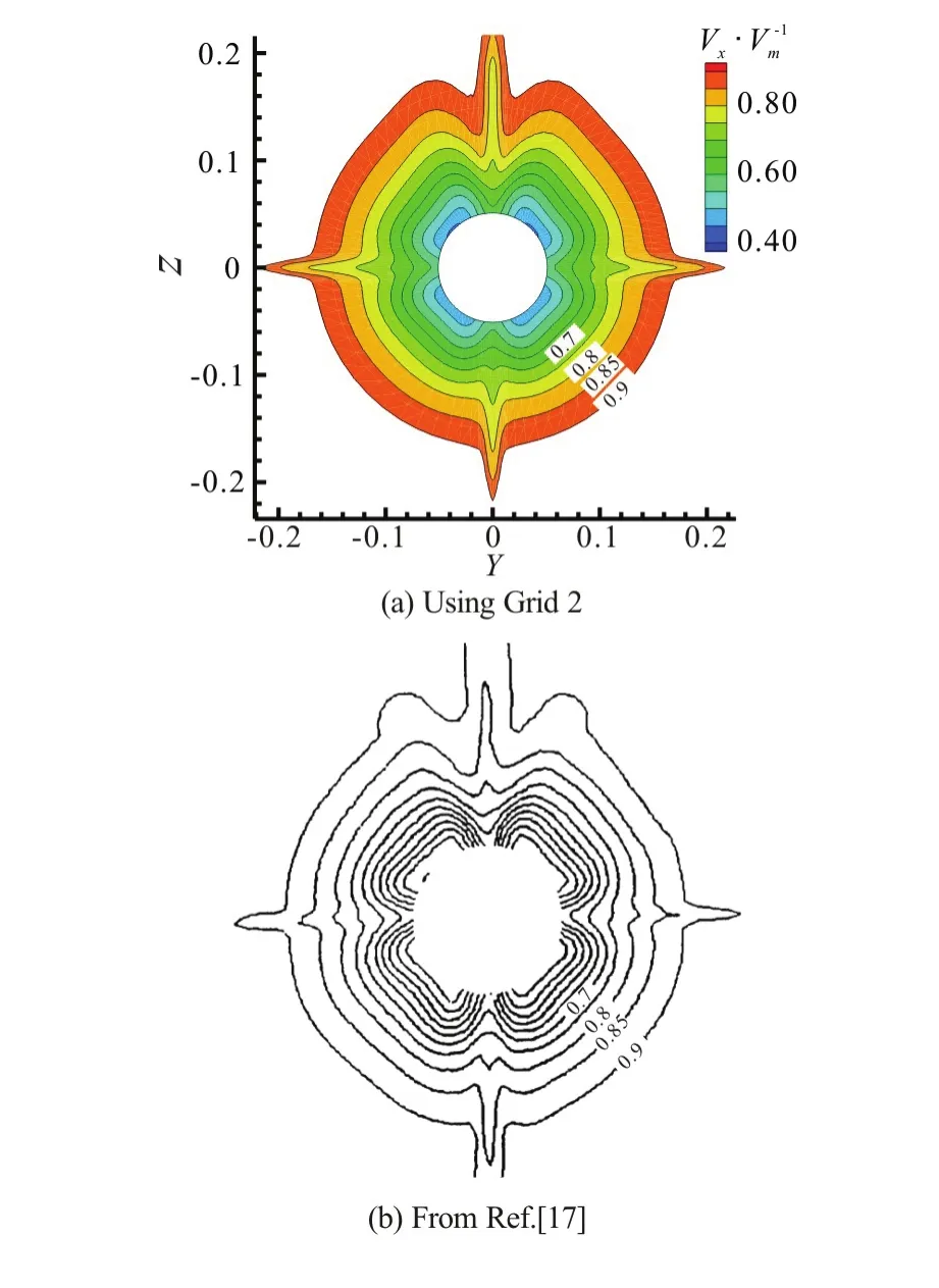
Fig.2 (Color online) Comparison of calculated and measured axial velocities at propeller plane
1.2 Hull resistance and nominal wake simulation
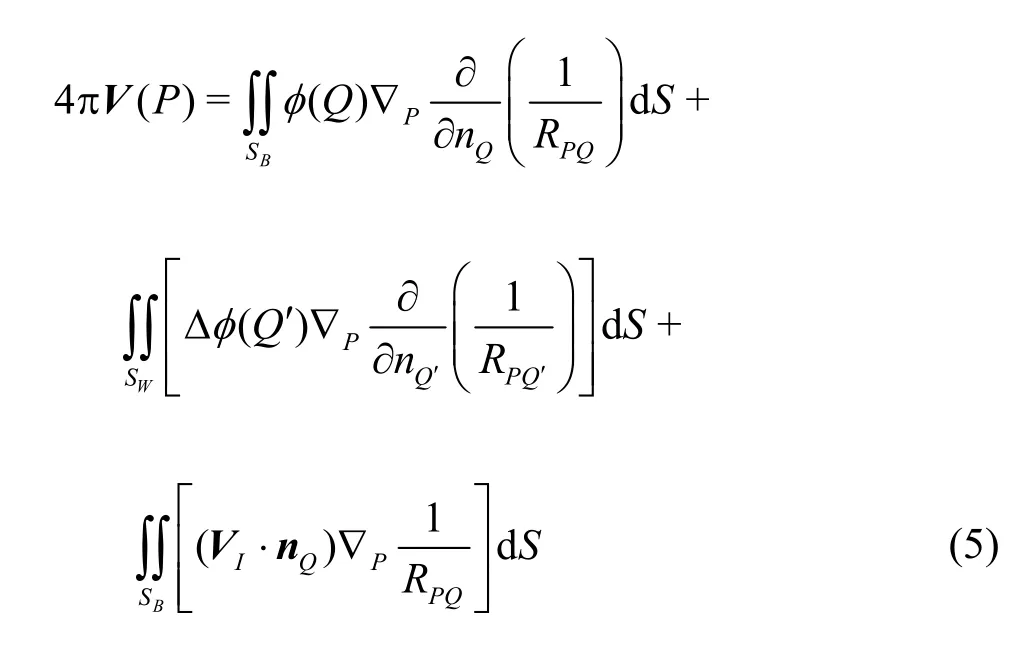
In this paper, the performance and the induced velocities of a propeller in a non-uniform inflow are evaluated by a low-order surface panel method based on the velocity potential formulation. By using Green?s 3rdIdentity, and applying the kinematic boundary condition on the non-permeable body surfaces, the following integral equation for the velocity potentials on the propeller blade and the hub surfaces holds true
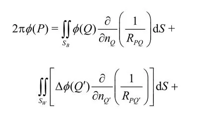
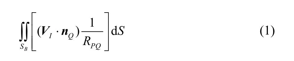
whereSB,SWdenote the blade (including the hub) surfaces and the wake surfaces, respectively,φand Δφthe velocity potential on the blade (including the hub) surfaces and its jump across the trailing vortex sheets, respectively,RPQ(oris the distance between the control pointPand the loading pointQ(orQ′),VIandnQare the inflow velocity and the unit normal vector on the body surfaces, respec- tively.

Fig.3 Comparison of calculated and measured resistances
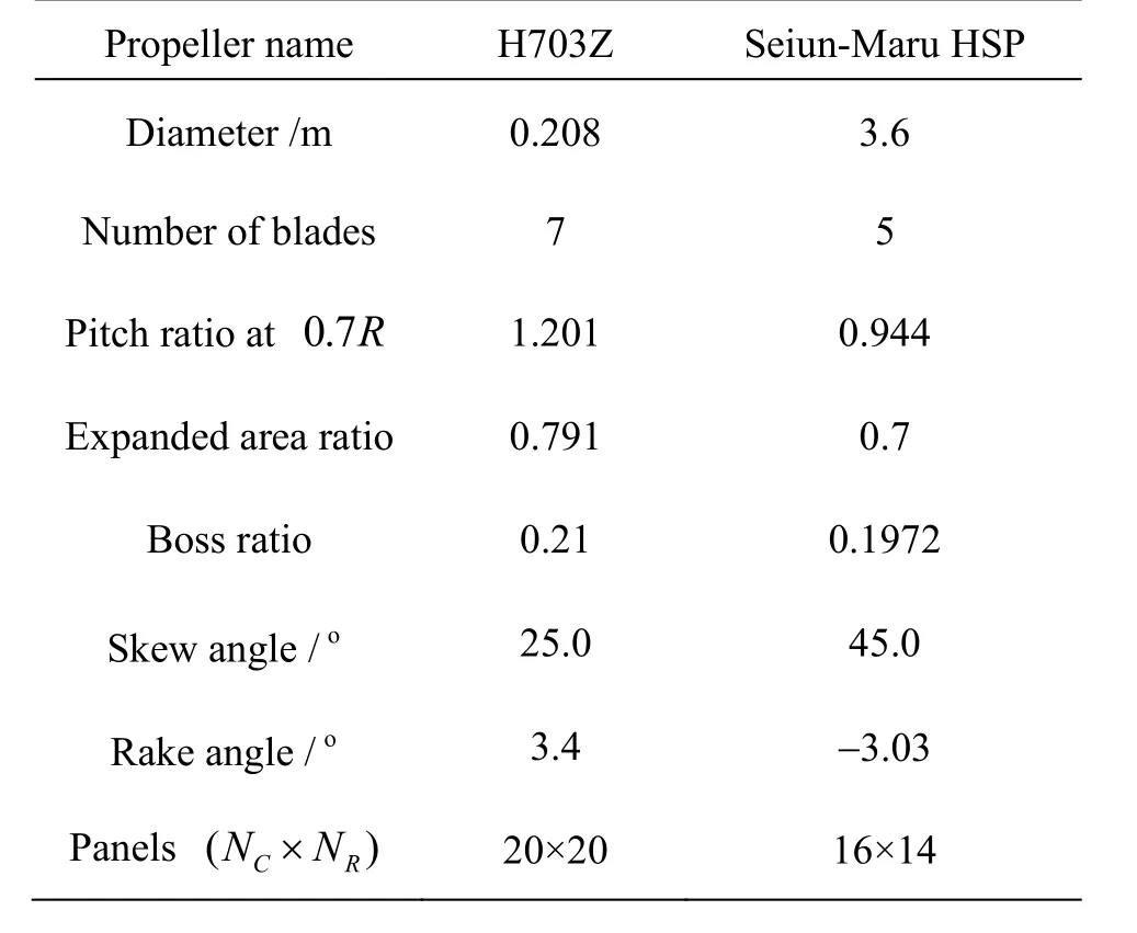
Table 2 Main parameters of calculated propellers
Computer codes are developed for simulating the steady and unsteady performances of the propeller, the latter being based on the key blade scheme and in the time domain. The blade and wake surfaces are discretized with hyperboloidal quadrilateral panels. The equal pressure Kutta condition is imposed on the blade trailing edge. The induced velocities on the blade and hub surfaces are computed by the numericaldifferentiation of the velocity potential[18]. Unsteady performance simulations start with the steady solution, and the blades rotate by 6° in each time step.
To validate the codes, the steady and unsteady performance computations are carried out, respectively, for H703Z, a seven-bladed propeller developed at the Shanghai Jiao Tong University, and the Seiun-Maru HSP[19]. The main parameters of the two propellers are listed in Table 2. The surface panels of the two propellers are shown in Fig.4.
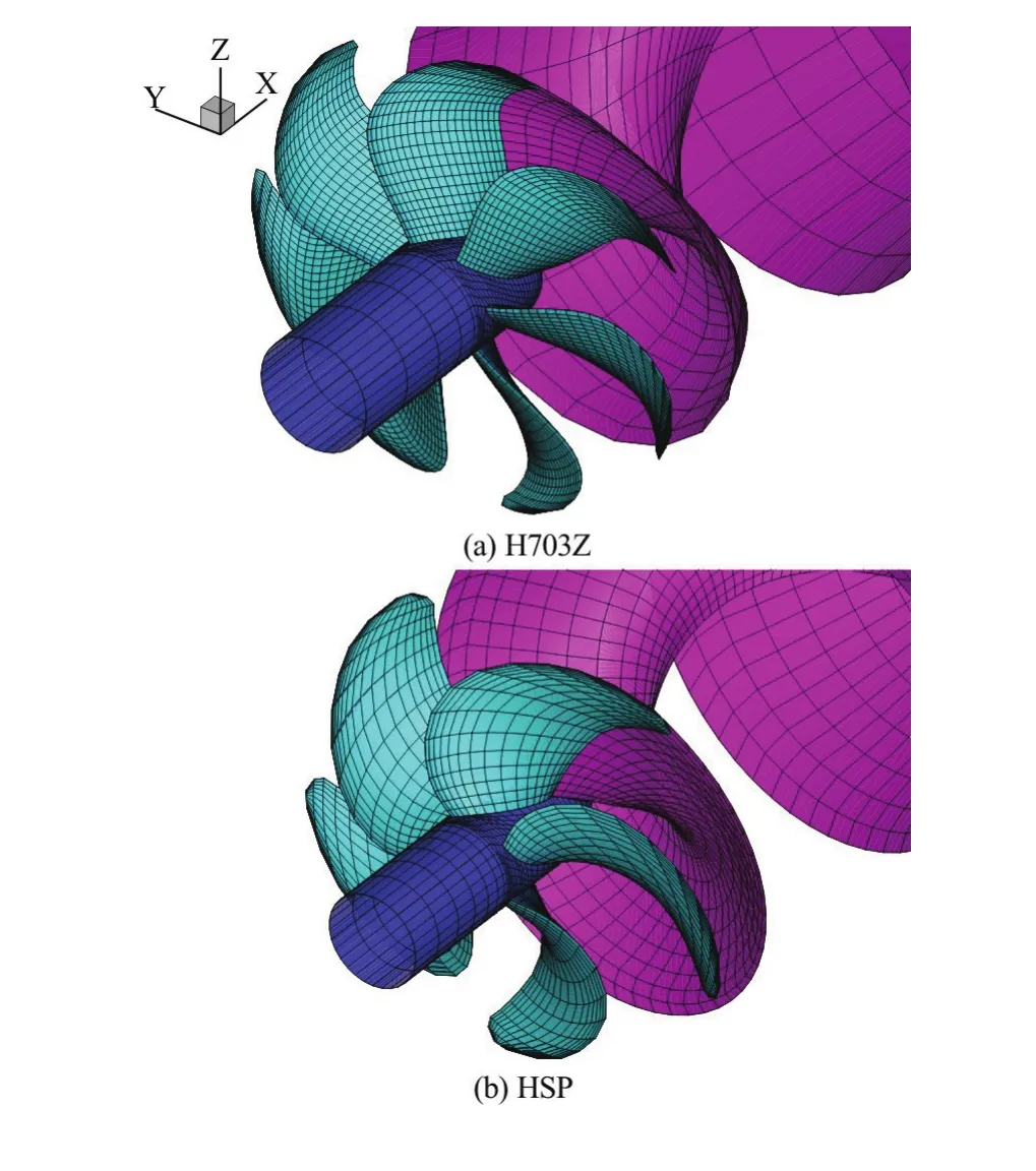
Fig.4 (Color online) Surface panel models of calculated propellers

Fig.5 Comparison of numerical and experimental open water characteristics of propeller H703Z
The surface panel and the RANS results of the open water characteristics for H703Z are plotted in Fig.5 and compared with the experimental data. It is seen that both the panel- and RANS-simulated thrusts agree satisfactorily with the experimental data, while the panel-predicted torque and efficiency are slightly lower and higher than the experimental results, respectively, as a little inferior to the RANS results.
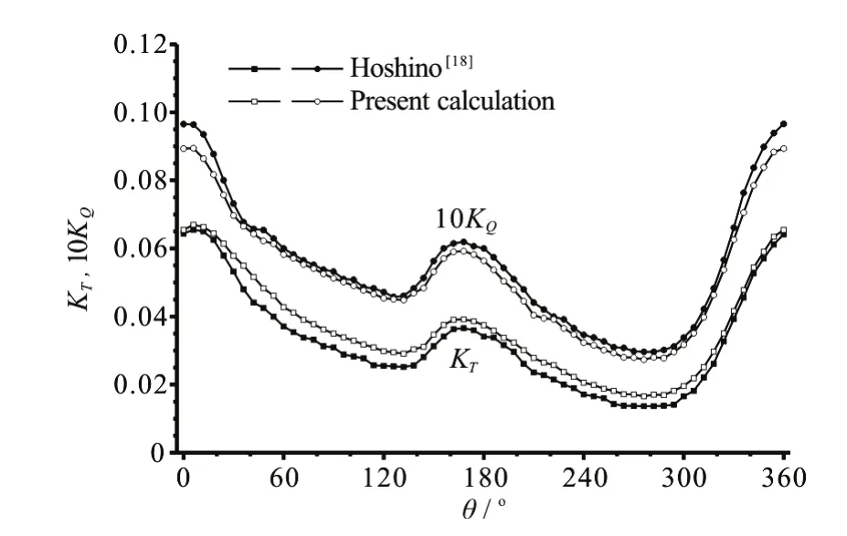
Fig.6 Variations of key-blade thrust and torque against blade angular position, Seiun-Maru HSP
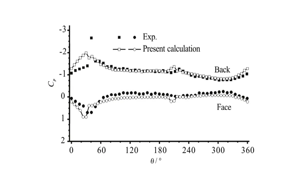
Fig.7 Variations of blade surface pressures atr/R=0.9,x/c=0.4, Seiun-Maru HSP
Figure 6 shows the variation of the thrust and the torque against the blade angular position for the key blade of the propeller Seiun-Maru HSP working in a non-uniform inflow[19]. No experimental data is available for comparison, but the present results are close to those of Hoshino, also based on a surface panel method[18]. Figure 7 shows the variations of pressure coefficientsCpat two blade surface points (0.9R, 0.4con the back and the face) during one revolution of the propeller. The present numerical predictions agree well with the measurement[19]except at angular positionsθless thano40.
Based on the above comparisons, the present surface panel methods can be considered as acceptablly accurate for the purpose of predicting the effective wake field.
1.3 Interpolation scheme of body force field
Because of the non-coincident grid nodes between the surface panel and the RANS models, the interpolation of the body force field from the potential flow to the RANS model becomes a crucial issue in the hybrid approach. An interpolation method was proposed in Ref.[15], in which the propeller force field was circumferentially averaged and linearly interpolated in the RANS simulation, and there are some inherent problems in the method, as pointed out by the authors. A conservative interpolation scheme(CIS) with high accuracy for the force field was proposed in Ref.[13], but the CIS seems slightly complicated because the potential grids need to be divided first and then reconstructed in the RANS model.
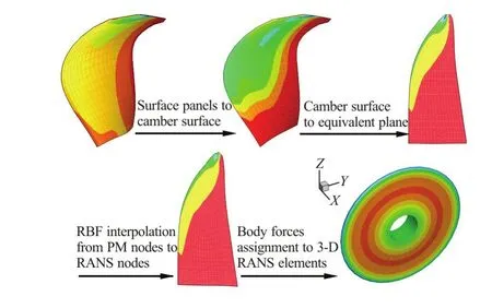
Fig.8 (Color online) Schematic diagram of the proposed interpolation scheme for a body force field
In this paper, an alternative scheme is proposed for an accurate and efficient interpolation of the body force field. It is based on interpolations through an equivalent plane. The body force zone is a volume formed by ao360 rotation of a blade around the shaft axis, as illustrated in Fig.8. The body forces are imposed on such an axisymmetric volume, and vary in both radial and axial directions. A schematic diagram of the present interpolation scheme is shown in Fig.8. Firstly, the time averaged axial and tangential forces predicted by the surface panel method are projected to corresponding elements on the camber surface (Step a in Fig.8). Since the body forces are averaged circumferentially, the force field on the camber surface can be transformed to cells on a radial plane, namely, the equivalent plane (Step b). Then the force field is interpolated to the equivalent plane in the RANS model by using RBF as the basis function (Step c). At last, the force field in the body force cell zone is determined (Step d).
The RBF interpolation is the critical point in the force field mapping. The RBF is an interpolation method for the multi-dimensional space featuring generality and flexibility. The interpolation function in the RBF can be expressed as
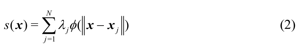
wherexjandxdenote the coordinates of the control and interpolation nodes, respectively,φis a radial basis function,jλare the coefficients of the radial basis function,Nis the number of control nodes. The following linear algebraic system needs to be solved forjλ,

whereis the known function value at thecontrol point. When the coefficients of the basis function are known, the function value at any point within the interpolation radius can be computed using Eq.(2). The Wedndland’s C2 function is adopted as the basis function, which is expressed as

The interpolation and the assignment of the body force field to the RANS simulation model are realized by creating and executing the UDF in the FLUENT.
1.4 Iteration procedure in the hybrid approach
The iteration procedure for an effective wake prediction is similar to that in Ref.[16], and is summarized here.
(1) At a specified ship speed and using an input wake field, compute the unsteady propeller performance by using the surface panel method. The propeller rotation speed needs to be adjusted so that the time-averaged thrust becomes equal to the input target thrust. Then the induced velocities are computed at specified locations where the effective wake velocities are to be evaluated.
(2) Generate the body force field by using the surface panel results obtained in Step (1) and interpolate it to the RANS simulation model.
(3) Conduct the RANS simulation for the hull under the action of the body force field, and record the hull resistance and the total velocities at the specified locations.
(4) Evaluate the effective wake field by subtracting the propeller-induced velocities obtained in Step (1) from the total velocities obtained in Step (3).
Steps (1) through (4) constitute a complete iteration loop. Once a loop is finished, the propeller rotation speed and the target thrust are, respectively, compared with those obtained in the previous loop, and the iterative computation is stopped when both quantities converge within prescribed accuracies. Otherwise, the effective wake field and the hull resistance, obtained in Steps (4) and (3), respectively, are fed to the surface panel code as the input wake field and the target thrust, and the next loop of the iterative computation starts. Prior to the first iteration, the RANS simulation of the hull flow without the propeller is conducted to obtain the initial data of theinput wake field and the target thrust required in Step (1).
By doing so, one seems to have reached at the model self-propulsion point, instead of the full-scale one, since the skin-friction correction (SFC) which accounts for the scale effect on the hull resistance has been ignored. In fact, the experimental research[20]indicates that, at a proper scale ratio, the SFC is largely cancelled by the increase in the full-scale submarine resistance, ΔR, due to the flow holes and the increased hull roughness, so that the tow forceFD, which is equal to SFC-ΔR, becomes too small to influence the propeller rotation speed. Therefore, the propeller rotation speed obtained by using the condition ofFD=0 can be considered as a good approximation of the full-scale self-propulsion point.
By definition, it is necessary to evaluate the effective wake at the propeller plane. However there is no straightforward way to do so since the propeller plane is always partially occupied by part of the rotating blades. In many studies, the effective wake was either extrapolated to the propeller plane from two planar surfaces upstream of the propeller blades[15], or directly evaluated on a surface upstream of the blade leading edges[13]. In the present paper, both alternatives are adopted by using two planar surfaces at 0.40Rand 0.30Rupstream of the propeller plane in the first alternative (named as Alter. A), or a curved surface at 0.05Rupstream of the leading edges in the second alternative (named as Alter. B), whereRis the tip radius of the propeller blades.
In the process of evaluating the effective wake, it is necessary to compute the induced velocity of the propeller. It is done by computing the gradient of the velocity potential atP, a point on the aforementioned planar or curved surfaces
where ?Pdenotes the gradient of a function at pointP. In this study, the induced velocities contributed by the sources, the 3rdterm in the right hand side of Eq.(5), are ignored since the body force field and the induced velocities are circumferentially averaged[15].
2. Verification in open water
It is necessary to check the accuracy of the present force field interpolation scheme before conducting the self-propulsion simulations. Additionally, the consistency of the induced velocities between the potential- and viscous-flow CFD simulations also needs to be ensured. To verify the interpolation accuracy and the consistency of the induced velocities, the RANS simulations of the propeller H703Z in the open water are carried out by using the present body force model. A cylindrical domain with distances of 8Dand 20D,respectively, from the inlet and the outlet to the propeller plane is used for the open water simulation. The distance between the propeller shaft and the far field boundary is 10D. The entire domain is discretized with 0.44×10⁶hexahedral cells.
Figure 9 shows the comparison of the axial body force distribution between the potential flow and interpolated RANS results. It can be seen that the body force distribution obtained by the RANS agrees well with that obtained by the potential flow except in a local area near the tip. The grids used in the surface panel method and the RANS simulation on the equivalent planes are also shown in Fig.9.
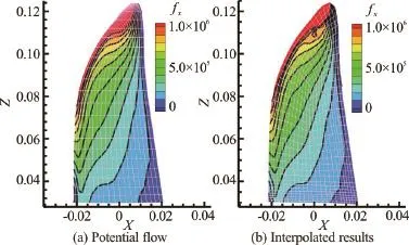
Fig.9 (Color online) Comparison of axial body force distribution

Table 3 Errors of interpolation for thrust and torque
Table 3 shows the comparison of the thrust and torque coefficients obtained by the panel method and the RANS. The errors of the RBF interpolation are less than 0.2%. The present approach has a comparable accuracy with the CIS, but the present interpolation procedure is very simple.
Figure 10 shows the dimensionless axial velocity contours near the body force zone, together with the grids in the body force zone, and the upstream locations used for the effective wake prediction. The total velocities behind the propeller zone are accelerated due to the action of the body forces.
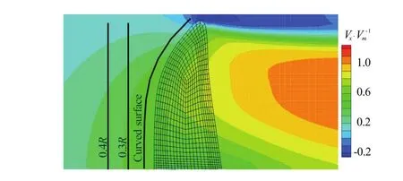
Fig.10 (Color online) Grids of body force zone and axial velocity distribution

Fig.11 Comparison of induced velocities between BEM and RANS simulations on different planes
The induced velocities at three upstream positions predicted by the potential flow and RANS simulations are compared in Fig.11. The induced velocities in the RANS simulation are obtained by subtracting the uniform inflow velocity from the total velocities. At the three positions, the axial induced velocities predicted by the panel method are slightly larger than those obtained by the RANS beyond the position of 0.4R. The radial induced velocities predicted by the two methods are close to each other on the two flat planes, but less so near the tip and the root on the curved surface. Generally speaking, the propeller performance is more sensitive to the axial inflow velocities, which makes it necessary to predict the axial induced velocities accurately. Therefore, the axial induced velocities obtained by the potential flow are corrected by taking off the mean difference in a range of 0.4R-1.0Rbetween those obtained by the panel method and the RANS. Dashed lines in Fig.11 indicate the corrected axial induced velocities obtained by the panel method, which are closer to the results of the RANS. This correction strategy is also applied in the following self-propulsion iteration. Thein the precise estimation of the effective wake.
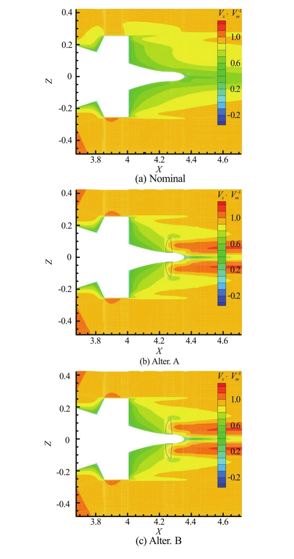
Fig.12 (Color online) Comparison of stern velocities
3. Prediction of effective wake
3.1 Simulation of self-propulsion with body forces
The surface grids and the size of the computa-tional domain in the self-propulsion simulation are the same as those of Grid 2 in the resistance computation. The submarine speed for the self-propulsion is 9.152 m/s. As noted in the aforementioned section, several iterations are needed for the self-propulsion and effective wake estimation. Table 4 and Table 5 provide the propeller thrust and torque coefficients, the propeller thrustT, the hull resistanceRand the propeller rotation speednduring each iteration using the two alternatives for the effective wake prediction. The thrust and torque coefficients obtained by the RANS are very close to those obtained by the panel method. High interpolation accuracy of the presented scheme is confirmed again in both alternatives. The results also indicate that the present hybrid approach converges quickly since three iterations are enough to reach the self-propulsion point in both alternatives.
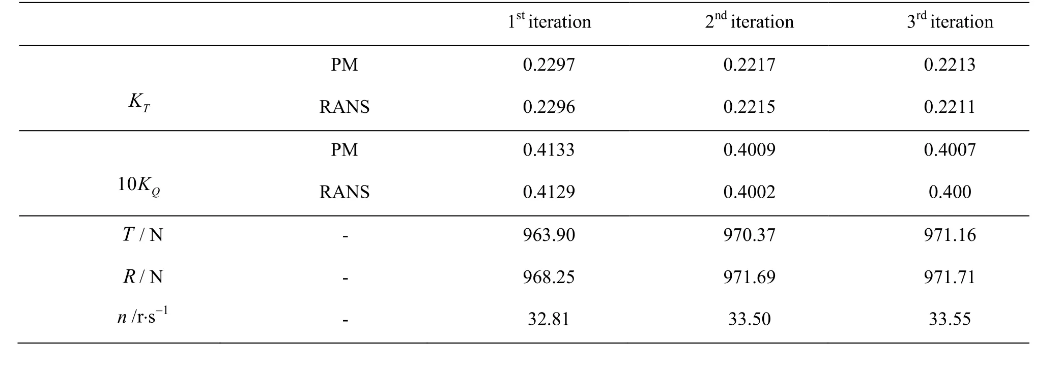
Table 4 Iterations of the hybrid approach (Alter. A)

Table 5 Iterations of hybrid approach (Alter. B)
Comparison of dimensionless axial velocities by RANS simulation is shown in Fig.12.
The flow behind the propeller zone is significantly accelerated, which makes the area of the low speed (with green color) at the stern smaller than that obtained by the nominal wake simulation. The flow velocities obtained by using Alter. A and Alter. B are nearly the same since the total body forces obtained by the RANS are close to each other.
3.2 Evaluation of effective wake distribution
The effective wake is computed by subtracting the induced velocities from the total velocities obtained by the RANS. The comparison of the nominal and effective wakes (estimated by Alter. A) is shown in Fig.13. Figure 14 shows the comparison of the effective wakes by using the two alternatives. Figure 15 shows the circumferentially averaged axial velocities of the nominal and effective wakes. The disk-averaged wake fraction is defined as
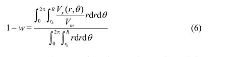
It can be seen that, due to the suction of the propeller, the effective wake distributions obtained by using the two alternatives are both larger than the nominal wake, and the low speed area of the effective wake is smaller than that of the nominal wake. The dimensionless volume mean velocities (1-w) obtained by using Alter. A and B are, respectively,0.7372 and 0.7259, which are 4.6% and 3.0% higher than the nominal one (1-w=0.7045). These results see obvious discrepancies between the nominal and effective wakes.
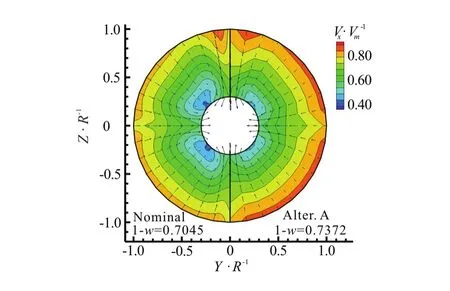
Fig.13 (Color online) Comparison of wake at propeller plane
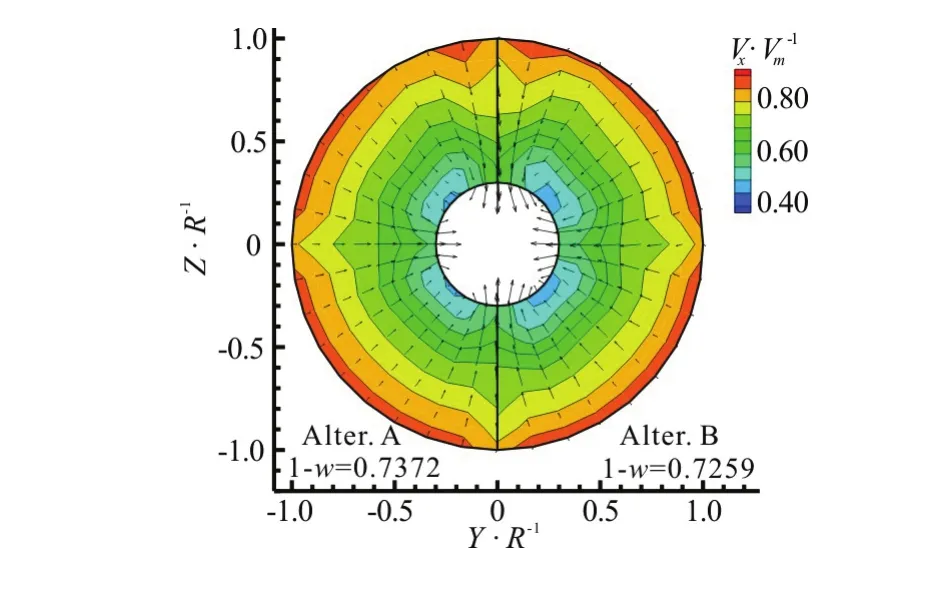
Fig.14 (Color online) Comparison of effective wake at propeller plane
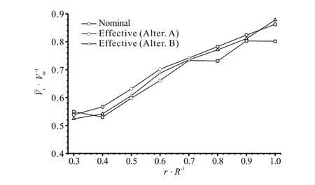
Fig.15 Comparison of circumferentially averaged axial velocities between nominal and effective wakes
The effective wake obtained by using Alter. A is 1.6% higher than that obtained by using Alter. B. This may be caused by the wake determination on the propeller plane. After all, the upstream surface is not the actual propeller plane.
3.3 Self-propulsion simulation for a real propeller geogeometry
To investigate the accuracy of the predicted effective wake, a numerical investigation is carried out by simulating the self-propulsion performance of the SUBOFF at the model scale of the real geometry of the propeller H703Z. To evaluate the effective wake fraction, the open water characteristics of the propeller are predicted by the RANS simulation. The computational domain is discretized with about 0.70×10⁶cells. The turbulence model and the spatial discretization schemes are kept the same with those in the hull resistance prediction. The resultant open water characteristics are plotted in Fig.5.
In the simulation of the self-propulsion for a real propeller geometry, the unsteady sliding mesh approach is adopted to evaluate the hull-propeller interaction. The rotating angle in each time step iso2. The surface grids and the domain size are the same as those used in Grid 2. The total number of cells in the domain is 8.27×10⁶. The grids on the hull and blade surfaces are shown in Fig.16. The model speed is again 9.152 m/s.
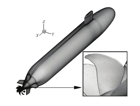
Fig.16 Grids of self-propulsion simulation for SUBOFF with a propeller
Comparisons of the propeller rotation speed and the wake fraction between the hybrid approach and the sliding mesh simulation are shown in Table 6. The propeller revolution speeds and the wake fractions are close to each other by using the two approaches. The hull resistance estimated by the sliding mesh model is 3% higher than those obtained by using the hybrid approach. It should be noted that the wake fractions in Table 6 are calculated by using the thrust identity method, which is different from Eq.(6) used in Figs.13, 14. Table 7 shows the computation time of the two approaches by using the computer of Intel Xeon, 8 cores, 2.13 GHz. With the hybrid approach, the computation time is saved as compared to the sliding mesh simulation.
Viewing from the entire procedure of the effective wake prediction, the hybrid approach is lesstime-consuming owing to the less grids and the steady simulation. The hybrid approach can be used to predict not only the effective wake fraction, but also the effective wake field on the propeller disk. The latter is of significance for designing the wakeadapted propellers.
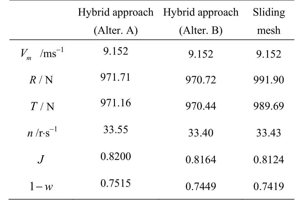
Table 6 Comparison of self-propulsion results
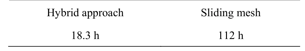
Table 7 Comparison of computation time
4. Conclusions
A hybrid approach coupled with a surface panel method for the propeller and a RANS model for the hull with the propeller body forces are developed for predicting the self-propulsion performance and the effective wake field of underwater vehicles. An RBF based interpolation method is proposed for the force fields mapping from the potential flow to the RANS simulation. The effective wake field is estimated by using two alternatives: the extrapolation from the upstream planes to the propeller plane, and the direct evaluation in a curved surface upstream of the blade leading edges. Numerical simulations are carried out for the fully appended SUBOFF submarine model by using the hybrid approach, and the results are numerically verified by the RANS simulation for a real propeller geometry and the sliding mesh model.
The RBF based interpolation method enjoys a high accuracy in the force field mapping. The force field obtained by the RANS is consistent with that obtained by the potential flow method. The interpolation errors in the thrust and the torque are less than 0.5%.
The disk-averaged axial velocity obtained by the extrapolation from the upstream planes is 1.6% higher than that obtained by the direct computation in the curved surface upstream of the blade leading edges, and the two results are, respectively, 4.6% and 3% higher than the nominal axial velocity. Due to the propeller action, the effective wake field is significantly different from the nominal one.
The wake fractions and the propeller rotation speeds are close to each other as obtained by the hybrid approach and the sliding mesh simulation.
[1] Park S., Oh G., Rhee S. H. et al. Full scale wake prediction of an energy saving device by using computational fluid dynamics [J].Ocean Engineering, 2015, 101: 254-263.
[2] Meng Q. J., Wan D. C. Numerical simulations of viscous flow around the obliquely towed KVLCC2M model in deep and shallow water [J].Journal of Hydrodynamics, 2016, 28(3): 506-518.
[3] Noblesse F., Zhang C., He J. et al. Observations and computations of narrow Kelvin ship wakes [J].Journal of Ocean Engineering and Science, 2016, 1: 52-65.
[4] Wang B. L., Guo X. Y., Liu H. et al. Numerical simulations of wake signatures around high-speed ships [J].Journal of Hydrodynamics, 2014, 26(6): 986-989.
[5] The Propulsion Committee. Final report and recommendations to the 27th ITTC [C].The 27th International Towing Tank Conference. Copenhagen, Denmark, 2014.
[6] Wu Z. H., Chen Z. G., Dai Y. Numerical prediction of self-propulsion with a body-force propeller model [J].Journal of Shanghai Jiaotong University, 2013, 47(6): 943-949(in Chinese).
[7] Fu H. P., Michael T. J., Carrica P. M. Computation on self-propulsion at ship point based on a body-force propeller [J].Journal of Ship Mechanics, 2015, 19(7): 791-796(in Chinese).
[8] Tahara Y., Wilson R. V., Carrica P. M. et al. RANS simulation of a container ship using a single-phase level-set method with overset grids and the prognosis for extension to a self-propulsion simulator [J].Journal of Marine Science and Technology, 2006, 11(4): 209-228.
[9] Sánchez-Caja A., Martio J., Saisto I. et al. On the enhancement of coupling potential flow models to RANS solvers for the prediction of propeller effective wakes [J].Journal of Marine Science and Technology, 2015, 20(1): 104-117.
[10] Sakamoto N., Kawanami Y., Uto S. et al. Estimation of resistance and self-propulsion characteristics for low L/B twin-skeg container ship by a high-fidelity RANS solver [J].Journal of Ship Research, 2013, 57(1): 24-41.
[11] Zheng Y., Chen Z. G., Dai Y. Numerical prediction of propulsive performance with an iterative body-force propeller model [J].Journal of Shanghai Jiaotong University, 2015, 49(2): 269-274(in Chinese).
[12] Yang C. L., Zhu R. C., Miao G. P. et al. A method of viscous CFD/potential flow coupling iterative solution for ship/propeller interaction [J].Journal of Shanghai Jiaotong University, 2014, 48(12): 1795-1801(in Chinese).
[13] Tian Y., Jeon C. H., Kinnas S. A. On the accurate calculation of effective wake/application to ducted propellers [J].Journal of Ship Research, 2014, 58(2): 70-82.
[14] Villa D., Gaggero S., Brizzolara S. Ship self propulsion with different CFD methods: From actuator disk to viscous inviscid unsteady coupled solvers [C].The10th International Conference on Hydrodynamics. St. Petersburg, Russia, 2012.
[15] Starke A. R., Bosschers J. Analysis of scale effects in ship powering performance using a hybrid RANS-BEM approach [C].The 29th Symposium on Naval Hydrodynamics.Gothenburg, Sweden, 2012.
[16] Rijpkema D., Starke B., Bosschers J. Numerical simulation of propeller-hull interaction and determination of the effective wake field using a hybrid RANS-BEM approach [C].The 3rd International Symposium on Marin Propulsors. Tasmania, Australia, 2013, 421-429.
[17] Bull P. The validation of CFD predictions of nominal wake for the SUBOFF fully appended geometry [C].The 21st Symposium on Naval Hydrodynamics. Trondheim, Norway, 1996, 1061-1076.
[18] Hoshino T. Hydrodynamic analysis of propellers in unsteady flow using a surface panel method [J].Journal of the Society of Naval Architects of Japan, 1993, 174: 71-87.
[19] Ukon Y., Kudo T. et al. Measurement of pressure distribution on a full scale propeller-measurement on a highly skewed propeller [J].Journal of the Society of Naval Architects of Japan, 1990, 170: 1-14.
[20] Zhu A. J., Ying L. M., Hu K. et al. A discussion on the self-propulsion model test method for underwater vessel [J].Journal of Ship Mechanics, 2012, 16(4): 383-389(in Chinese).
(Received July 13, 2016, Revised April 6, 2017)
* Project supported by the National Basic Research Development Program of China (973 Program, Grant No. 613134).
Biography:Zhi-qiang Rao (1986-), Male, Ph. D. Candidate
Chen-jun Yang,
E-mail: cjyang@sjtu.edu.cn
猜你喜歡
中國圖書評論(2022年12期)2022-12-26 09:32:46
關(guān)東學刊(2022年5期)2022-10-21 02:28:42
小學生學習指導(中年級)(2021年11期)2021-11-30 02:17:50
延河(下半月)(2021年7期)2021-08-10 02:40:16
江蘇安全生產(chǎn)(2020年3期)2020-04-21 05:44:12
海峽姐妹(2019年4期)2019-06-18 10:39:00
寶藏(2018年12期)2019-01-29 01:50:50
Acta Mathematica Scientia(English Series)(2018年3期)2018-07-23 08:41:42
Journal of Meteorological Research(2015年5期)2015-11-21 11:23:19
中華奇石(2014年12期)2014-07-09 18:30:22

- 水動力學研究與進展 B輯的其它文章
- ICHD’ 2018 The 13th International Conference on Hydrodynamics First Announcement
- Cavitation erosion in bloods*
- A GPU accelerated finite volume coastal ocean model*
- Mixing features in an electromagnetic rectangular micromixer for electrolyte solutions*
- A numerical study of violent sloshing problems with modified MPS method*
- Numerical investigation of entropy generation and heat transfer of pulsating flow in a horizontal channel with an open cavity*