
Mixing features in an electromagnetic rectangular micromixer for electrolyte solutions*
2017-09-15 13:55:51WenKim
水動力學(xué)研究與進展 B輯 2017年4期
M. M. Wen, C. N. Kim
1.Department of Mechanical Engineering, Graduate School, Kyung Hee University, Yong-in, Korea, E-mail: wenmeimei0715@163.com
2.Department of Mechanical Engineering, College of Engineering, Kyung Hee University,Yong-in, Korea
Mixing features in an electromagnetic rectangular micromixer for electrolyte solutions*
M. M. Wen1, C. N. Kim2
1.Department of Mechanical Engineering, Graduate School, Kyung Hee University, Yong-in, Korea, E-mail: wenmeimei0715@163.com
2.Department of Mechanical Engineering, College of Engineering, Kyung Hee University,Yong-in, Korea
In this study, a new magnetohydrodynamic (MHD) mixer for electrolyte solutions with pumping function is reported, and the mixing performance of the device for two different electrolyte solutions is numerically examined in a uniform magnetic field. Application of different potentials to different electrodes allows the current to be induced. The combination of the induced current and magnetic field yields Lorentz force, resulting in the fluid motion. The numerical simulation for the flows in the device is carried out with commercial software CFX. The validity of CFX code for the present numerical model is presented. The mixing performance of the fluids is investigated in many different cases with different combinations of input voltage of the electrode. This study shows that the mixing performance can be enhanced by applying spatially alternating positive and negative voltages to the electrodes. The present simulation results show that with a magnetic field intensity lower than 0.5 T, a voltage difference smaller than 2.0 V, and an electric conductivity of electrolyte solution of 1.5 S/m the pumping capabilities ranging 1.6×10⁻⁷-3.6×10⁻⁶kg/s and the mixing indexes higher than 0.90 can be obtained with sophisticated designs of the micromixer.
Mixer, electrolyte solution, Lorentz force, CFX
Introduction
Over the last decade, microfluidic devices have been widely used in various fields, such as biotechnology, biomedicine, chemistry, food and environment technology[1]. In these applications, it is often necessary to pump the fluids from one part of the device to another part. Meanwhile, the efficient mixing of the fluids is also required. The characteristic length of the microchannel is usually very small, and the time required for mixing is too long with low diffusivity. In addition, the Reynolds number of liquid flows in such microchannels is small, and turbulence is not available[2]. Hence, more efficient microdevice is needed to accelerate the mixing process. Magnetohydrodynamic (MHD) flow offers a relatively convenient way for pumping and mixing.
Recently, a number of researchers have constructed different kinds of micropumps with the MHD effect. Lim and Choi[3]fabricated an MHD micropump with side-walled electrodes, and the performance of the device was investigated by numerical simulation and experiment. Jang and Lee[4]constructed a micropump in which the Lorentz force was utilized as the pumping source. The proposed micropump had many advantages over other types of micropumps, such as simple fabrication process and bidirectional pumping ability. Lemoff and Lee[5]presented an AC MHD micropump which produced a continuous flow (not pulsatile) and was compatible with solutions containing biological samples. The design of the AC MHD micropump enabled multiple, independently-controlled pumps to be integrated on a single chip. Zhong et al.[6]designed a micropump with low temperature, co-fired ceramic tapes (LTCC). The LTCC technology facilitated the integration of electrodes, conductors and hydraulic paths, thus providing a convenient platform for the construction of the device. They demonstrated that the suggested micro-pump was able to drive liquids such as mercury, saline solution and deionized water in minute conduits.
The Lorentz force can be used not only for the purpose of pumping fluids, but also for mixing. In recent years, many researchers have proposed a variety of MHD micromixers, and analyzed their performances, using theoretical and experimental methods. Yi et al.[7]presented an MHD mixer, and examined the mixing performance theoretically and experimentally. The experimental observations were in good agreement with theoretical predictions. Qian et al.[8]described an MHD mixer in which the Lorentz force was used to control fluid flow in microfluidic networks. By prescribing the potentials of the electrode pairs, the fluid flow could be controlled in a programmable way. In the work of Affanni and Chiorboli[9], an MHD micromixer was analytically modeled and experimentally tested. They showed that the mixer could achieve a very high mixing efficiency within a short period of time.
Meanwhile, the numerical solution method based on computational fluid dynamics has been widely used for the analysis of MHD mixers. Lee et al.[10]presented an MHD micromixer with a simple structure. Commercial CFD-ACE code was utilized to estimate the mixing efficiency of the device. It was confirmed that the proposed micromixer was able to achieve high mixing efficiency. In the study of La et al.[11], complicated fluid motions in the mixer were created by the Lorentz force that could have various magnitudes and directions. Here, three-dimensional CFD simulations under steady-state condition were carried out to examine the mixing performance of the device.
The microdevice in La’s work[11]can serve as a mixer as well as a pump, but a pair of side-walled electrodes is used for pumping and many pairs of bottom-walled electrodes are employed for mixing. However, in the present study a new MHD microdevice is devised for electrolyte solutions with mixing and pumping functions. Here, the arrangement of the electrodes allows any electrode to induce current flows that can be used for simultaneous pumping and mixing, which is quite different from those of Refs.[10,11].
In view of the previous works, several studies[7-11]have been performed for MHD mixers, but only few numerical works[10,11]on MHD mixers can be found. Yi et al.[7]and Qian et al.[8]theoretically and experimentally investigated the mixing performance of rectangular MHD mixers, where the mixers had the mixing function only. Lee et al.[10]presented an MHD micromixer with a chaotic flow, in which the electrodes were positioned on the top wall of the microchannel, which were used for mixing only. But, in the present study, the electrodes positioned on the top and bottom walls of the microchannel are used for simultaneous mixing and pumping, thus the time (and/or the length of the device) for well mixing is shortened. In this study, the effect of arrangement of electrode voltage on the mixing performance of the device is investigated, and the mixing index is defined to quantify the mixing quality, which is not mentioned in the work of Lee et al.[10].
In this study, the application of different electric potentials to different electrodes can create a Lorentzforce that directs the liquid to move along a desired path for pumping without a need of separate pumps, and induces the fluid circulation for mixing. Since there are no moving mechanical parts, the mixer design is appropriate for various microfluidic applications. With appropriate potential differences across the wall-electrodes, the resulting Lorentz forces can be used for simultaneous pumping and mixing. In other words, the proposed design of micromixer has design flexibility in terms of the degree of the mixing and pumping, where the change in the direction of the magnetic field induces the change in the ratio of the Lorentz force for mixing to that for pumping. In this work, we have described just simple situations where Lorentz force is used to pump and mix the electrolyte solutions in a rectangular conduit. Furthermore, the effect of variables on mixing performance is numerically examined in many different cases with different combinations of the electrode voltage. The detailed information of current density, velocity distribution, and mass fraction of two miscible fluids, together with the value of mixing index, is obtained.
1. Problem formulation
1.1 Geometry, magnetic field and materials
Phosphate buffered saline (PBS) solution is a water-based salt solution, which is usually used as a medium for the fixation of protein in biological research. In the present study, PBS is used as the working fluid, whose properties are shown in Table 1.
In the current study, two cases (Case 1 and Case 2) with different patterns in combinations of input voltage of the electrode are examined, as shown in Table 2. In Case 2, six subcases (Case 2-1, Case 2-2, Case 2-3, Case 2-4, Case 2-5 and Case 2-6) with different values (absolute values) of the applied electrode voltage are considered. The duct geometries in Case 1 and Case 2 are the same, as depicted in Fig.1. In this study, the two fluids are referred to as Fluid A and Fluid B, respectively. Here, the aspect ratio of the duct is 0.2 (width of 1 mm, height of 5 mm), which is obtained from the consideration that the proposed aspect ratio allows good mixing and does not create a meaningful difference in the mass flow rate of Fluid A and Fluid B based on the given distance between the inlet and the leading edge of the first electrode. In Fig.1(a), six electrodes are positioned on the walls ofthe conduit. Three electrodes are on the left vertical wall, denoted by L1, L2and L3, respectively, the other three are on the right vertical wall, denoted by R1, R2and R3, respectively. The size of each electrode is 1 mm×1 mm. As shown in Fig.1(b), the horizontal distance between any two adjacent electrodes (i.e., the horizontal distance between R1and R2) is 1 mm. A uniform magnetic field (B) is applied in all cases,with0.3 Tesla.
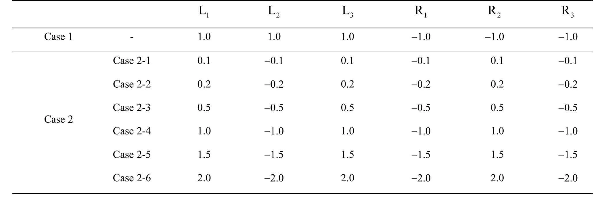
Table 2 Input voltages of the electrodes in different cases (V)
The combination of the induced current (J) and magnetic field (B) yields Lorentz force (F,F=J×B), , resulting in the fluid motions for simultaneous pumping and mixing without the need of mechanical pumps or stirrers. The Lorentz force is the only driving force for the fluid flow in the system. Figure 2 shows the schematic diagrams of the induced current and the corresponding Lorentz force in Case 1. In Fig.2(a), thez-directional current (Jz) combines with thex-directional component of magnetic field (Bx), yielding they-directional Lorentz forcewhich is used for mixing. Meanwhile, as depicted in Fig.2(b), with the combination of thez-directional current (Jz) and the negativeydirectional component of magnetic field (By), thex-directional Lorentz force (Fx=JzBy) used for pumping is induced. IfFyis too large, the effect of mixing will be too strong. IfFxis too large, the effect of pumping will be strong. Therefore, the magnitude of the two forces should be well allocated.
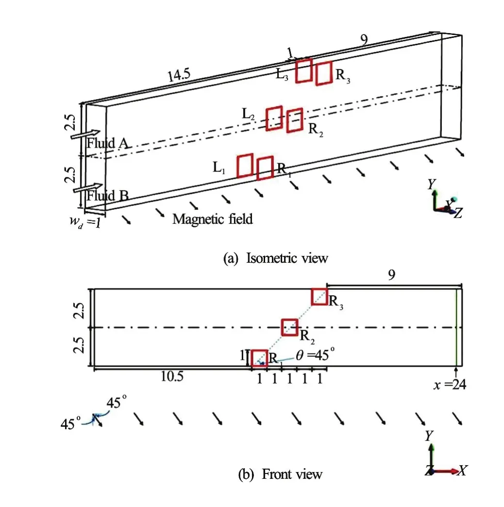
Fig.1 (Color online) Geometry of the duct in different views, and illustration of the position (in green) for displaying the mixing performance, wherewdis the width of th duct (mm)
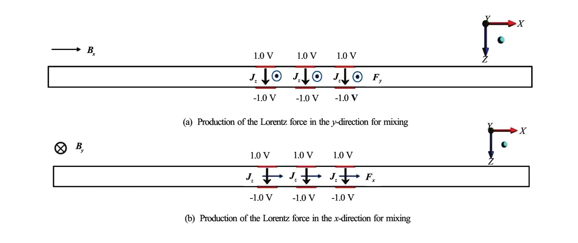
Fig.2 (Color online) Schematic diagrams of the induced current (J) and the corresponding Lorentz force (F) in Case 1, top view

Fig.3 (Color online) Schematic diagrams of the induced current (J) and the corresponding Lorentz force (F) in Case 2-4, top view
The schematic diagrams of the induced current and the corresponding Lorentz force in Case 2-4 is shown in Fig.3. Since the spatially alternating arrangement of positive and negative potentials on the electrodes is used in Case 2-4, the direction of the induced current alternates, as presented in Fig.3. Consequently, the corresponding Lorentz force’s direction also alternates.
With the same magnitude (absolute value) of thex-directional andy-directional components of the magnetic field intensity, the magnitude (absolute value) of the inducedx-directional andy-directional components of Lorentz force are expected to be the same. Thus, the above-mentioned Lorentz force will enhance the velocity in the direction with an angle of 45o(the direction between thex- andy-direction) in Case 1, or will increase the complexity of the flow in Case 2, with the arrangement of the electrodes along the line ofθ=45o(see Fig.1(b)) with respect to thex-direction, as long as other effects on the direction of the flow are neglected.
1.2 Governing equations
A steady-state, incompressible, constant-property, laminar flow of an electrically conducting fluid in a uniform magnetic field is considered. The system of governing equations for electrically-conducting fluid in a magnetic field includes the Navier-Stokes equation with Lorentz force, conservation of mass, conservation of charge and Ohm’s law, which can be written as follows:
Conservation of mass

Equation of motion

Conservation of the charge
Ohm’s law
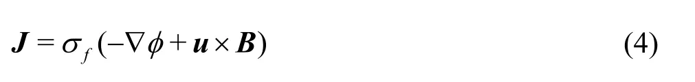
whereu,ρ,p,μ,σf,J,Bandφare fluid velocity vector, fluid density, pressure, dynamic viscosity of the fluid, electrical conductivity of the fluid, current density vector, magnetic field intensity and electric potential, respectively.
Substituting Eq.(4) into Eq.(3) gives the following equation for the electric potential, where the electrical potential has an elliptic behavior with a source term of the electromotive forces
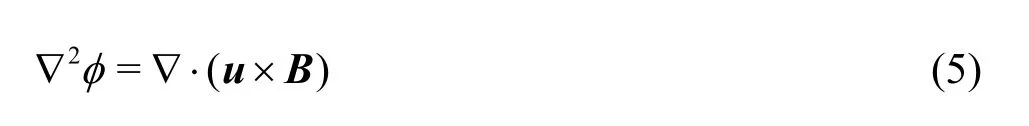
Equations (1), (2) and (5) are to be solved for velocity, pressure, and electric potential of the flow. The concentration distribution inside the whole duct can be described by the following convective-diffusion equation

whereCis the concentration of Fluid A, andDis the binary diffusion coefficient.
With an appropriate nondimensionalization, nondimensionalized variables (marked by*) in the below can be obtained as:
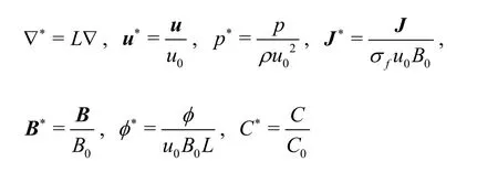
whereL,u0,B0,C0are the characteristic length, characteristic velocity, characteristic magnetic field strength and characteristic concentration.
Then, the nondimensionalized equations corresponding to the system of Eqs.(1)-(4) can be written as follows:
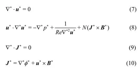
where the term “Re” and “N” means the Reynolds number and Interaction parameter, respectively.
The Reynolds number (Re) is the ratio of the inertial effect to viscous effect, as shown in the following equation
whereu0is the characteristic velocity (average axial velocity) of the fluids, andLis the characteristic length (hydraulic diameter, 2 height·width/(height+ width)) of the channel. In this system, the value ofReis around 16, which indicates that the flow in the microchannel is laminar.
The Interaction parameter (N) can be expressed as the ratio of magnetic force to inertia force, while the Hartmann number (Ha) can be regarded as the ratio of magnetic force to viscous force, as shown in the below:
The value ofNandHain the present work is 7.7×10⁻⁵and 0.035, respectively, indicating that the magnetic force is not very large compared with the inertia or viscous force.
Also, the equations corresponding to Eqs.(5) and (6) can be written as follows:
where the term “Pem” is the Peclet number for mass transfer.
The Peclet number for mass transfer (Pem) is the ratio of the characteristic time of diffusive effect to the characteristic time of inertial effect, which is defined by
In this study, the value of binary diffusion coefficient isD=10-10m2/s[12]. Then, the typical value ofPemis around 7.1×10⁴, reinforcing that thetypical diffusion time scale is much larger than the convective time scale. As a consequence, the convective transport dominates diffusive transport when the Peclet number is large, and the dispersion of the fluids in the flow field can be greatly enhanced by promoting the convective transport. Therefore, an electromagnetic rectangular micromixer is designed to enhance the convection to improve the mixing in microchannel in the present study.
1.3 Boundary conditions
No slip condition is applied at the liquid-wall interface. At the inlet and outlet of the duct, the pressure is prescribed to be zero, and there is no change in the variables (except for the pressure) along the main flow direction. It is considered that there is no normal current at the inlet, outlet, and liquid-wall interface (except at the electrodes), which yields the insulating boundary condition for the electricity?φ/?n=0, wherenis the unit vector outer normal to the side wall.
The boundary condition for the concentrations (C) at the side wall is ?C/?n=0, which follows from the assumption that the wall boundary prohibits the diffusion in the fluids. In this study, two different electrolyte solutions are referred to as Fluid A and Fluid B, whose concentrations before entering the inlet are 1 and 0, respectively.
1.4 Numerical method
After a series of grid independence tests, a structured grid system with around 62 720 grids is chosen in the present study, which is used for all the cases. To solve the discretized equations, the Multigrid-accelerated Incomplete Lower Upper Factorization technique[13,14]is used. Under-relaxation is utilized in the iteration procedure for the solution of the coupled governing equations. The second-order upwind scheme is used to discretize the convection terms and the central difference scheme is used for the diffusion terms.
2. Validity of CFX code
2.1 Ohm’s law without electromotive force
In this section, the reliability of CFX code used in the present study is validated for a problem of Ohm’s law without electromotive force. A two-dimensional rectangular solid is considered, whose conductivity (σs) is 1.5 S/m, as depicted in Fig.4(a). The aspect ratio of the rectangular plane is 4.0 (width of 1 m, height of 0.25 m). The four sides of the plane are denoted by H1, H2, H3, H4, respectively. Given that the top and bottom sides (H3and H4) are electrically insulated, and the electrical potential imposed on H1, H2are 1.0 V, -1.0 V, respectively. Then, the current is to be induced in the plane by the gradient of the electrical potential. The current distribution obtained from the CFX simulation is shown in Fig.4(b), and the magnitude of the current is 3 A/m2in all the computational domain. Also, simple mathematical calculation based on Ohm’s lawyields the magnitude of the current to be 3 A/m2, demonstrating the validity of the CFX code in the calculation of Ohm’s law without electromotive force.
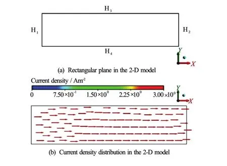
Fig.4 (Color online) Schematic diagrams of the plane and current density
2.2 Velocity profile with Ohm’s law with electromotive force
The accuracy and reliability of CFX code for the flow of electrically conducting fluids under a uniform magnetic field is validated against the analytical solution of Walker[16]and the numerical result of Mistrangelo[17]. The fully developed MHD flow in a duct with rectangular cross-section is analyzed. The duct geometry and the applied magnetic field used for the simulation are shown in Fig.5(a). The fluid flows in thex-direction, and a uniform magnetic field is applied parallel to they-axis. In Fig.5(a), the aspect ratio of the cross-section in they-zplane is 4.0. All the walls have the same electric conductivity and the conductance parameter (c), which is defined to be, wheretis the thickness of the duct wall. In the validation,cis assumed to be 0.1 and the Hartmann number is 1 000.
The comparison of the axial velocity among the present simulation result, the analytical solution and Mistrangelo’s numerical result in the midx-zand midx-yplanes is shown in Figs.5(b) and 5(c), and it demonstrates a good agreement. Up to Hartmann number of 1 000, the reliability of CFX code in theprediction of the flow features in MHD flows is validated[17]. The typical value of Hartmann number in the proposed micromixer is even smaller than 1, therefore, CFX code can be safely applied to the study of the flow in the current micromixer.
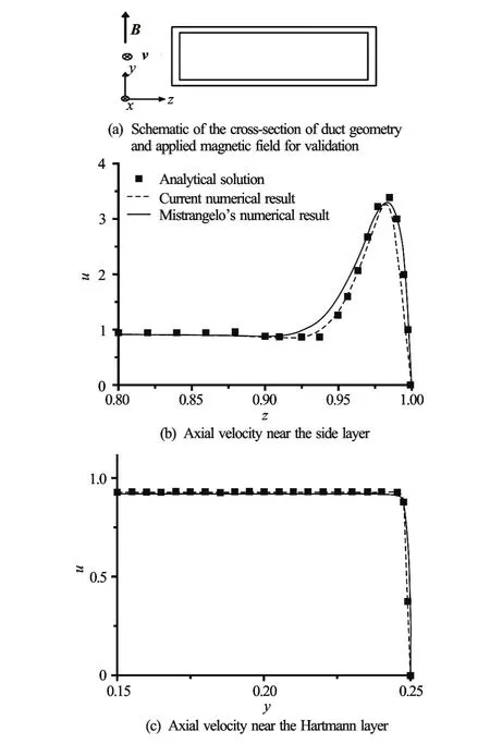
Fig.5 Comparison of the axial velocities of the analytical solution, the Mistrangelo’s numerical result and the present numerical result
3. Results and discussions
3.1 Flow features in Case 1
Figure 6(a) shows the three-dimensional velocity streamlines in Case 1 (Ha=0.035,Re=11.6). As presented, the fluids are sucked at the inlet, then form one counter-clockwise circulation in the fluid region above R1and R2, and another clockwise circulation in the fluid region below R2and R3, and finally, flow out at the outlet.
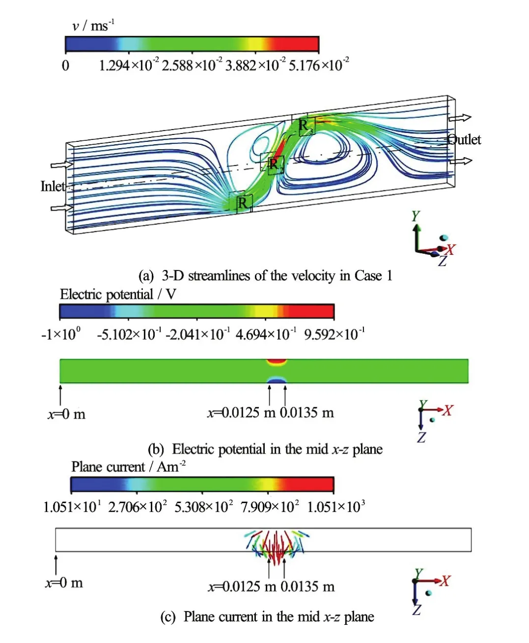
Fig.6 (Color online) Three-dimensional streamlines of the velocity, distributions of the electric potential and plane current in the midx-zplane (y=0.0025m)in Case 1
The distribution of the electric potential in the midx-zplane (y=0.0025 m , see Fig.1) in Case 1 is obtained, as depicted in Fig.6(b). It is to be reminded that the boundary condition for the electric potential is that the walls (except the electrodes), inlet and outlet are electrically insulated. The electric potential in the upper side (parallel to thex-direction in Fig.6(b)) where L2is located (fromx=0.0125 m to 0.0135 m, see Fig.1(b)) is much higher than that in the lower side where R2is located (see Fig.1(b)), causing the current to flow approximately in thezdirection, as displayed in Fig.6(c). Thus, the Lorentz force havingx-directional andy-directional components is induced. The Lorentz force distribution in the midx-yplane (z=0.0005 m , see Fig.1) is presented in Fig.7(a), where the force vectors are headed in the direction ofo45 with respect to thex-axis. Figure 7(b) shows the plane velocity in the midx-yplane, where an anticlockwise fluid circulation (in the fluid region above R1and R2) and a clockwise fluid circulation (in the fluid region below R2and R3) are observed, which are induced by the abovementioned Lorentz force. Figure 7(c) shows the pressure distribution in the same plane, caused by the above-described fluid motions. Since the pressure in the fluid region near R3is higher and that near R1is lower, the pressure force is, in part, balanced by theLorentz force. It is to be noted that the fluid flow depicted in Fig.7(b) is the outcome of distributions of the Lorentz force and the pressure.
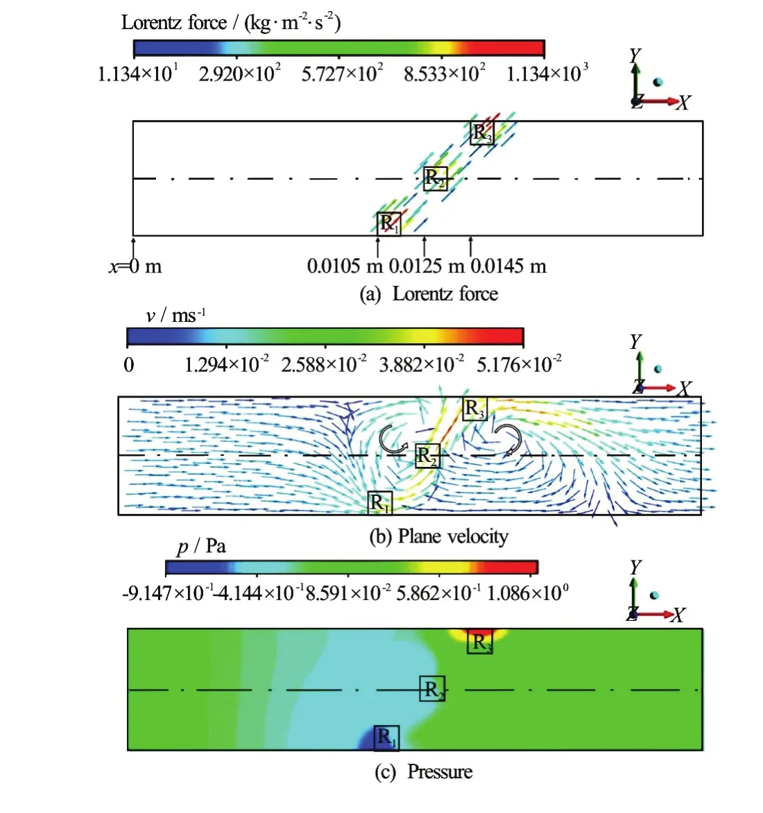
Fig.7 (Color online) Distributions of the Lorentz force, velocity and pressure in the midx-yplane (z= 0.0005 m) in Case 1
3.2 Flow features in Case 2
In this section, the investigation of mixing performance is carried out in six subcases (Case 2-1, Case 2-2, Case 2-3, Case 2-4, Case 2-5 and Case 2-6) with different values (absolute values) of the input voltage. Since the fluid motions in other subcases (except Case 2-4) are similar to that in Case 2-4, the detailed description in Case 2-4 will be shown, but those in other subcases are not to be displayed.
Figure 8(a) depicts the three-dimensional velocity streamlines in Case 2-4 (Ha=0.035,Re=15.2). Here, four fluid circulations are formed in the fluid region near the electrodes, and higher velocity is observed in the fluid region near R2.
Figure 8(b) shows the electric potential distribution in the midx-zplane (y=0.0025 m, see Fig.1) in Case 2-4. The electric potential is much higher in the lower side (parallel to thex-direction in Fig.8(b)) where R2is located (fromx=0.0125 m to 0.0135 m, see Fig.1(b)). Considering the boundary condition for the electric potential, it can be seen that the induced current is headed approximately in the negativezdirection, as shown in Fig.8(c). Figure 9(a) presents the distribution of the Lorentz force in the midx-yplane (z=0.0005 m , see Fig.1), whose direction alternates, as explained before. Figure 9(b) shows the plane velocity distribution in the same plane. Here, two clockwise fluid circulations (in the region near the upper part of the duct) and two counter-clockwise fluid circulations (in the region near the lower part of the duct) are observed, which are caused by the Lorentz force. Since the direction of the Lorentz force alternates in Case 2-4, the complicated fluid motions are generated. The pressure distribution shown in Fig.9(c) is induced by the above-described fluid motions, where higher pressure is witnessed in the fluid region near R1and R3. The pressure force exerted here is, in part, balanced by the Lorentz force. As mentioned before, the fluid flow displayed in Fig.9(b) is the result of the combination of the Lorentz force and the pressure distributions.
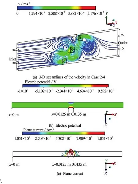
Fig.8 (Color online) Three-dimensional streamlines of the velocity, distributions of the electric potential and plane current in the midx-zplane (y= 0.0025 m) in Case 2-4
3.3 Mass fractions in Case 1 and Case 2
In the present study, Fluid A with the concentration of 1 is inhaled into the microchannel through the upper inlet region, while Fluid B with the concentration of 0 is sucked through the lower inlet region (see Fig.1). If the two fluids are perfectly mixed after the mixing process, the concentration of the fluids would be 0.5.
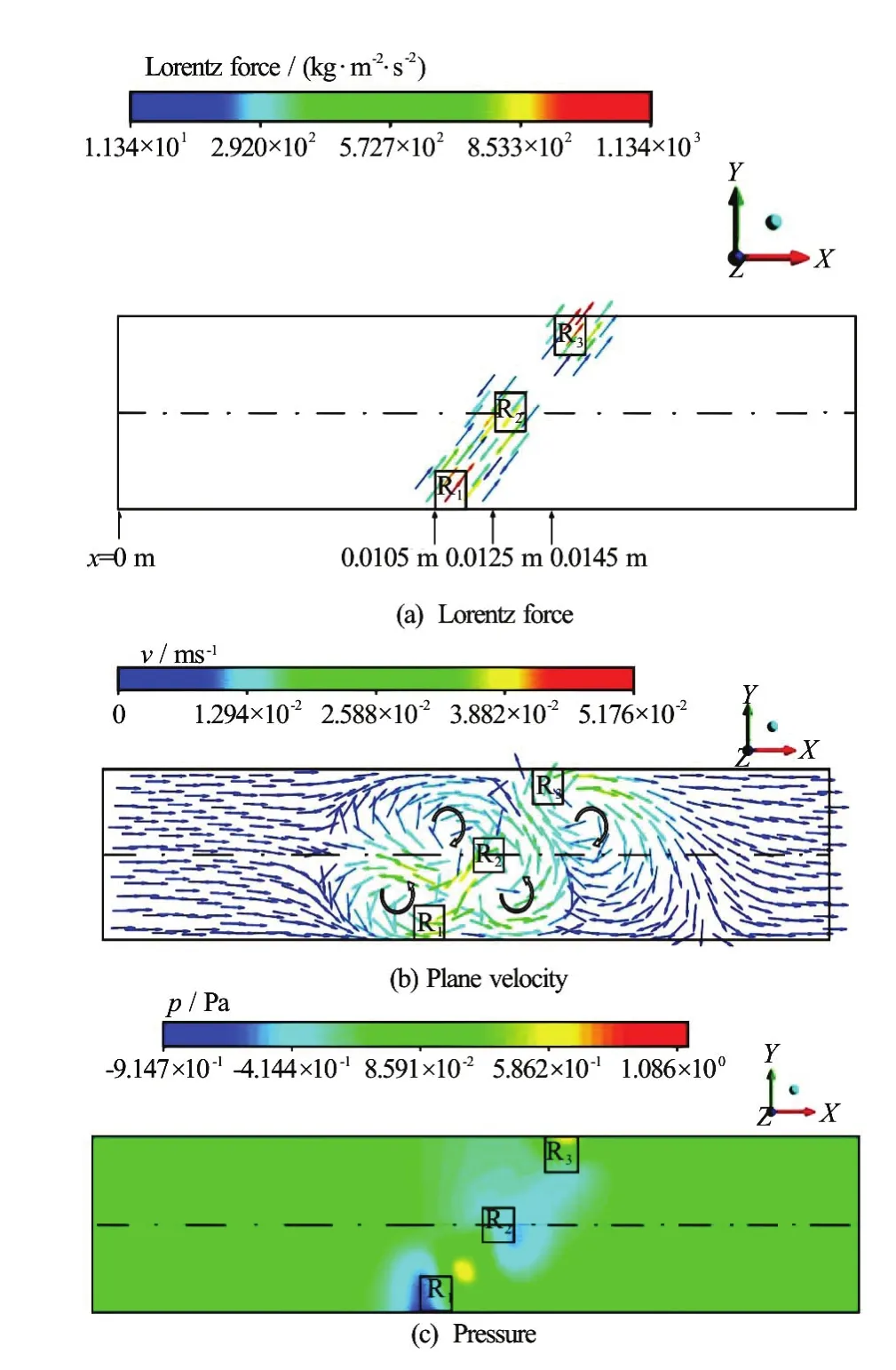
Fig.9 (Color online) Distributions of the Lorentz force, velocity and pressure in the midx-yplane (z=0.0005m)in Case 2-4
Since the absolute values of the applied voltages in Case 1 and Case 2-4 are the same, the comparison of the concentrations of the flow field in the two cases is meaningful. Figure 10 shows the mass fraction (concentration) distributions of the flow field in Case 1 and Case 2-4. In both the cases, the two fluids are not practically mixed near the inlet, so the concentration in the part of Fluid A is nearly 1 and that in the part of Fluid B is nearly 0, therein. In the fluid region near the electrodes, the two fluids are somewhat mixed, as depicted in Fig.10. Here, the concentration near the outlet is nearly 0.5, showing that the mixing efficiency is high. To the left of R1, R2and R3, larger green colored part with mass fraction of approximate 0.5 is seen in Case 2-4 (see Fig.10(b)), indicating that higher mixing performance is obtained therein, compared to Case 1 (see Fig.10(a)). It is caused by the fluid motion in the negativex-direction, created by the clockwise fluid circulation (in the fluid region to the left of R2) and by the anti-clockwise fluid circulation (in the fluid region to the left of R1).
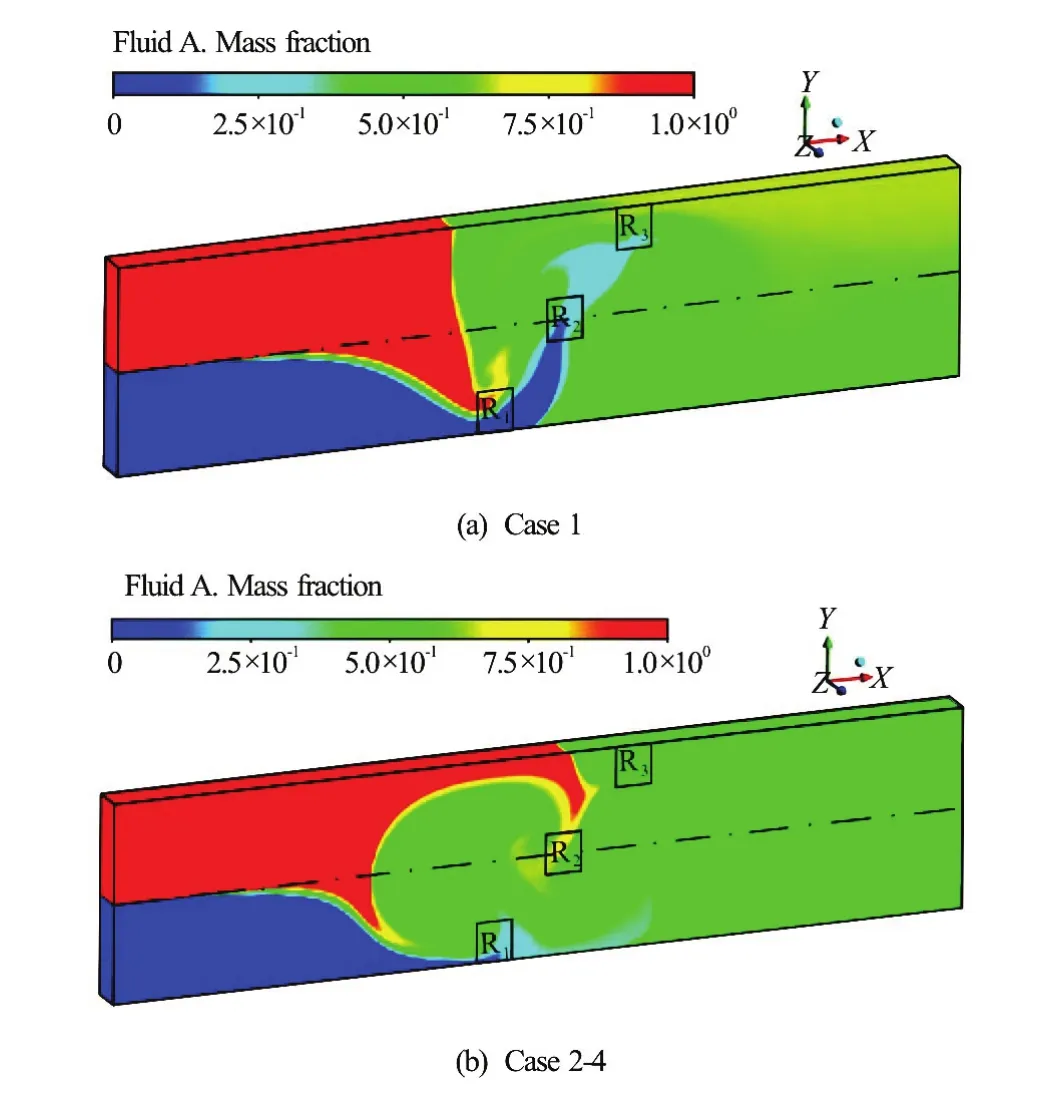
Fig.10 (Color online) Distributions of the mass fraction (concentration) of the flow field in Case 1 and Case 2-4

Fig.11 (Color online) Distributions of the cross-sectional mass fraction (concentration) of the flow field atx=0.024m in Case 1 and Case 2-4
Meanwhile, the cross-section for the mass-fraction (concentration) display is chosen to be located 8.5wd(wd=1mm) downstream from the trailing edge of the latest electrode (that is,x=0.024 m ), as shown in Fig.1. If the axial distance for the mass-fraction display (the distance between the trailing edge of the latest electrode and the cross-section for the mass-fraction display) is too short, the axial velocity is not well distributed at the cross-section for the mass-fraction display, so that the value of the mass fraction of the fluids displayed may not be well distributed. Also, if the axial distance for the mass-fraction display is too long, the diffusion effect can be meaningful in the region ranging from the trailing edge of the latest electrode to the cross-section for the mass-fraction display. Figure 11 shows the mass-fraction distribution atx=0.024 m in Case 1 and Case 2-4. In Case 1 (see Fig.11(a)), the mass fraction is nearly 0.5 in the central fluid region of the plane, meaning an efficient mixing, but, the mixing results are not so good in the fluid region near the top and bottom walls (parallel to the z-direction in Fig.11(a)) of the duct. In Case 2-4 (see Fig. 11(b)), the mass fractions appear somewhat uniform in the fluid region, indicating that the mixing performance is good.
3.4 Mixing index in Case 1 and Case 2
To quantify the mixer’s performance, the mixing index ()αcan be used, which is defined as follows:
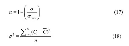
whereσmaxis the maximum standard deviation of the concentration of the fluids before entering the flow region, whose value is 0.5.σis the standard deviation of the concentration in a monitoring plane. In the present study, as mentioned before, the monitoring plane is chosen to be located at 8.5wd(wd=1mm) downstream from the trailing edge of the latest electrode.σcan be calculated by the Eq.(18), whereCiis the concentration fori-th cell in the monitoring plane,is the average concentration, andnis the total number of the fluid particles. If the two fluids are perfectly mixed, thenσ≈0, so that the mixing index will be 1, ifthen the mixing index will be 0. The mixing performance is higher when the value ofαis larger.
Table 3 shows the mixing indexes ()αand mass flow rates of Fluid A and Fluid B in all the cases. As mentioned before, the absolute values of the applied electrode voltages in Case 1 and Case 2-4 are the same (see Table 2) and the spatially alternating positive and negative potentials are applied on the electrodes in Case 2-4. Therefore, the comparison of the mixing index in the two cases can be meaningful. The mixing indexes in Case 1 and Case 2-4 are 0.78062, 0.99590, respectively, showing that the mixing performance can be highly promoted by imposing spatially alternating positive and negative electric potentials on the electrodes.
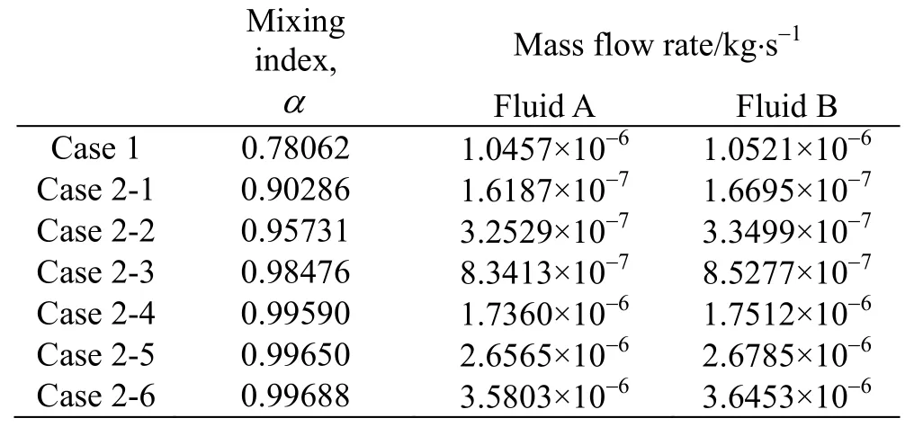
Table 3 Mixing indexes ()αand mass flow rates of Fluid A and Fluid B
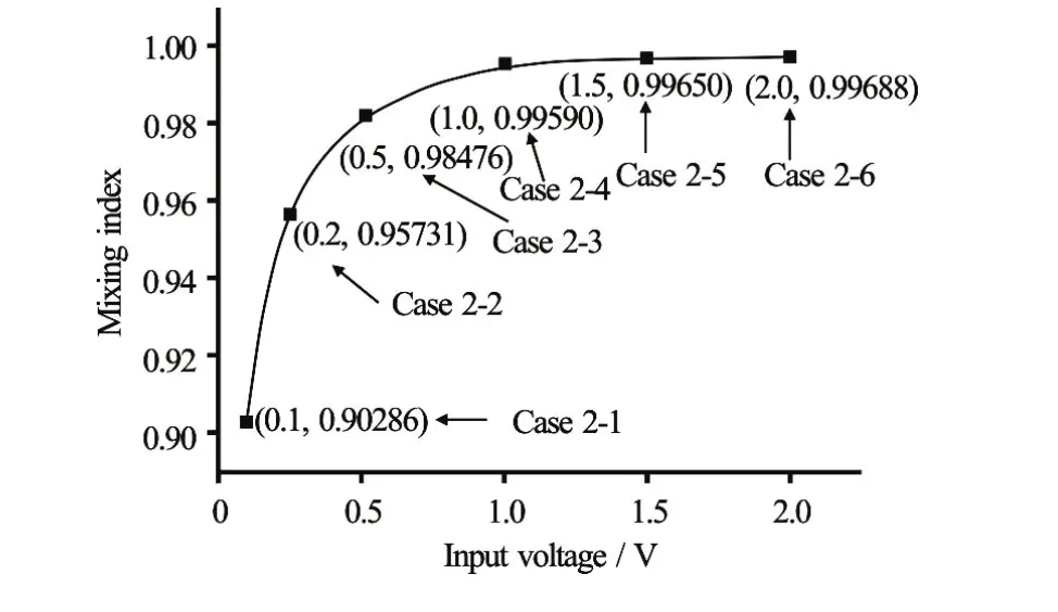
Fig.12 Mixing indexes ()αin the six subcases of Case 2, with the input voltages (absolute values) in the left and the mi xing index in the right of the parenthesis
It is to be noted that the applied electrode voltages (absolute values) in Case 2-1, Case 2-2, Case 2-3, Case 2-4, Case 2-5 and Case 2-6 are 0.1 V, 0.2 V, 0.5 V, 1.0 V, 1.5 V, 2.0 V, respectively (see Table 2). Table 3 presents the mass flow rates of Fluid A and Fluid B in the six subcases. Here, the difference in the mass flow rate of the two fluids in Case 2-6 is around 2.0%, while those in Case 2-4 and Case 2-5 are around 0.83% and 0.87%, respectively. If the voltage (absolute value) imposed on the electrode is too high, the difference in the mass flow rate of the two fluids cannot be negligible. Figure 12 shows the mixing indexes in the above-mentioned six subcases. The comparison of the mixing index in the six subcases leadsto the conclusion that the mixing index increases as the applied electrode voltage (absolute value) increases. With higher input voltage (absolute value) of the electrode, the Lorentz force is stronger with higher velocity, yielding higher mixing performance. As can be seen in Fig.12, the gradient of the mixing index curve becomes smaller when the input voltage is larger than 1.0 V, indicating that there is no significant increase in the mixing performance. For example, when the input voltages (absolute values) are 1.0 V, 1.5 V, the corresponding mixing indexes are 0.99590, 0.99650, respectively, whose difference is just 0.06%. Since the application of higher input voltage (for example, above 1.0 V) has no significant promotion in mixing performance, the voltage (absolute value) imposed on the electrode cannot be too high.
4. Conclusions
An rectangular electromagnetic mircomixer with pumping function is newly devised, and the flow features in the mixer are numerically investigated in the present study. Commercial software CFX is used to solve the governing equations. The accuracy and reliability of CFX code in the present numerical simulation is validated. In the present mixer, the current can be induced by applying different electric potentials to different electrodes. The combination of the induced current and magnetic field induces Lorentz force, which can be used for pumping as well as mixing.
In order to quantify the mixing performance, the mixing index is defined in the study. The investigation of mixing performance is carried out in different cases with different combinations of input voltage of the electrode. The results show that the mixing performance can be enhanced by applying spatially alternating positive and negative potentials to the electrodes. And, the mixing index is higher with higher input voltage (absolute value) of the electrode.
In summary, this study designs a new rectangular electromagnetic mircomixer with pumping function, and numerically examines the mixing performance for two different electrolyte solutions in a uniform magnetic field. The current numerical results show that the mixing performance can be enhanced by applying spatially alternating positive and negative voltages to the electrodes.
Acknowledgement
This work was supported by the National R&D Program through the National Research Foundation of Korea (NRF) funded by the Ministry of Education, Science and Technology & Ministry of Knowledge Economy (NRF 2011-0022679).
[1] Boehm D., Gottlieb P., Hu S. On-chip microfluidic biosensor for bacterial detection and identification [J].Sensors and Actuators B, 2007, 126(2): 508-514.
[2] Nguyen N. T., Wereley S. T. Fundamentals and applications of microfluidics [M]. Boston,USA: Artech House Publishers, 2006.
[3] Lim S., Choi B. A study on the MHD micropump with side-walled electrodes [J].Journal of Mechanical Science and Technology, 2009, 23(3): 739-749.
[4] Jang J., Lee S. Theoretical and experimental study of magneto-hydrodynamic (MHD) micropump [J].Sensors and Actuators A: Physical, 2000, 80(1): 84-89.
[5] Lemoff A. V., Lee A. P. An AC magneto-hydrodynamic micro-pump [J].Sensors and Actuators B, 2000, 63(3): 178-185.
[6] Zhong J., Yi M., Bau H. H. Magneto-hydrodynamic (MHD) pump fabricated with ceramic tapes [J].Sensors and Actuators A: Physical, 2002, 96(1): 59-66.
[7] Yi M., Bau H. H., Zhong J. A minute magneto hydro dynamic (MHD) mixer [J].Sensors and Actuators B, 2001, 79(2-3): 205-213.
[8] Qian S., Zhu J., Bau H. H. A stirrer for magneto-hydrodynamically controlled minute fluidic networks [J].Physics of Fluids, 2002, 14(10): 3584-3592.
[9] Affanni A., Chiorboli G. Development of an enhanced MHD micromixer based on axial flow modulation [J].Sensors and Actuators B, 2010, 147(2): 748-754.
[10] Lee S. H., Kang H. J., Choi B. A study on the novel micromixer with chaotic flows [J].Microsystem Technologies, 2009, 15(2): 269-277.
[11] La M., Kim W., Yang W. et al. Design and numerical simulation of complex flow generation in a microchannel by magnetohydrodynamic (MHD) actuation [J].International Journal of Precision Engineering and Manufacturing, 2014, 15(3): 463-470.
[12] Fang Y., Ye Y., Shen R. et al. Mixing enhancement by simple periodic geometric features in microchannels [J].Chemical Engineering Journal, 2012, 187(2): 306-310.
[13] Hutchinson B. R., Raithby G. D. A multigrid method based on the additive correction strategy [J], Numerical Heat Transfer, 1986, 9(5): 511-537.
[14] Raw M. Robustness of coupled algebraic multigrid for the Navier-Stokes equations [C].AIAA 34th Aerospace Science Meeting and Exhibit. Reno, USA, 1996, 96-0297.
[15] Shercliff J. A. A textbook of magnetohydrodynamics [M]. Oxford, UK: Pergamon Press, 1965.
[16] Walker J. S. Magnetohydrodynamic flows in rectangular ducts with thin conducting walls [J].Journal De Mecanique, 1981, 20(1): 79-112.
[17] Mistrangelo C. Three-dimensional MHD flow in sudden expansions [C].Wissenschaftliche Berichte, FZKA-7201 (M?rz 2006) Dissertation. Karlsruhe, Germany: Forschungszentrum Karlsruhe, 2006.
(Received August 12, 2015, Revised May 10, 2017)
*Biography:M. M. Wen (1992-), Female, Master Candidate
C. N. Kim,
E-mail: cnkim@khu.ac.kr

- 水動力學(xué)研究與進展 B輯的其它文章
- ICHD’ 2018 The 13th International Conference on Hydrodynamics First Announcement
- Cavitation erosion in bloods*
- A GPU accelerated finite volume coastal ocean model*
- A numerical study of violent sloshing problems with modified MPS method*
- Numerical investigation of entropy generation and heat transfer of pulsating flow in a horizontal channel with an open cavity*
- Numerical simulation of hydraulic force on the impeller of reversible pump turbines in generating mode*