
A fast and precise three-dimensional measurement system based on multiple parallel line lasers
2021-03-11 08:32:26YaoWang王堯andBinLin林斌
Chinese Physics B 2021年2期
Yao Wang(王堯) and Bin Lin(林斌)
State Key Laboratory of Modern Optical Instrumentation,CNERC for Optical Instruments,Zhejiang University,Hangzhou 310027,China
Keywords: three-dimensional shape measurement,multiple parallel line lasers,fast and precise measurement,parameter calibration
1. Introduction
Three-dimensional (3D) optical profilometry has been widely applied in many fields such as medical diagnoses,[1]automatic navigation[2]3D reconstruction[3,4]and vehicle assembly[5]for its advantages of non-contact,high speed and high precision. In industrial application scenarios,it is mostly extensively utilized to locate the defects of the object by measuring the 3D profile of the object and matching against the standard model.[6]Three-dimensional measurement techniques are of vital significance for accelerating industrial manufacturing,creating faster and more accurate 3D measurement techniques are constantly essential.
Optical 3D measurement techniques based on triangulation are widely applied in industrial fields today. One of them is the relatively mature fringe projection profilometry(FPP) technique[7]that extracts the parameters required for triangulation calculation from the phases of the light field.This method contains the optical sensor combining a camera and a digital light projection (DLP) device, where multiple cameras[8,9]gain the complete profile of the object, and the projection device varies from projectors to micro-mirrors.[10]The projected fringe is meticulously coded, the phase of the projected light fringe modulated by the surface of the object is calculated through algorithms,[11,12]and the 3D profile is restored according to the phase information.[13]Classic phase extraction algorithms include the three-step phase shift method[14]and the Fourier transform method.[15]
Another measurement technique based on the principle of laser triangulation is more widely applied in the field of industrial precision measurement due to its advantages in measurement accuracy. Its simplest implementation is to project a point or line laser light to scan the object under the drive of a motor. The laser moves and the whole surface of the object is scanned, and the surface is reconstructed at a subpixel level[16]by means such as point cloud processing,which can meet the accuracy requirements in industrial applications.However,this measurement method is limited by the scanning time, and it is inefficient and cannot meet the industrial online production rhythm when measuring the surface of larger objects. An apparent improved method is to exploit multiple line laser for projection to improve efficiency. Wu et al.[17]advised a novel multi-line structured light 3D profile measurement system, which can be use to calculate height of the circular tube by calibrating the light plane. At present,an experimental method that achieves higher measurement accuracy by calibrating the light plane[18]mainly includes three components: camera calibration, fringe center-line extraction, and line laser parameter calibration. After the three steps,the calculation of the profile is carried out by light plane correction.Meanwhile, some scholars have proposed a method of deriving the multiple light plane function[19]to reduce the calibration process,but it is too dependent on the choice of two light planes during initialization. To attain the object’s height information through the collected fringe changes,a model-free calibration method can also be applied.[20]The core of this idea is to perform polynomial fitting by accomplishing the offset of the fringe position on the imaging surface at different height positions through systemic calibration. However, the calibration process is too complicated,relies on motor movement and has low accuracy to meet the needs of the detection scene. In response to the above calibration problems,Li et al.[21]found that the height and phase deviation satisfy a polynomial relationship, and they applied the polynomial interpolation technique to complete the calibration. Despite many attempts,the calibration process of this multi-line laser system is still relatively complicated and requires a lot of time to calibrate.
In comparison of these two optical 3D measurement methods based on the principle of triangulation,the structured light source is spatially encoded and projected onto a surface,and the phase information at locations where the position changes drastically is modulated and compressed, reducing the measurement accuracy. This method can exploit an advisable algorithm to quickly obtain the profile of the entire object from a single image or several images,but at the cost of measurement accuracy. The laser triangulation method obtains the profile of the object by time-coding the light source and scanning, the modulated information of the imaging laser line is not compressed by the object,thus the method sacrifices measurement efficiency in exchange for higher accuracy. Moreover,the measure method of structured light is usually greatly altered by ambient light,therefore the measurement accuracy is greatly reduced with the distance of the object. This method based on triangulation is only suitable for short-distance measurement conditions for those problems. On the contrast, the laser light source is widely exploited in the field of industrial precision measurement for the advantages of high intensity and advantageous directionality,which makes it applicable to measurement scenes of different sizes,from small objects like workpieces to flatness detection of large steel plates. The size design of the line laser system can be flexibly changed with the scene to be detected. The resolution of the system becomes smaller as the detection object becomes larger,ranging from the micrometer level to the millimeter level.
Two coding methods of light source from the temporal or spatial dimension are coordinated for some 3D measurement scenarios that require balancing the accuracy and the efficiency.
This paper states a 3D rapid and precise method based on multiple parallel line lasers, which utilizes a multi-line laser,whose light planes are parallel to each other,plus a single camera for height data acquisition. Through derivation and establishment of the relationship between fringe offset and object height,only several systemic parameters need to be calibrated to complete the profile measurement of the 3D object. At the same time, the limiting conditions of the spatial frequency of the laser line are given, aiming at maximizing measurement efficiency while ensuring measurement accuracy by integrating the advantages of the structured light and laser triangulation methods. For some precise measurement scenes, a scanning motor is added to the system to micro-scan the object which makes it suitable for accelerated and precise measurement scenes in the industry.
The outline of the paper is as follows: In Section 2, we introduce the principle of the introduced system,establish the measurement model and derive the formula between the offset of the laser line and the height of the object,and give the spatial frequency limitation of the laser line.In Section 3,we simulate the influence of various parameters of the system on the measurement accuracy through Matlab,which has meaningful guiding significance for the selection of parameters. In Section 4, we build the platform, introduce the key experimental steps,and analyze the experimental results to verify the feasibility of the system through experiments. Section 2 gives the conclusions.
2. Principle of the system
In the current multi-line laser ranging system, the light planes of the projected light source are a fan-shaped divergence,[18]while the light planes offered in this paper are parallel to each other. One advantage of the feature is that the offset of each laser line on the imaging plane and the height of the position of the laser line are unified through the parameters of the system itself,thereby reducing system calibration parameters and improving calibration efficiency.
2.1. The distribution of the imaging line lasers
The laser source of the system emits a 2N+1 line laser array with equal intervals.The stripes are numbered,as shown in Fig.1,for the convenience of discussion.
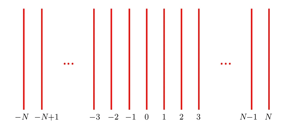
Fig.1. The numbered light laser array.
The laser line in the middle is called level 0 fringe, the multiple laser lines to the right are called levels 1, 2,... N,and the multiple laser lines to the left are called levels ?1,level ?2,...?N successively. After imaging through the lens,stripes will be generated on the imaging surface. The imaged fringes will be bent by different heights of the object to be measured, and the degree of bending will reflect the height information distribution of the surface.

Fig.2. Imaging positions of adjacent laser lines under the condition of different height differences: (a)normal,(b)overlap,(c)occlusion.
When the measured heights of two adjacent laser lines are on the same horizontal line, the result of the image is shown in Fig.2(a). As the height of the position where the left fringe locates decreases, the imaging line will shift closer to each other, until they coincide completely, see Fig.2(b). At this time, when the height difference between the position where two adjacent fringes continue to increase, the left fringe will not be imaged due to the occlusion of the object,see Fig.2(c).Therefore,the imaging fringe will not be overstepped,but the level of imaging fringe will be reversed. According to this imaging feature, the imaging position of the laser line can be determined sequentially from left to right on the imaging surface.
2.2. The formula for calculating the height
In the ranging system applying laser triangulation, the line laser emitted from the light source is reflected by the surface to be measured at different heights and the reflected light is imaged by the lens and its position is shifted. The offset information reflects the depth of the object. The relationship between the imaging offset and the object depth,which is established in the following, facilitates the measurement of the object height.
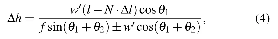
The line laser emits a beam of light, which is diffusely reflected on the base plane. The reflected light coincides with the optical axis of the lens, and the imaging line is formed at the center of the CCD placed on the focal plane of the lens,as shown in Fig.3. According to a simple geometric relationship, the relationship between the height difference, which is caused by different positions of the base plane and the object surface,and imaging offset can be derived as

where l represents the distance from the center of the lens to the base plane along the optical axis, f is the focal length of the lens,θ1is the incident angle of the laser line on the base plane,θ2is the corresponding reflection angle,w′is the imaging offset,and ?h is the height difference between the base plane and the object surface. Take sign+when the object plane is above the base plane,take sign ?otherwise.
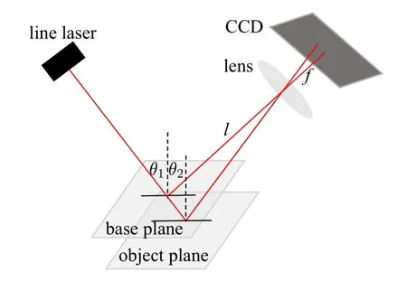
Fig.3. The model of the ranging system of the line laser.
The laser ranging model expressed by formula(1)is beneficial to the calibration of system parameters after the base plane of the line laser measurement system is determined.However, different laser lines correspond to different calibration parameters for a multi-line laser system. If each laser line is calibrated once,the process will be complicated.
Based on the evidence that different levels of laser lines correspond to base planes of different heights,this paper unifies the parameters of different laser lines by establishing a concept of multi-level base planes to simplify the calibration process.
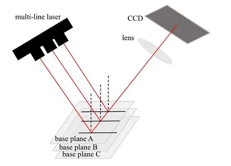
Fig.4. The diagram of the relationship among different base planes.
When a certain plane is the base plane of a line laser,its reflected light coincides with the optical axis of the lens. As the plane moves upward for some distance,it will become the base surface of the adjacent laser line on the right, and after moving down for some distance, it becomes the baseplane of the adjacent laser line on the left. For different levels of laser lines,the reflected light images on their respective base planes are imaged in the same position, which is the imaging baseline, as shown in Fig.4. According to a simple geometric relationship, the position relationship between adjacent base planes can be obtained. It can be expressed as
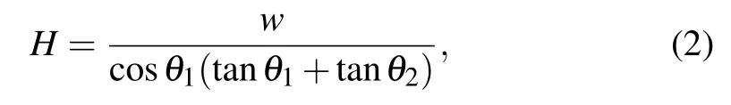
where w is the interval between adjacent laser lines,and H is the height difference between adjacent base planes.
In this way,the formula for the difference ?l between the system parameters l corresponding to adjacent laser lines can be obtained as follows:

After determining the base plane of the 0-level line, calibrate the values of the system parameters w,l,θ1,and θ2. For laser lines of other levels,simply replace the system calibration parameter value l calculated by Eq.(2),and the systemic formula of height measurement can be unified as
where w′is offset between the specific imaging laser line and the imaging baseline, ?h is the height difference between the base plane corresponding with specific laser line and object plane.
After introducing the concept of the multi-level base planes, the height information of the 3D object reflected by the offsets of the lines of all levels is unified into a framework,which facilitates the process of systemic calibration.
2.3. The spatial frequency of the line laser
When the height difference between two adjacent laser lines is greater than an actual value, the overlapping phenomenon of laser lines will occur on the imaging surface and cannot be distinguished. According to the analysis in Section 2.2,when the line interval w and the height difference ?H satisfy the following relationship:

no overlap phenomenon of laser lines occurs. When the overall height difference of the 3D object is known,the spatial frequency of the laser line can be determined according to this formula.
2.4. Measurement range
The measurement range of the system can be described as

where wmis the half-width of the CCD, N is the maximum level of the laser lines,and H represents the height difference between the baseplanes of the adjacent laser lines. Compared with the measurement system with a single laser line,the measurement range of the proposed system decreases as the width and number of the laser lines increase. In specific applications, it is necessary to balance the measurement depth and efficiency.
3. Simulation of the precision
Some scholars have conducted qualitative research on the system design[18]and found that the camera angle, the number of fringes and other parameters impact the resolution of the system. This paper quantitatively analyzes the parameters including focal length of the lens,the laser incident angle,and the reflected angle on the base surface of level 0 laser line,and the distance from the center of the lens to the base plane along the optical axis of the lens that influences the performance of the multi-parallel line laser ranging system.
In the simulation,the influence of various system parameters on the resolution is analyzed in a typical system by the method of controlling variables. Specially, the light of line laser is incident at an angle of 30?,the reflected angle between the axis of the lens and the normal of the base plane is 30?too, the focal length of the lens is 12 mm, the distance from the center of the lens to the base plane along the optical axis of the lens is 900 mm,and assuming that the distance between the centers of adjacent pixels of the camera to be 5.5μm. The resolution of this typical system is 0.4126 mm.
Here are the results of some simulations.
From the simulation, conclusions are drawn as follows:Firstly, the resolution of the recommended system decreases while the range of measurement increases with the increasing distance between the camera and the base plane, as shown in Fig.4(a). The resolutions under several values of l are presented in Table 1. Secondly,Fig.4(b)shows that the measurable depth of the system decreases as the incident angle of the laser line increases, and reaches the maximum when it is directly incident.The resolution linearity of the system becomes improved as the incident angle of the laser line increases,and the resolving capability is also enhanced. The resolutions corresponding to different incident angles are shown in Table 2.Thirdly,Fig.4(c)reveals that the depth of measurable volume and the resolution of the system both increase first and then decrease as the reflection angle increases. The resolution under the condition of several specific reflection angles are shown in Table 3. Lastly, the larger the focal length of the lens is, the smaller the measurable depth of the system is,and the higher the resolution is,see Fig.4(d). Specific resolution values under different focal lengths of the lens are listed in Table 4.

Fig.5. Resolution of the system for different parameters: (a)l,(b)θ1,(c)θ2 and(d) f.
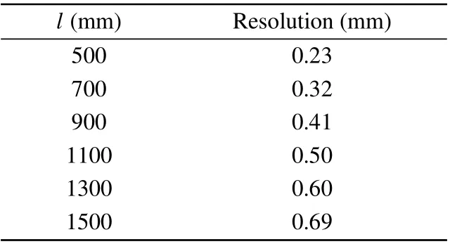
Table 1. Resolutions corresponding to different values of l.

Table 2. Resolutions corresponding to different values of θ1.

Table 3. Resolutions corresponding to different values of θ2.
In the laser triangulation system, the light source has evolved from a point laser to a line laser, which not only improves the measurement efficiency of the system but also reduces the measurable depth. Similarly, when the projected light is changing from line laser to multi-line lasers, it also brings an ample improvement in measurement efficiency,which requires to make a balance between efficiency and measurement depth,see Subsection 2.4. In actual applications,the appropriate number of laser lines should be selected according to the flatness of the measurement object,which has been discussed in Subsection 2.3.
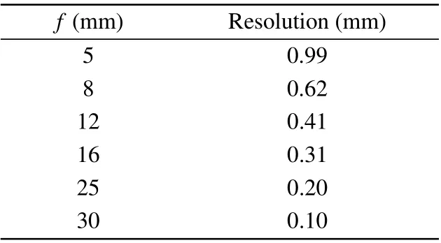
Table 4. Resolutions corresponding to different values of f.
4. Experiment
4.1. The steps of the experiment
To access the 3D profile of the object through this method,the following experimental approach is designed.
Step 1Calibration of the camera. The system calibration, which influences the accuracy, is a necessary link in the multiple parallel line laser ranging system,mainly including camera distortion calibration, and parameter calibration.Thus this step only considers the radial distortion of the camera, while ignoring the fine tangential distortion, and gains the distortion coefficient of the camera by Zhang’s calibration method.[22]The principle is to establish the relationship between the homogeneous 3D coordinate point M[X,Y,Z,1]and the homogeneous pixel coordinate point m[u,v,1]by establishing a pinhole camera model. The equality deduced in Zhang’s paper is described as

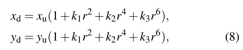
where s is a coefficient,A is the internal parameter of the camera,R and t are the external parameters of the camera. Then take the distortion of the camera into consideration, which is expressed as wherek1,k2,and k3are the coefficients of the camera’s radial distortion,xdand ydare the coordinates before the calibration of camera’s distortion, xuand yuare the coordinates after the calibration of camera’s distortion,and
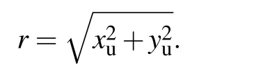
The internal parameters, external parameters, and distortion coefficient of the camera are calculated by the least squares fitting and two maximum likelihood estimations, which are stated in Zhang’s paper.[22]
In the camera calibration model, the introduction of the internal and external parameters is to complete the coordinate transformation from the world coordinate system to the pixel coordinate system. The difference is that the proposed algorithm does not need to obtain the integrated transformation matrix of the camera for the calibration step set up to calculate actual offset after acquiring the pixel offsets of each laser line on the image. Only the center point(u0,v0)of the camera is needed to establish the baseline and the distortion coefficient[k1, k2, k3]of the camera to carry out the distortion correction of the offset, and finally obtain the actual offset through the pixel size of the camera itself.
Step 2Systemic parameter calibration. The calibration of the system’s laser line incident angle θ1, the angle θ2between the optical axis of the lens and the normal of the base plane, the distance l from the center of the lens to the base plane along the optical axis, and the focal length of the lens f is completed in this step. The specific implementation is acquiring the four images of fringe offsets at different heights,calculating the offsets of the corresponding zero-level fringe in the pixel coordinates,and translating them in the world coordinate system through the size of the camera’s photosensitive element.Then perform camera distortion correction on the actual offsets and substitute the four sets of data into the height formula(1)to get the specific parameter values.
Step 4Centerline extraction. In this paper, the classic stripe thinning algorithm introduced by Steger[23]is exploited to extract the center of the laser lines,and the Hessian matrix is utilized to get the positions of the centerline of the stripes. From left to right, the offsets of pixel coordinates of each stripe’s center-line relative to their respective baselines are obtained. Finally, these pixel offsets are mapped into the actual position offset based on the camera calibration.
Step 5Height calculation. Substituting the actual offset into the height calculation formula(1),the 3D height values of the object at the locations of multiple laser lines are obtained.
Step 6Profile recovery. Based on the height data sampled from each laser line, the Sa function is followed to restore the surface of a 3D object. The restoration principle is expressed as

where Lsis the sampling period,which means the spatial frequency of the laser lines in this system,ωcis the bandwidth of the low-pass filter, and f(nLs) is the height data sampled by the multi-line laser system.
4.2. The result of the experiment
The following experimental platform,as shown in Fig.6,was built to verify the feasibility of the multi-line laser system in 3D measurement applications. The key optical components selected in the experiment are the camera,lens,and multi-line lasers.

Fig.6. The setup of the experimental system.
The main parameters of the camera are shown in Table 5,and the parameters of the lens are listed in Table 6.
Carry out the experiment shown in Subsection 4.1, and get the following experimental data.
First, perform distortion calibration on the camera given by the system. Print the checkerboard as shown in Fig.7,and get 13 calibration images under the environment of the experimental device. Apply the OpenCV’s calibration program to calibrate the camera, and get the distortion coefficient of the system camera. The matrix of radial distortion is [?0.1846415, ?0.1021654, 0.3264836]. The position of the baseline is determined according to the center point of the camera in the pixel coordinate system with the result of(1918.35,1373.92)in the experiment. The pixel offset can be converted into an actual one with these parameters including the pixel size of the camera,see Table 5.

Table 5. The main parameter of the camera.
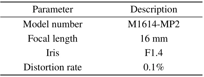
Table 6. The main parameters of the camera.
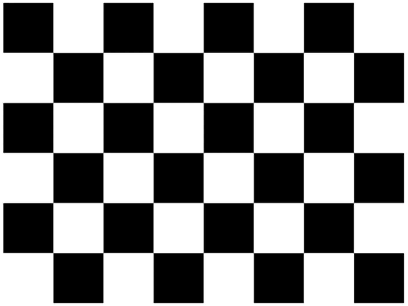
Fig.7. Printed checkerboard.
Then, the main parameter values of the system are calibrated by measuring the height changes and imaging offset at four locations. The calibration results of the specific systemic parameters are listed in Table 7.

Table 7. The result of parameter calibration.
The selected linear array light source produces 15 laser lines parallel to each other, and the distance between two adjacent laser line is 23.6 mm. The measurement range of this experimental system is calculated to be from 895 mm to 1017 mm, with a depth of 122 mm. In the experiment, 3D reconstruction was performed on the free-form surface shown in Fig.8. Place the measured surface in the camera’s field of view, and the multi-line laser is modulated into a line pattern as shown in Fig.9. It can be seen that the fringes do not overlap due to the morphology of the surface. Therefore, the line spacing of multiple laser lines in this system will not affect the detection accuracy.
The center-line extraction algorithm is applied to the modulated fringe image,and the division of the centerline extraction result is shown in Fig.10. The coordinates of the centerline of each fringe are acquired after the operation. After measurement,the maximum height difference between two adjacent lines is 9.527 mm,which meets the condition of formula(5)in Section 2.3. In practical applications,the specific height information of the object cannot be known in advance,the line space frequency of the multi-line laser can be determined according to the overall height difference of the object.

Fig.8. A measured 3D surface.
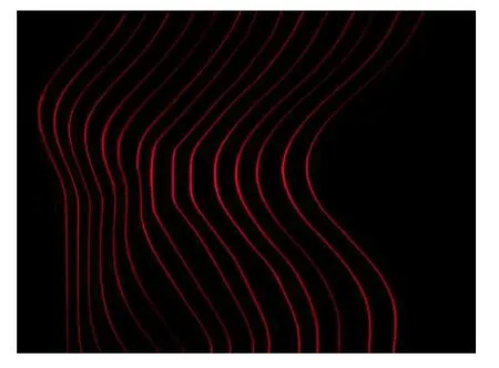
Fig.9. Modulated laser lines.

Fig.10. Division of center-line extraction result.
The essence of the multi-line laser ranging system is a spatial sampling system. This measurement method will reduce the lateral resolution of the system. For a flat surface,after selecting the right number of laser line stripes,you only need to snap a single picture to calculate and restore the 3D information of height.However,this kind of surface is rare in the real world,and there is often some more detailed information of height instead. To solve this problem, we can coordinate a multi-line laser system with the movement of the motor to scan the 3D surface to be measured by micro-displacement to access the height data at each position of the profile of the 3D object,thereby completing the task of 3D reconstruction.
Figure 11 is a result obtained by moving the free-form surface driven by the motor, collecting multiple positions at equal intervals,then sampling and restoring. It can be ensured that as the number of sampling lines increases,the effect of the restored surface is fitter. Figures 11(a)–11(d)are the results of the recovery from 1,2,4,and 8 images,containing 15,30,60,and 120 contours of multiple parallel laser lines,respectively.

Fig.11. Results of restoration with the different numbers of laser lines: (a)15,(b)30,(c)60,and(d)120.
4.3. Precision analysis
To analyze the accuracy of the system,we conduct the error analysis experiment in which a standard gauge block with a height of 8.095 mm was selected and placed under the line laser with a distance of 956 mm from the camera,see Fig.12.

Fig.12. Image of the measured standard gauge block.
The height of the gauge block calculated from the offset of the laser lines are listed in Table 8.
Repeated measurement to obtain a set of measurement values of the gauge block where the laser lines locate,the repeatability accuracy of the system is calculated to be 0.15 mm,and the maximum error of the system is 0.22 mm. The rms error(RMSE)of the height in the algorithm is 0.13 mm.
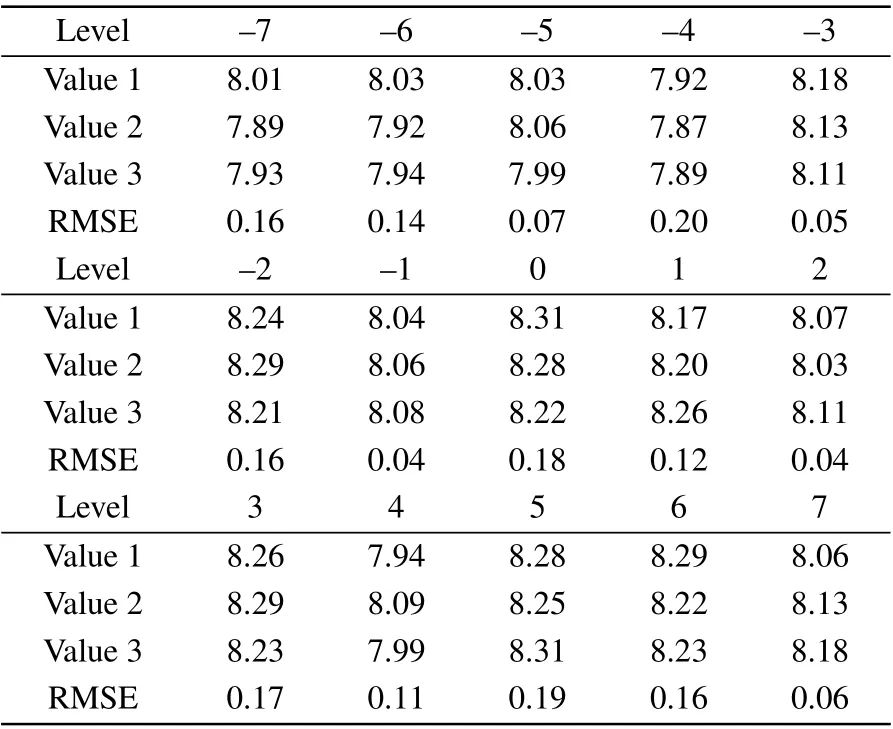
Table 8. The measured height of the gauge block.
The comparative result of systemic accuracy between the proposed technique and the two existing methods, one is the multiline structure light sensors scanning measurement system(MSSS)proposed by Gao et al.,[24]and the other is a singleshot structured light(SSSL)3D imaging technique that calculates the phase map from the distorted line pattern proposed by Wang and Yang,[25]as listed in Table 9.
It shows that the method proposed in this paper is more accurate than the method based on the structured light and the existing measurement technique based on the laser triangulation. It retains the accuracy advantage of the laser triangulation method.Compared with the traditional line laser scanning method,the multi-line laser scanning measurement greatly improves the measurement efficiency.
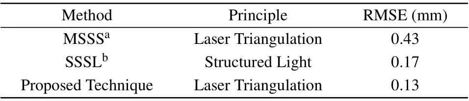
Table 9. Comparison and analysis with other existing methods.
5. Conclusions
We have proposed to utilize multiple parallel line lasers for 3D measurement system, which effectively balances high efficiency of spatial coding measurement method and high accuracy of time coding in the triangulation method.At the same time, the summary of the multi-line structured light imaging formula simplifies the calibration and calculation process of the system. Our simulation analysis of the impact of system parameters on the measurement accuracy provides support to the selection of system parameters for practical applications. The method improves the defect of low measurement efficiency in the line laser system, and can be effectively applied to the field of industrial rapid and precise measurement.In the experiment, 41220 points can be obtained per frame.Compared with the line laser 3D measurement system under the same conditions,the measurement efficiency is greatly improved. What’s more, the system has an accuracy better than 0.22 mm at a distance of 956.02 mm.

- Chinese Physics B的其它文章
- Statistical potentials for 3D structure evaluation:From proteins to RNAs?
- Identification of denatured and normal biological tissues based on compressed sensing and refined composite multi-scale fuzzy entropy during high intensity focused ultrasound treatment?
- Folding nucleus and unfolding dynamics of protein 2GB1?
- Quantitative coherence analysis of dual phase grating x-ray interferometry with source grating?
- An electromagnetic view of relay time in propagation of neural signals?
- Negative photoconductivity in low-dimensional materials?