
Numerical simulation and performance analysis of the radiofrequency inductive cathode
2023-03-06 01:49:30KuanQIAO喬寬MousenCHENG程謀森FanZHANG張帆XiongYANG楊雄DaweiGUO郭大偉YuntianYANG楊云天andZhenweiDING丁振偉
Plasma Science and Technology 2023年2期
Kuan QIAO (喬寬),Mousen CHENG (程謀森),Fan ZHANG (張帆),Xiong YANG (楊雄),*,Dawei GUO (郭大偉),Yuntian YANG (楊云天) and Zhenwei DING (丁振偉)
1 College of Aerospace Science and Engineering,National University of Defense Technology,Changsha 410073,People’s Republic of China
2 Beijing Institute of Tracking and Telecommunications Technology,Beijing 100080,People’s Republic of China
3 Chinese Unit 32032 of the People’s Liberation Army,Beijing 100080,People’s Republic of China
Abstract The radiofrequency (RF) inductive cathode has great prospects in space missions with long mission cycles,large speed increments,and rapid response requirements as the main electron source and neutralizer in Hall thrusters and ion thrusters.This paper proposes a comprehensive multi-physics RF inductive cathode model in which the RF electromagnetic field,electrostatic field for extracting electrons,flow field,plasma transport and electrochemical reaction process are all accounted for.Each physical field mentioned above can form a closed partial differential equation.The two-dimensional finite element code COMSOL is used to solve the multi-physics model.With this model,the formation process of the anode spot is exhibited and demonstrates the non-bipolar flow theory in practice.The simulation results demonstrate that the current jump in the RF inductive cathode is caused by the anode spot.Furthermore,the influences of preset discharge parameters such as RF power,bias voltage and actuating gas flow as well as structural parameters like the coil structure,discharge chamber size and ion collector area,emission hole size,distance between the anode target and the emission hole etc on the cathode performance are investigated,and some important optimal parameters are proposed.
Keywords: RF inductive cathode,electron current,anode spot
1.Introduction
Grid-type ion thrusters and Hall thrusters generally take a plasma bridge hollow cathode as an electron source,which depends on a hollow cylindrical solid-state thermionic emitter to maintain the plasma [1].The porous tungsten emitters impregnated with barium,calcium oxide and alumina are easily poisoned after contact with active gases like oxygen,strictly requiring the purity of the actuating gas and the application environment [2].Even though hollow cathodes with borides(e.g.LaB6) emitters have superior toxicity resistance,the evaporation and corrosion of emitter materials still limit their service time.In addition,the emitter should be heated to a high temperature (beyond 1000 °C) before stable operation,which normally takes about 2 min,limiting the application of the thruster in some fast-response missions.In recent years,the cold cathode has also been proposed to solve the problem of rapid start-up of electric thrusters [3].However,the current trial-produced cold cathodes have a relatively short lifespan,generally around 10 000 h,which is 10-20 times shorter than those of mainstream hollow cathodes.
The radiofrequency (RF) inductive cathode without thermionic emitters,which counts on inductively coupled discharge to generate dense plasma in the discharge chamber and a bias voltage to extract electrons,has become a research key point [4].Although the RF inductive cathode requires extra power to generate plasma,it has the advantages of low operating temperature,instantaneous start-up and compatibility of actuating gas to overcome the weakness of the hollow cathode.To date,multiple teams have carried out numerical simulations and experiments on the RF inductive cathode.An RF inductive cathode with the configuration exhibited in figure 1 was first proposed and successfully ignited by Hatakeyama T and Watanabe H [5].
For the cathode used for electric rocket propulsion,its performance can be evaluated by three parameters: electron currentIe,electron production costCeand actuating gas utilizationUe.The electron production cost is defined as the power consumed per 1 A electron current generated,and the actuating gas utilization is the ratio of the electron current emitted by the cathode to the ionic current corresponding to the complete monovalent ionization of the actuating gas.Table 1 summarizes the performance parameters of some representative RF inductive cathodes.Under an electron current of ~1 A,the electron production cost of the thermal emitter hollow cathode is about 30 W A-1,and the actuating gas utilization is about 30,whereas the corresponding two parameters of the present RF inductive cathode that has been trial-produced are 100-200 W A-1and 10-15.Therefore,the performance of the RF inductive cathode should be enhanced before application in electric thrusters.Moreover,it is found that the electron current is unstable and the working range is narrow when the RF inductive cathode is operated in conjunction with a Hall thruster [6].For the purpose of solving these conundrums,it is crucial to further examine the mechanism of the RF inductive cathode,observe the plasma morphology in the discharge chamber,and produce a set of techniques to improve the cathode performance.However,it is time-consuming and laborious to change the structural parameters of the cathode in experiments.Moreover,the plasma parameters in the discharge chamber are difficult to detect accurately with physical probes.Thus,a numerical model with high accuracy is urgently required.
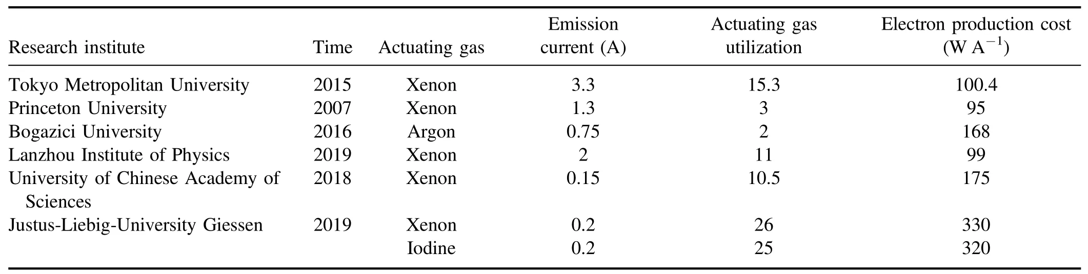
Table 1.Performance parameters of some representative RF inductive cathodesa.
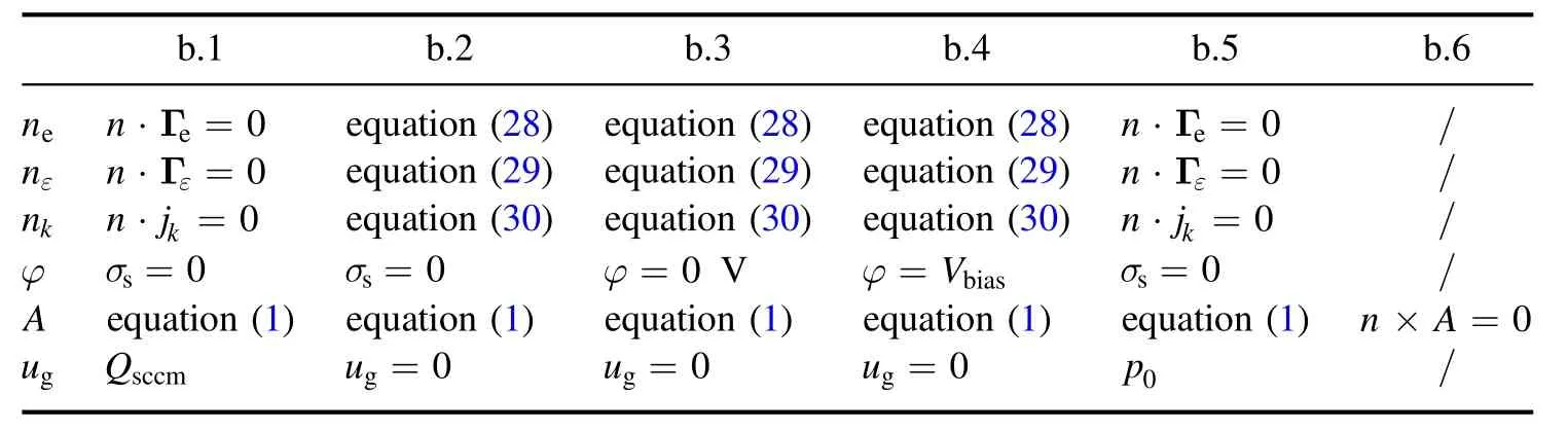
Table 2. Boundary condition settings.
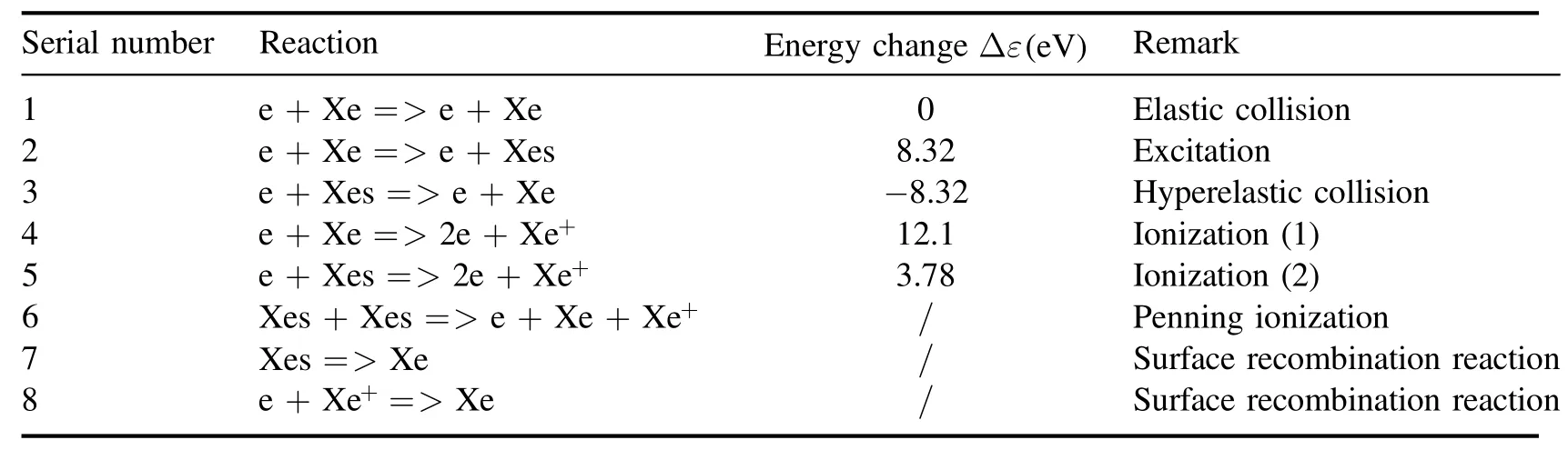
Table 3.Chemical reactions in the discharge chamber.
Early numerical models mainly pay attention to the RF ion thrusters,which can also be applied to the RF inductive cathode with appropriate modifications [14-17].However,these models,mainly focusing on discharge,are incapable of studying the process of extracting electrons.In 2014,Jahanbakhshet alestablished a 0D equivalent circuit model for the electron emission procedure of the RF inductive cathode to illustrate the formation of the anode spot [18].Moreover,they discussed the relationship between the sheath type at the emission hole of the RF inductive cathode,the ion collector area and the emission hole cross-section area [19],which was mutually verified with B Longmier’s non-bipolar flow theory[20,21].However,this model paid less attention to the discharge process and was limited by the spatial dimension,so it can only be used for analyzing the electron extraction process.In 2017,Scholze Fet alproposed a numerical model for a plasma bridge neutralizer,which can be used to optimize the design of the neutralizer [22].However,the model cannot represent the plasma state inside the discharge chamber,and as a 0D model,it is not suitable for two-dimensional or three-dimensional analysis.Most of the flow field models set up for the RF inductive cathode are used to investigate the discharge process [23-29],and less significance is attached to extracting electrons.Consequently,the numerical simulation approaches for the RF inductive cathode still need to be meliorated,and a multi-dimensional model that can directly reflect the plasma state parameters and exactly predict the cathode performance is required.
This paper is divided into sections as follows: section 1 briefly recommends the principle of the RF inductive cathode and the existing shortcomings of its numerical model;section 2 introduces the assumptions of the model,establishment of equations,solution conditions and solving techniques in detail; section 3 verifies the formation of the anode spot and reproduces the experimental data of the predecessors; section 4 discusses the effect of structural parameters such as coil structure,discharge chamber size and collector area,emission hole size,and distance between anode target and emission hole,and discharge parameters such as RF power,bias voltage and actuating gas flow on the RF inductive cathode performance;and section 5 summarizes the work of this paper.
2.Model
2.1.Object simplification and basic assumptions for the model
A two-dimensional axisymmetric simulation example exhibited in figure 2 is put forward,which comprehensively considers complex multi-physics processes such as the RF electromagnetic field,the electron extraction electrostatic field,the flow field,the plasma transport and electrochemical reaction.The discharge parameters to be used are: RF frequencyf=13.56 MHz,initial gas temperatureTg0=300 K,discharge chamber lengthLdis=25 mm,discharge chamber radiusRdis=20 mm,actuating gas flow rate 1.5 mg s-1,RF powerPRF=20 W,distance between anode and emission holeLanode=50 mm and background air pressurepref= 1 × 10⁻³Pa.Unless otherwise specified,all the parameters used in this article are the values above.
In addition to the above conditions,to simplify the calculation,the following assumptions are made for the model:
(1) The plasma is in a weakly ionized state.Much of the research[30]has shown that the plasma density is highly lower than that of neutral particles in the inductive discharge,which is consistent with the weak ionization hypothesis.
(2) Impact ionization is dominant in inductive discharge and can be simulated by the fluid equation.
(3) The electron energy distribution function (EEDF) of the main plasma region obeys the Maxwell distribution.
(4) The temperature of an ion equals that of an atom,which is significantly lower than the electron temperature.Additionally,there is no energy exchange between ions and atoms.
2.2.Model equations
2.2.1.Electromagnetic field equations.In this model,the electromagnetic field is divided into three parts: the first is the alternating electromagnetic field excited by the RF coil,the second is the electrostatic field formed by the plasma bipolar diffusion,and the third is the electrostatic field formed by the potential difference between the anode target and the collector.The alternating electromagnetic field satisfies Ampere’s law with the magnetic vector potential as the variable in the frequency domain,and the electrostatic field satisfies the Poisson equation with the electric potential as the variable.Rewriting Ampere’s law in the frequency domain gives
where j is an imaginary unit;ωis RF angular frequency;Ais magnetic vector potential;ε0is vacuum permittivity;μ0is vacuum permeability; andσis electrical conductivity.
Conductivity in inductively coupled plasma can be expressed as:
νeis the electron-neutral particle collision frequency,and its specific expression can be found in [31];neis the electron number density;eis the element charge; andmeis the electron mass.
The plasma potential can be expressed by the Poisson equation in a steady state as
whereρis the space charge density andVis the plasma potential,including the potential formed by the plasma bipolar diffusionV1and the electrostatic field potentialV2.By combining equations (1) and (3),the relationship of electromagnetic fields in plasma can be described.There are resistive lossesQrhin the propagating electromagnetic waves in plasma:
Among them,Re is the function of taking the real part;* is conjugate multiplication; andJis plasma current including the induced current and displacement current.
whereEmfis the alternating component of the electric field:
2.2.2.Flow field equations.In order to simplify the calculation of the model,the particle flow is regarded as a compressible steady flow,which is expressed as
whereIis the identity matrix;Kis the diffusion term; andμis the dynamic viscosity.
A gas inlet and outlet are set in the discharge chamber,and the input amount of the actuating gas isQ0(unit: s-1).Before the ionization of the actuating gas,the inflow and outflow of the gas are equal to the steady state.At this time,the pressure in the discharge chamber can be calculated according to the following formula:
wherekBis the Boltzmann constant;vg0is the initial thermal motion velocity of the gas molecules; andAoutis the crosssectional area of the emission hole.p0is set to the initial pressure in the chamber.Since the work environment of the RF inductive cathode is a vacuum,the initial pressure outside the chamber is set to 0.001 Pa.
It is worth noting that the parameters used to measure the actuating gas flow in this work areQ0,QsccmandQm,and the conversion relationship is as follows:
whereρgandmgare the density and the molar mass of the actuating gas.
2.2.3.Electron transport equations.The electron density and mean energy can be computed by solving a pair of drift diffusion equations for the electron density and mean electron energy.The electron density conservation formula is
whereReis the electron generation source term and Γeis the electron number density flux vector.Under the drift-diffusion approximation,the electron number density flux vector can be written as
The electron current density is
Integrating the axial component of electron flow density at the interface of the orifice outlet can obtain the electron current as
Assuming that the electrons do not deviate far from Maxwell distribution,linearizing the collision term of the Boltzmann equation can give:
whereTeis the electron temperature,measured in volts in this work.
Assuming that there areMreactions that generate electrons,the relationship between the electron generation source termReand chemical reaction raterkis
whereNAis Avogadro’s constant;cjis the molar concentration ofjcomponents in the reaction formula; andkf,kis the chemical reaction rate coefficient,defined by the collision cross-section of the reaction:
Among themσk(ε)is the collision cross-section of chemical reaction,which is a function of electron energy,and its discrete data can be obtained by query;f(ε)adopts EEDF distribution in hypothesis.
The electron average energy conservation formula can be written as:
wherenεis average electron energy density;Γεis the electron energy flux vector;Senis energy loss caused by the collision(including elastic collision and inelastic collision);andQdepis the energy density of the electromagnetic wave deposited into the plasma,whereQdep=Qrhunder the assumption of collision deposition [32].Qdepcan be integrated to calculate the RF power deposited into the plasmaPdep.
The electron energy flux vector can be written as
whereFis Faraday’s constant andd ke(in V) is the energychange value:
As for inelastic collisions,the loss of energy equals the energy in the specific chemical reactions.
2.2.4.Conservation equations of heavy particles.For nonelectron particles,the following equations for the mass fraction of each species are solved:
wherewkis the mass fraction of thek-component particle;jkis the diffusion flux vector of thek-component particle;andRkis the source term of the generation rate of thek-component particle.The temperature of the heavy particles usually changes little during the discharge process,ignoring its thermal diffusion effect,and the diffusion flux vector of thek-component particle under the drift-diffusion approximation is
The first term in parentheses is the concentration diffusion term,and the second term is the electric field migration term.Dk f,is the diffusion coefficient of thek-component particle;zkis the charge of thek-component particle; andμk f,is thekcomponent particle mobility.Since the influence of the magnetic field on the macroscopic distribution of ions is ignored in the simplified model,the transport parameters of ions are all constant without the magnetic field term.
The heavy particle generation source term is determined by chemical reaction:
In the above formula,υk j,is the stoichiometric coefficient of chemical reaction,rjis the reaction rate ofjreaction,andMkis the molar mass of heavy particles.
Assuming that there areQkinds of non-electron heavy particles,there will beQ-1 mutually independent equations (23) and a mass conservation constraint equation (27),which can be solved simultaneously.
2.3.Definite solution conditions
2.3.1.Boundary conditions.For the sake of forming a unified analysis of the whole-domain plasma including the sheath,the solid-wall flux boundary conditions of each particle state are derived in this paper.The random motion of electrons near the wall within a few mean free paths causes it to be lost on the wall and produced due to the secondary emission effect,thus giving the following boundary conditions of electron flux:
wherenis normal element quantity (inward is positive);ve,this electron thermal velocity; andreis the wall reflection coefficient.The electron energy flux lost by the wall is
As for heavy particles,the change in the particle number is not caused by thermal motion but controlled by the chemical reaction on the surface or the electric field at the wall.Therefore,the diffusion flux vector at the wall can be defined as
whereinRk,ckandμkare the surface chemical reaction rate,molar concentration and diffusion coefficient of thekcomponent particles,respectively.
The solution domain is shown in figure 2,and the corresponding boundary conditions are shown in table 2.In order to restore the actual operating condition of the RF inductive cathode,d.6 is set as the ion collector.Since the ion collector could not be set as a cylinder with slit limited by two-dimensional form,and a metal cylinder with no slit would completely shield the RF power,the collector was set as the same material as that of the discharge chamber in the two-dimensional model.To compensate for the deviation caused by this assumption,a three-dimensional model was developed to calculate the effect of the metal collector on RF power transfer.The next chapter will describe in detail how to approximate the analysis with the three-dimensional model.For a true quartz discharge chamber wall,surface charge does not accumulate,so the surface charge density is set to 0.
2.3.2.Chemical reactions.Inductively coupled plasma discharge is a non-thermodynamic equilibrium process,and the secondary ionization can be negligible due to the low RF power.Under low pressure,the chemical reaction mechanism of noble gas elements is relatively simple.As shown in table 3,the chemical mechanism of Xe is represented by only three species and six groups of reactions.In addition,the recombination reactions of excited Xe atoms and Xe ions are also considered at boundaries.Among the excited states of Xe,the metastable energy level has the greatest influence on the characteristics of plasma discharge process.In this paper,the most important metastable energy level,4s[3/2]2(the metastable state of the spin triplet state of the 4s energy level),is selected as the representative of the excited state.By the same token,only the first-order discharge is considered for the inductively coupled discharge of Ar in the process of chemical reaction and analogy of table 3.
2.4.Solving techniques
2.4.1.Collector approximation.The metal collector inside the RF inductive cathode has a certain shielding effect on electromagnetic waves,thereby triggering the power loss.The ion collector cannot be restored in the two-dimensional model.Therefore,based on COMSOL,a three-dimensional model is established as shown in figure 3 to calculate the power loss caused by the metal collector.
When the frequency of the RF power source is 13.56 MHz,the skin depth of the current in the copper coil isμ17.94 m.For the three-dimensional model,an excessively refined mesh increases the degree of freedom of partial differential equations (PDEs) in series.Due to the limitation of computing power,it is often challenging to create a mesh which has the ability to resolve high-frequency currents.Therefore,in this work,the impedance boundary condition is used to define the excitation mode of the RF coil,and only the coil current and electric field on the coil surface are calculated without dividing the coil into a three-dimensional mesh.This technique does not affect the actual electromagnetic field distribution or coil power consumption,but greatly simplifies the calculation process.The electromagnetic field excited by a current source under an impedance boundary condition can be written in the following format:
whereinεr,μrandσare the relative permittivity,relative permeability and electrical conductivity of the coil material,respectively,andJais the current density on the surface of the coil (unit here is A/m).
Similarly,the collector material is generally metal,so the collector can also be analyzed with the impedance boundary condition.The power deposited into the plasmaP3Ddep,the power dissipated by the coil and the collectorP3Dc,total powerP3Dcan all be solved by integratingQdep,defining the power transmission ratio as
If the actual input RF power isP,then the power in the two dimensional model should beP* =rPP.By combining a two-dimensional axisymmetric model and a three-dimensional model,calculation can be greatly simplified while ensuring accuracy.
2.4.2.Logarithmic transformation.The drift-diffusion transport equation is highly nonlinear,especially in the plasma sheath,where the plasma electron number density,electron average energy density and other parameters have large spatial gradients.It is found that the equation solving is more stable by transforming the transport governing equation with the logarithms of electron number density,electron average energy density and mass fraction of heavy particles as independent variables.
2.4.3.Computational domain mesh.In terms of the mesh,the main body of the solution domain adopts a triangular mesh.Since the plasma parameters change drastically in the sheath,a quadrilateral boundary layer mesh is used near the walls of the chamber.The thickness of the boundary layer mesh is in a geometric sequence with a proportional coefficient of 1.2.There are 16 layers in total.The thickness of the first layer is determined by the boundary Debye length according to equation (36):
The RF coil adopts a triangular boundary layer mesh due to the skin effect.The thickness of the boundary layer mesh is also in a geometric sequence with a proportional coefficient of 1.2.There are eight layers in total,and the thickness of the first layer is the skin depth of the current in the coil.
The specific division of the spatial mesh is shown in figure 4.In the calculation,the finite element scheme of the linear shape function is used to discretize the spatial grid points,and a backward difference scheme is employed as time discretization.Specifically,the adaptive time step technique of the COMSOL Multiphysics TM solver is adopted,and the initial time step is 1 × 10-16s.
The interconnection of the main physical fields of the model is shown in figure 5.The three physical fields constitute independent closed PDEs with definite solution conditions,transferring parameters to each other.
3.Theory verification and experimental data reproduction
3.1.Theory verification of non-bipolar flow
The current jump phenomenon occurs when the RF inductive cathode works,that is,the electron current suddenly increases with the bias voltage (actuating gas flow).The non-bipolar flow theory proposed by B Longmier points out that the current jump is a result of the formation of an anode spot [20].Non-bipolar flow refers to an ideal state in which all ions are‘absorbed’ by the collector and all electrons flow out of the emission hole,and the plasma forms an anode spot.In other words,with increasing bias voltage,when the energy obtained by newly ionized electrons from the acceleration process in the main plasma region exceeds the ionization energy of neutral particles,ionization occurs in the sheath near the emission hole,resulting in a change of plasma structure and the formation of an anodic glow.When the electrons and ions in a Debye cube within the anodic glow are roughly the same density,the anode spot forms around the emission hole.Due to the quasi-electric neutrality of the anode spot,its formation is equivalent to expanding the area of the emitter hole outlet into the surface area of the spherical region,which causes the electron current to increase abruptly.
Since the RF inductive cathode discharge chamber shown in figure 2 is small,the distance between the emission hole and the plasma source is too close,meaning that the anode spot formed at the emission hole is hard to observe.The structure is changed to one shown in figure 6,in which the emission hole is kept away from the plasma source to observe the anode spot easily.
Baalrudet alproposed that the electron sheath should be formed before the forming of the anode spot [21].The structure of the sheath near the anode depends on the ratio of the areas of the electron collector and the ion collector,
whereMiis the ion mass;Aeis the electron collection area;andAiis the ion collection area.It is proposed that the electron sheath forms when
In the RF inductive cathode,Aeis the area of the emitting hole andAiis the area of the ion collector.In the calculation example in this paper,the area ratios are all in line with the requirements of formula (38).
As shown in figure 7,when the RF inductive cathode works stably,its internal plasma structure is in a relatively fixed geometry.Apart from the plasma source near the coil with the highest plasma density,there is also a globular high-density plasma group at the emission hole,namely the anode spot.
To clearly demonstrate the formation of the anode spot,the plasma morphology at the emission hole under different actuating gas flows is simulated.It is found that the actuating gas flow has a minimum below which the plasma in the chamber is unable to form the anode spot.Even though the electrons near the emission hole have been accelerated to high energy by the electrostatic field,which is high enough to inspire the collision ionization process on the neutral particles,the inelastic collision frequency is so low that the anode spot cannot be formed.However,the accumulated ionization around the emission hole allows the structure of the sheath to be changed and the anodic glow to be formed.Moreover,the inelastic collision frequency increases with the actuating gas flow,and the anode spot forms when the Debye cube in the anode glow becomes quasi-electrically neutral.As the actuating gas flow continues to grow,the size of the anode spot is increased,leading to growth of the electron current.Furthermore,once the actuating gas flow rises to a certain critical value,the size of the anode spot reaches its maximum,and the plasma density in the chamber stops growing due to the limitation of RF power.Additionally,along with the increasing actuating gas flow,the energy exchange between electrons and neutral particles due to collisions is more frequent,bringing about a boost in the electron number and a decay in the electron energy.The change of anode spot structure in figure 8 is consistent with the above description,verifying that the size of the anode spot expands with the rising actuating gas flow,but the electron temperature begins to fall.
3.2.Reproduction of experimental data
Watanabeet al[35]carried out experiments on an RF inductive cathode,using probes and circuit instruments to explore the effects of RF power,bias voltage,coil turns and other parameters on the electron current and plasma parameters.In this work,a validation example is reconstructed to reproduce experimental data.
The simulation results shown in figure 9 are not only numerically comparable to the experimental ones but also maintain a superior agreement with the current jump interval.The simulated electron current is higher than that of the experiments,which is attributed to the fact that actual area of the ion collector in the Watanabe’s experiment is unknown.In this model,the collector area is set as the area of the entire side wall of the chamber,but in fact the collector is an open cylinder and its length may vary according to the chamber length.The electron current will not rise when the bias voltage reaches a certain value,which is marked with triangles in figure 9,because the anode spot will not grow.At this time,the corresponding bias voltage is called saturated anode voltage,and the electron current is called saturated electron current.
Figure 10 depicts the changes in bulk plasma potential,electron number density and electron temperature with bias voltage during the formation of the anode spot.Figure 10(a)shows that the bulk plasma potential exhibits little change before the electron current jump but locks to the bias voltage after the electron current mutation,proving that there is a transition from the electron sheath to the anode spot in the region of 0-20 V.This is consistent with the experimental conclusion in [35],and this phenomenon is called plasma potential locking.As shown in figure 10(b),the electron temperature and electron number density at the emission hole will rise rapidly during the formation of the anode spot,and will not change when the anode spot size reaches the maximum.It should be pointed out that except for figure 12(b),the detection points of electron temperature and electron density are on the axis of the discharge chamber and 1 mm away from the emission hole.What is more,when detecting the electron density and the electron temperature,the bias voltage is set to zero apart from figure 10(b).

Figure 1.Schematic of an RF inductive cathode.
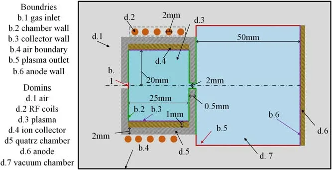
Figure 2. Schematic of the two-dimensional axisymmetric model.
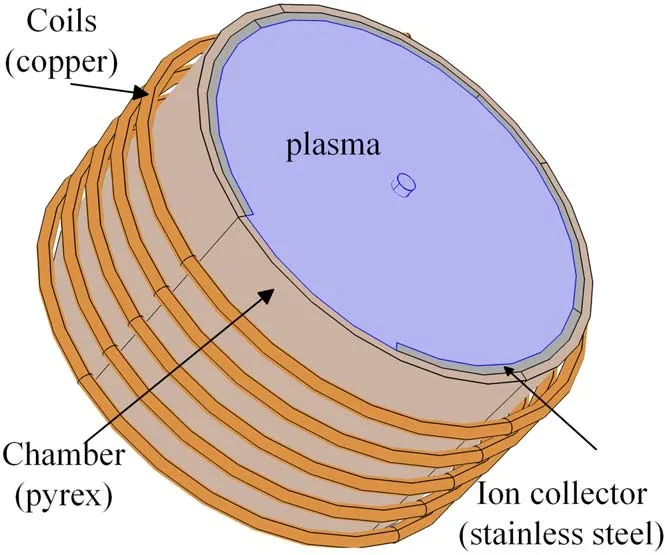
Figure 3. Schematic of the three-dimensional model.
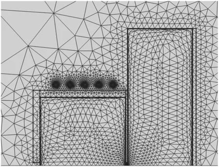
Figure 4. Mesh division schematic.
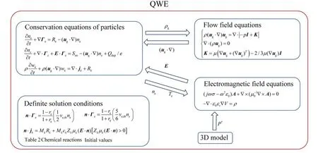
Figure 5.Multi-physical field equations.
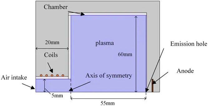
Figure 6.Schematic for observing the anode spot.
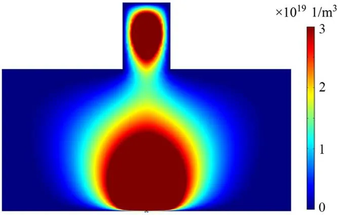
Figure 7.Map of the anode spot.
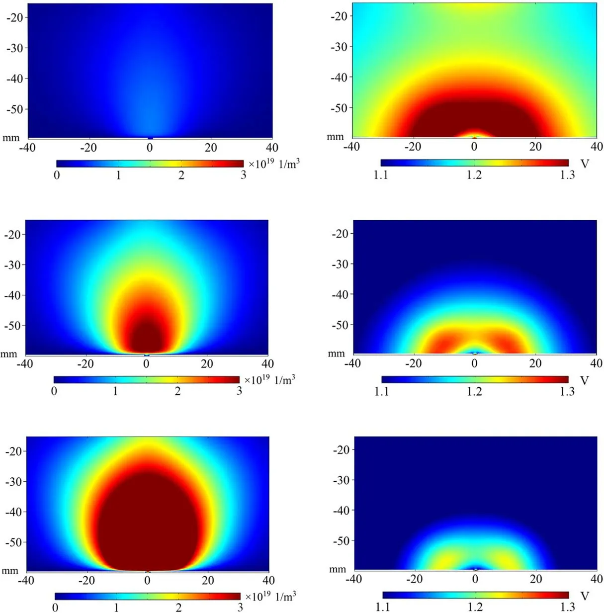
Figure 8. Electron density and electron temperature under different actuating gas flows.
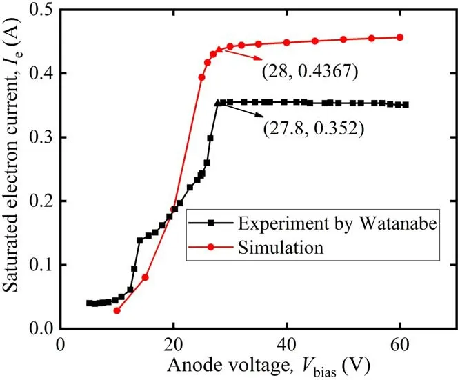
Figure 9.Experimental I-V characteristics versus calculated ones for a Xe RF inductive cathode.
Jahanbakhshet al[9]explored the influences of structural parameters on the electron current for an Ar RF inductive cathode.The collector area in his experiment is 30 cm2.When reproducing the experimental data,limited to two-dimensional form,it can only be realized by changing the length of the collector.According to the previous engineering practice,the collector is set close to the air inlet.As shown in figure 11,the simulation results are numerically comparable to the experimental ones,and the current jump region is also similar.
Figure 12 depicts the influence of actuating gas flow on the electron current,the electron number densityneand the electron temperatureTein Watanabe’s experiment.The electron number density and the electron temperature calculated by the model have the same trend as the experimental ones,but are lower in value,which can be seen from figure 12(a).The error is a result of the uneven distribution of the bulk plasma caused by the open cylinder collector,and the Langmuir probe used to measure the electron temperature and electron number density has a large unavoidable error.The trend of electron current with actuating gas flow in figure 12(b) exactly corresponds to the expansion of the anode spot in figure 8.However,on the whole,the model and experimental results have the same variation trend,and the numerical error is slight.
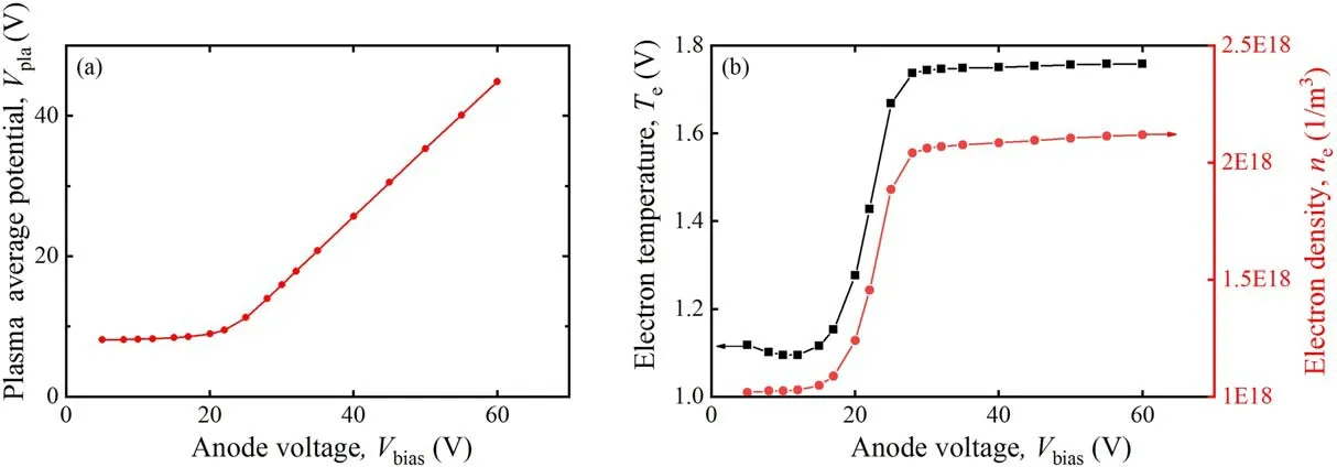
Figure 10.(a) Plasma average potential,(b) electron temperature and electron density with different bias voltages.
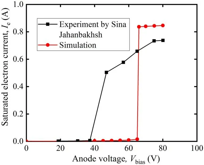
Figure 11.Experimental I-V characteristics versus calculated ones for an Ar RF inductive cathode.
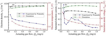
Figure 12.(a) Saturated electron current,saturated anode voltage,(b) electron production cost and actuating gas utilization with different actuating gas flows.
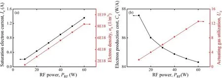
Figure 13.(a)Saturated electron current,electron density,(b)electron production cost and actuating gas utilization with different RF powers.
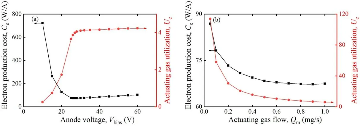
Figure 14.Electron production cost and actuating gas utilization with different preset discharge parameters.(a) Bias voltage,(b) actuating gas flow.
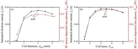
Figure 15.Saturated electron current and Pdep with different coil structures.(a) Coil diameter,(b) coil turns.
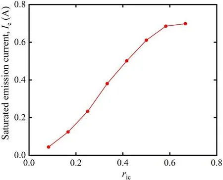
Figure 16.Saturated emission (electron) current versus differentr ic.
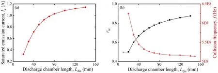
Figure 17.(a) Saturated electron current,(b)ric and collision frequency with different chamber lengths.
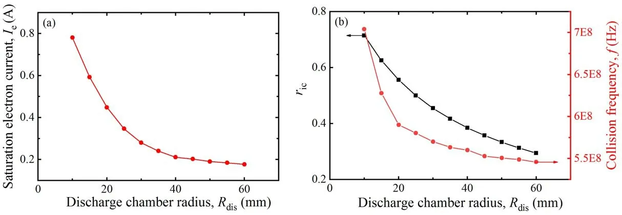
Figure 18.(a) Saturated electron current,(b)ric and collision frequency with different chamber radii.
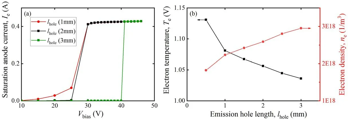
Figure 19.(a) I-V characteristics,(b) electron temperature and electron density with different hole lengths.
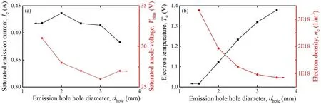
Figure 20.(a) Saturated electron current,saturated anode voltage,(b) electron temperature and electron density with different hole lengths.
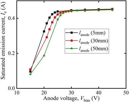
Figure 21.I-V characteristics with different distances between the anode target and the emission hole.
4.Influences of preset discharge parameters and cathode structural parameters on cathode performance
4.1.Influences of preset discharge parameters
The electron current increases linearly with RF power,as does the power consumption,as shown in figure 13(a).For the sake of clearly evaluating the influence of RF power on the cathode performance,this subsection uses the two parameters mentioned above,the actuating gas utilization and the electron production cost.The actuating gas utilization is defined as
It should be noted that 1 mg s-1of Xe can introduce an electron current of 71.8 mA.The electron production cost is
As shown in figure 13(b),as the RF power grows,the electron production cost decreases slightly,and the actuating gas utilization increases significantly.The influences of the bias voltage and the actuating gas flow on cathode performance have been explained in section 2.In this subsection the electron production cost and actuating gas utilization corresponding to figures 9 and 12 are taken into consideration.
With increasing bias voltage,the electron production cost first rapidly drops to a minimum value and then rises slowly,while the actuating gas utilization jumps to a high value at the beginning and then rises slowly,as indicated in figure 14(a).What is more,the abscissa of the two transition points corresponds to the saturated anode voltage.By approaching the saturated anode voltage,the bias voltage comes to its optimal preset value.In figure 14(b),it is shown that the electron production cost and the actuating gas utilization decrease at first and then become stable with the actuating gas flow.Therefore,the target electron current and the total gas reserve should also be considered when setting the optimal actuating gas flow.
4.2.Influences of structural parameters
When studying the impact of structural parameters on the performance of RF inductive cathode without changing the preset parameters,the variation trend of the actuating gas utilization is the same as that of the electron current,while the variation trend of electron production cost is opposite.Therefore,only the electron current is taken into account as the evaluation indicator of the anode performance.
4.2.1.RF coil.In this work,the coil is uniformly wound in spiral mode.Therefore,only the influences of the diameter and turns of the coil on cathode performance are considered.As mentioned above,the skin depth of RF current in the copper coil isμ17.94 m.The coil is solid in this work for the purpose of simplifying the mesh,although the performance of the RF inductive cathode is independent of whether the coil is hollow or solid.
The coil resistanceRcoiland the coil currentIcoilall affect the electron current by means of impacting the RF power deposited into plasma.Since the coil resistance decreases with increasing coil diameter while the coil current increases,there is at least one extremum forPdep:
As shown in figure 15(a),when the coil diameter is about 2 mm,Pdepcomes to an extremum,at which the electron current is the maximum.Therefore,the coil diameter should be 2 mm in this example.Similarly,figure 15(b) illuminates that the optimal number of turns of the coil is 5.
4.2.2.Discharge chamber size and ion collector area.In practice,the length of a cylinder ion collector with a slit on the side generally equals that of the discharge chamber.Thus,whenever changing the size of the discharge chamber,the area of the ion collector will also be altered,so the two are considered in one subsection.
When the RF inductive cathode operates stably,every time an ion is neutralized on the collector,an electron passes through the emission hole.However,ions also react with electrons on the quartz wall of the discharge chamber to form atoms,which prevents electrons from flowing out of the emission hole,leading to a decrease in electron current.For the sake of evaluating the effect of the collector area on the cathode performance comprehensively,a parameterric=Ai/Ae,the ratio of the collector area to the inner area of the discharge chamber,is introduced.
First,the impact of the ion collector area on the electron current is investigated by taking a discharge chamber with a length of 40 mm and radius of 20 mm as an instance.Restricted by two-dimensional form,the ion collector area can only be adjusted by changing its length.The stable saturated electron current grows in pace with the growth ofric,as indicated in figure 16.The tendency of the electron current in figure 16 is on account of the fact that more ions are‘absorbed’ on the surface of the ion collector,leading more electrons to flow out,but the current tends to be stable due to the plasma density limitation.
Moreover,it has been shown in fgiure 17(a) that the electron current rises with increasing discharge chamber length.As indicated in figure 17(b),the growth of discharge chamber length not only increasesric,which gives rise to the electron current,but also reduces the inelastic collision frequency,which contributes to the decrease in electron current.However,the electron current still shows an upward trend overall.
Similarly,figure 18(a) depicts the relationship between the discharge chamber radius and the saturated electron current,in which the electron current drops primarily and then stabilizes at 0.2 A.As shown in figure 18(b),the collision frequency decreases while the discharge chamber volume rises.It is deduced that under the same conditions,changes in the length or diameter of the discharge chamber hardly affect the chamber pressure but have an impact on the chamber volume,resulting in variation in the collision frequency.What is more,the saturated electron current goes down with the growth of chamber radius,because the growth rate of the ion collector area is lower than that of the chamber inner surface.
4.2.3.Size of the emission hole.Since the model is in a twodimensional axisymmetric form,the shape of the emission hole can only be set as a circle.Thus,this section only takes the size of the emission hole into consideration.The alteration of the emission hole size contributes to the variation in chamber pressure and thus affects the electron number density and electron temperature,and also interferes in the extraction efficiency of bias voltage.
As shown in figure 19(a),the growth of emission hole length hardly influences the saturated electron current but boosts the saturated anode voltage.The increase in emission hole length increases the pressure in the discharge chamber,inducing an increase in electron number density and a decrease in electron temperature,which can be clearly seen in figure 19(b).However,as the actuating gas flow is 1.5 mg s-1,the pressure in the chamber is high enough to provide sufficiently dense plasma even if the hole length is 0.5 mm.Hence,the saturated electron current at this time is not affected by the pressure but by the RF power.Moreover,the reduction of electron temperature near the emission hole requires a higher bias voltage to make electrons gain the energy to ionize neutral particles,resulting in a rise in saturated anode voltage.
Under the same operating conditions,an enlargement of emission hole diameter decreases the pressure in the discharge chamber,which generates a decrease in electron number density and an increase in electron temperature,as depicted in figure 20(b).Corresponding to figure 19(b),the increase in electron temperature enables the formation of anode spots at a lower bias voltage.However,when the hole diameter increases to 3 mm,the plasma density is still too low,even though the electron temperature rises continuously with the hole diameter,demanding a higher bias voltage to form the anode spots.Therefore,the saturated anode voltage first decreases and then increases with the hole diameter in figure 20(a).When the hole diameter is 2 mm,the plasma density is relatively high.A reduction in the hole diameter decreases the electron temperature and weakens the extraction effect of the bias voltage,resulting in a reduction in the emission current.Thus,the hole diameter of 2 mm in figure 20(a)corresponds to the highest electron current.
4.2.4.Distance between anode target and emission hole.A bias voltage source connected to the anode target provides an electric field force to extract electrons.It can be seen from figure 21 that the distance between the anode target and the emission hole does not affect the magnitude of the saturated electron current,but the shorter the distance,the lower the saturated anode voltage.In line with the illustration in section 2,the saturated anode voltage does not drop to zero but tends to a stable value.In this configuration,the minimum saturated anode voltage is about 20 V.
5.Conclusion
A two-dimensional RF inductive cathode numerical model is developed,in which all the RF electromagnetic field,electrostatic field for extracting electrons,flow field,plasma transport and electrochemical reaction process are accounted for.This model is verified by comparing the predicted results with those of the non-bipolar flow theory on the formation process of the anode spot,and with the experimental data collected by Watanabe and Jahanbakhsh,which demonstrates that the current jump in RF inductive cathode is caused by the anode spot.By means of comparing electron current,electron production cost and actuating gas utilization,the first-rank preset of RF power,bias voltage and actuating gas flow can be selected.Moreover,this model is beneficial for figuring out the impact of structure parameters on cathode performance.First,by comparing the RF power deposited into the plasma,it is found that the optical diameter and number of turns of the coil should be 2 mm and 5,respectively.Furthermore,the ratio of the collector area to the inner area of the discharge chamber is proposed to analyze the influence of the ion collector area on the electron current,and the stable saturated electron current grows in pace with the ratio of the collector area to the inner area from 0 to 0.8.In addition,the simulation results indicate that the saturated electron current goes down with the growth of chamber radius and increases with the growth of chamber length.Specifically,the optimum structural parameters of the emission hole are 0.5 mm in length and 2 mm in diameter.Moreover,the distance between the anode target and the emission hole hardly affects the magnitude of the saturated electron current,but influences the saturated anode voltage.In the near future,it is expected that a better RF inductive cathode with high quality,low cost,and highly practical electron production efficiency will be developed based on this model.
猜你喜歡
炎黃地理(2024年6期)2024-01-01 00:00:00
東坡赤壁詩詞(2020年3期)2020-07-04 02:50:05
書香兩岸(2020年3期)2020-06-29 12:33:45
中國篆刻(2018年12期)2018-12-26 01:10:30
金沙江文藝(2018年3期)2018-04-20 01:53:38
民間故事選刊·上(2017年4期)2017-04-07 15:40:52
語文世界(小學版)(2017年2期)2017-03-15 08:41:37
語文世界(小學版)(2016年12期)2017-01-05 13:23:35
青少年科技博覽(中學版)(2016年2期)2016-06-01 02:03:16
小小說月刊·下半月(2016年8期)2016-05-14 15:23:25
 Plasma Science and Technology2023年2期
- Plasma Science and Technology的其它文章
- Square grid pattern with direction-selective surface discharges in dielectric barrier discharge
- Magneto-hydrodynamic simulation study of direct current multi-contact circuit breaker for equalizing breaking arc
- Oxidation of ciprofloxacin by the synergistic effect of DBD plasma and persulfate:reactive species and influencing factors analysis
- Experimental and numerical investigation of a self-supplementing dual-cavity plasma synthetic jet actuator
- Investigation of cyclohexane catalytic degradation driven by N atoms from N2 discharges
- Self-absorption effects of laser-induced breakdown spectroscopy under different gases and gas pressures