
Cell-type continuous electromagnetic radiation system generating millimeter waves for active denial system applications
2022-10-17 03:46:00SunHonMnOjoonKwonMtlbjonSttorovSeonteKmInKeunBekSeunyukPrkRnjnKumrBrkAnrbnBerDonpyoHonSeonmyeonKmBonHwnHonCwonPrkSukwlMnoKmKyoCulLeeYonJnLeeHnByulKwonYounJoonYooSnYoonPrkGunSkPrk
Defence Technology 2022年10期
Sun-Hon Mn ,Ojoon Kwon ,Mtlbjon Sttorov ,Seonte Km ,In-Keun Bek ,Seunyuk Prk ,Rnjn Kumr Brk ,Anrbn Ber ,Donpyo Hon ,Seonmyeon Km ,Bon Hwn Hon ,Cwon Prk ,Sukwl M ,Mno Km ,Kyo Cul Lee ,Yon Jn Lee ,Hn Byul Kwon ,Youn Joon Yoo ,Sn Yoon Prk ,Gun-Sk Prk ,*
a Korea Institute of Radiological and Medical Sciences (KIRAMS),Seoul,01812,South Korea
b Institute for Basic Science,Center for Axion and Precision Physics Research,Daejeon,34141,South Korea
c Center for THz-Driven Biomedical Systems,Department of Physics and Astronomy,College of Natural Sciences,Seoul National University,Seoul,08826,South Korea
d Center for Applied Electromagnetic Research,Advanced Institute of Convergence Technology,Suwon,Gyeonggi-do,16229,South Korea
e R&D Department,Seoul-Teracom,Inc.,Suwon,16229,South Korea
f Mechatronics R&D Center,Samsung Electronics Co.,Ltd.,Hwasung,18448,South Korea
g Hanwha Corporation,Gumi,730-030,South Korea
h Council of Scientific and Industrial Research,Central Electronics Engineering Research Institute,Pilani,333031,India
i Home Economics Education/Biosystems and Biomedical Sciences,Korea University,Seoul,02841,South Korea
Keywords:Millimeter waves Terahertz waves Coupled-cavity backward wave oscillator(CCBWO)Cell-type continuous electromagnetic radiation Active denial system (ADS)Directed-energy weapon (DEW)
ABSTRACT The cell-type continuous electromagnetic radiation system is a demonstration device capable of generating high-power millimeter electromagnetic waves of a specific wavelength and observing their effects on living organisms.It irradiates a biological sample placed in a 30 × 30 × 50 cm3 cell with electromagnetic waves in the 3.15-mm-wavelength region (with an output of ≥1 W) and analyzes the temperature change of the sample.A vacuum electronic device-based coupled-cavity backward-wave oscillator converts the electron energy of the electron beam into radiofrequency (RF) energy and radiates it to the target through an antenna,increasing the temperature through the absorption of RF energy in the skin.The system causes pain and ultimately reduces combat power.A cell-type continuous electromagnetic radiation system consisting of four parts-an electromagnetic-wave generator,a highvoltage power supply,a test cell,and a system controller-generates an RF signal of ≥1 W in a continuous waveform at a 95-GHz center frequency,as well as a chemical solution with a dielectric constant similar to that of the skin of a living organism.An increase of 5 °C lasting approximately 10 s was confirmed through an experiment.
1.Introduction
In the field of defense for the past 10 years,the development of nonlethal weapons is rapidly progressing and is an open secret between countries.Here,a nonlethal weapon is defined as a weapon that protects innocent citizens and minimizes damage to property and the environment while minimizing lethality.The US Department of Defense (DoD) guidelines define a nonlethal weapon as “a weapon designed to incapacitate persons or materials,to minimize fatal or permanent injury to the human body,and to avoid unnecessary damage to property and the environment.”Nonlethal weapons that temporarily disable the enemy's physical functions and destroy core functions without completely destroying facilities or equipment are classified for people and things and range from light or sound to weapons using millimeter (mm)waves,lasers,chemicals,and bacteria.There are many different types.The weapon category here refers to second-generation nonlethal technologies and applied weapons using sound,laser,and electromagnetic technologies,including basic nonlethal weapons such as tear gas and stuns.In particular,the US,which is proving the effectiveness of nonlethal weapons while conducting peacekeeping missions around the world,is developing nonlethal technology.The US military developed a heat-ray launcher with a range of 500 m called the Active Denial System (ADS) in the early 2010s and is currently using it.This weapon,which is shaped as a radar-like square launchpad and sits atop the Humvee-a US military vehicle-causes mild pain and is not life-threatening.In the case of a crowd riot,the weapon can be directed at protesters,causing them pain in their skin.The prevailing opinion is that it is more effective than rubber bullets.The heat rays can penetrate clothes and reach the skin,and the temperature increases to 50C instantly.Although the rays cause instant discomfort (a stinging feeling),they do not damage the skin.A similar weapon called“Silent Guardian” is being developed by the US military company Raytheon.This weapon rotates 360and shoots mm-wave heat rays at a crowd.The rays can travel up to 500 m and penetrate approximately 0.4 mm of the skin,stimulating the skin nerves and causing pain [1-10].
Most ADSs use a gyrotron-a high-power mm-wave vacuum device.In such ADSs,mm-wavelength energy is used to heat the skin surface,causing opponents/enemies/protesting crowds to instinctively flee.The waves generated by the gyrotron are weaker than microwaves.It is currently being considered for installation on tanks and other land vehicles,as well as on ships and aircraft.As part of the DoD's Joint Nonlethal Weapons Program,the DOD has invested more than a decade in the research,development,and testing of nonlethal weapons based on gyrotron energy that converts electricity into mm waves.It was reported that “The current model is ready for deployment to the military,and we plan to continuously improve the design.” Reducing the size and weight and moving to a high-temperature superconductor are challenges to be solved in the future.The gyrotron needs a superconducting magnetic field,because the energy beam is generated only in a strong magnetic field.The gyrotron itself is a powerful electron tube,which accelerates electrons through the cyclotron motion generated by the magnetic field.The accelerated voltage can be repeatedly applied to achieve relativistic speeds(near the speed of light).The DOD's gyrotron is manufactured by Communications &Power Industries(Palo Alto,California).The emergence of directedenergy weapons (DEWs),which will be the revolutionary weapon of war of the future,is already being realized.These include Nuclear magnetic resonance with signal enhancement through dynamic nuclear polarization,electron spin resonance spectroscopy,precision spectroscopy for hyper-fine structure measurements of positronium (Ps),etc.).Other major applications include material processing (e.g.,heat treatment and advanced ceramic sintering),remote sensing of concealed radioactive materials,radar,and biological and medical research.Future and emerging applications utilizing gyrotrons as radiation sources include imaging and sensing for inspection and control in a variety of technological processes (e.g.,food production and security).The Far-Infrared Region (FIR) Research Center at Fukui University in Japan is conducting research on positronium generation and imaging using a high-power millimeter-wave generator of a gyrotron vacuum device.Since it has a value,it has an intrinsic top spin direction;thus,it is difficult to emit photons owing to changes in gamma rays[18-22].
Free electron lasers,which are being studied in the Republic of Korea,and new energy beams operating in the terahertz range,ultrahigh-frequency range,etc.are still being used for developing outdated weapons owing to the lack of awareness of the authorities regarding the utility of these weapons.I think the time has come to prioritize high-efficiency beam weapons.Beam weapons,which appear in various forms,such as lasers,super-strong microwaves,and particle beams,can be used in various ways in land,air,naval,and even space warfare,depending on the electromagnetic environment and political and financial conditions.As reported in “Ebombs: How America's DEW Changes Future Warfare,” the US has been working on DEWs for the past 20 years and will soon deploy the next generation of DEWs.These weapons include aircraftmounted lasers,microwave-based nonlethal ADSs,and tactical high-energy lasers (THELs).The THEL,which uses a deuterium fluoride laser,has already proven its ability to heat high-altitude rocket warheads to self-detonate in desert experiments,and the mobile THEL can detonate multiple mortar shells simultaneously.The ADS,which is being developed with the support of the Marines,uses mm-wave electromagnetic energy to block approaching enemies,causing them to flee by inflicting extreme pain due to heating of their skin [23-29].
The continuous electromagnetic radiation generator based on the coupled-cavity backward-wave oscillator(CCBWO)of a vacuum electronic device (VED)manufactured in this study will ultimately know the effect of the continuous electromagnetic radiation generator in the terahertz range for the development of nonlethal weapon technology,especially on the human body(skin)[30-34].In particular,radiation devices with mm and sub-mm frequency bands are receiving considerable attention for applications,e.g.,medical devices,nondestructive diagnostics,remote control,search devices,high-speed wireless communication,astronomy,and biology.However,despite these diverse academic and technological interests and applications,this frequency band remains an unexplored area between the microwave and optical bands,which have been traditionally studied.The frequency band targeted in this study can be considered an early stage of an unexplored field.This band has been studied for various applications,but the scope of application research is limited owing to the absence of an efficient radiation device.Therefore,the development of such a device(targeted in this proposal) will have an extensive ripple effect on other fields of study and application,and by preempting a differentiated and unique technology in the terahertz band that has already started or will be actively used in the near future,it is also expected to have an important meaning in value and to have a potential ripple effect.
2.Millimeter waves source: coupled-cavity backward wave oscillator (CCBWO)
2.1.Circuit composition and operation principle
The CCBWO circuit consists of a cavity where strong fields and energy are stored,a gap where the electron beam and the field interact,a beam tunnel that is a passage for the electron beam,and a coupler that radiates the generated RF energy to the waveguide.The operating principle is as follows.As shown in Fig.1,when an electron beam is incident in the direction of the arrow and passes through the beam tunnel,a field is formed in the internal circuit by the beam with high energy.The generated electric field presents the effect of a slow wave structure based on a periodic structure and bunches the electron beam.The kinetic energy of electrons is converted into RF energy by the interaction of the bunched electron beam and the circuit,and RF energy is output through the coupler.To further explain Fig.1,the principle of the CCBWO circuit is similar to that of the folded waveguide,and electromagnetic waves in the basic TEmode propagate along the curved path.At this time,the curved path becomes a slow wave and interacts with the electron beam.In the gap,the phase changes periodically to stimulate electron-beam bunching.This makes it possible to generate a continuous high output power via a strong interaction using multiple coupled cavities in the context of a simple radiation mechanism.

Fig.1.Structure of CCBWO (top) and tunnel beam-wave interaction (bottom).
The structure shown in Fig.1 functions as a slow-wave structure,connecting cavities with the same resonant frequency.The electron beam traveling through this structure interacts with RF waves polarized in the same direction as the traveling direction of the electron beam formed in the beam tunnel.An electron beam with energy of 12 kV is designed to satisfy the dispersion of the circuit,at 5π/2 of 0.1 THz.As a result,the cycle of the synthesized circuit is 0.8 mm,the radius of the beam tunnel is 0.28 mm,and the dimension of the smallest structure is 0.2 mm.The designed circuit and electron beam were confirmed to meet in the vicinity of 5π/2 at 0.1 THz.
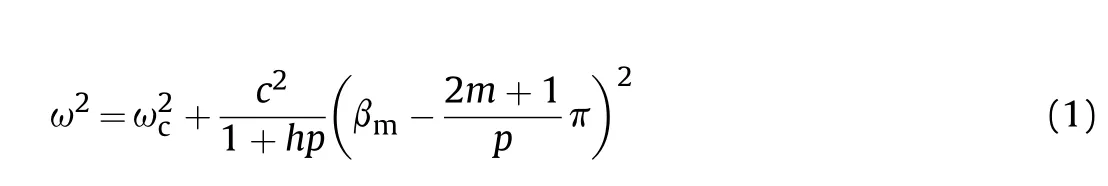
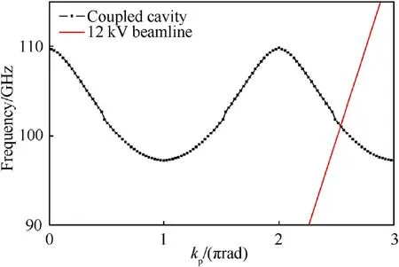
Fig.2.Dispersion relation of CCBWO Circuit.
The dispersion relationship of the CCBWO structure having a periodic structure considering the interaction of the TEmode is given by Eq.(1).Here,ωrepresents the cutoff frequency,p represents the period,and h represents the maximum distance between cavities facing the beam tunnel [35].The distribution relationship of Eq.(1) is expressed as a graph in Fig.2,the dotted black line indicates the dispersion relationship of the CCBWO.The graph is periodic with shifted structural characteristics.RF energy may be radiated through the coupling at the point where it meets the beamline indicated in red line.For backward interaction,coupling must occur in the region where dω/dκ becomes negative.Considering the electron beam within 15 kV in the requirement of a compact source,the region can be determined at the secondharmonic point.Thus,considering the phase,it is possible to form a backward wave of the second harmonic only when coupling occurs in the phase region of 2π to 3π.Dimensional information related to beam tunneling and cavity is shown in Table 1.
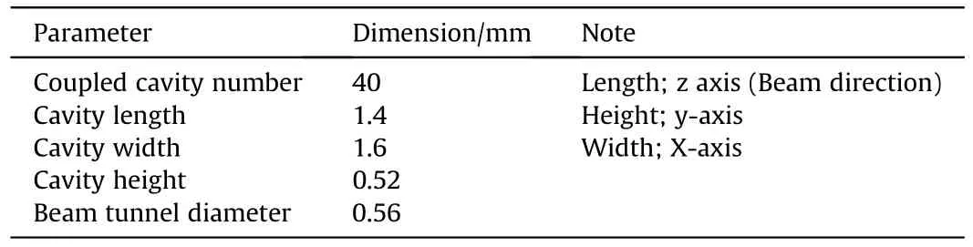
Table 1 The dimensions for the coupled cavity.
2.2.Optimized CCBWO: fabrication and specification
In general,the electron beam emitted from the electron gun spreads as it progresses under the space charge force.To keep the cross-section of the electron beam constant until the end of the circuit without such spreading,an appropriate magnetic field is required according to the current and minimum radius of the electron beam.In this study,a permanent magnet made of neodymium was used to achieve the following compact system.The design of the magnetic field for focusing the electron beam is a part of the electron-gun manufacturing,and it can be considered as an important part that connects the electron gun and RF circuit.Fig.3 shows the overall structure of the manufactured continuous radiation device(CCBWO).First,an electron gun generates an electron beam.The electron gun is composed of a shield part that controls the effect on the electron beam from a magnetic field,a permanent magnet,a coupled cavity circuit,a coupler,and a beam depressed collector.The electron gun is designed and manufactured by determining the voltage,current,etc.of the electron beam suitable for the output of the given electromagnetic wave.The CCBWO circuit was fabricated via DRIE and two-step X-ray LIGA processes.
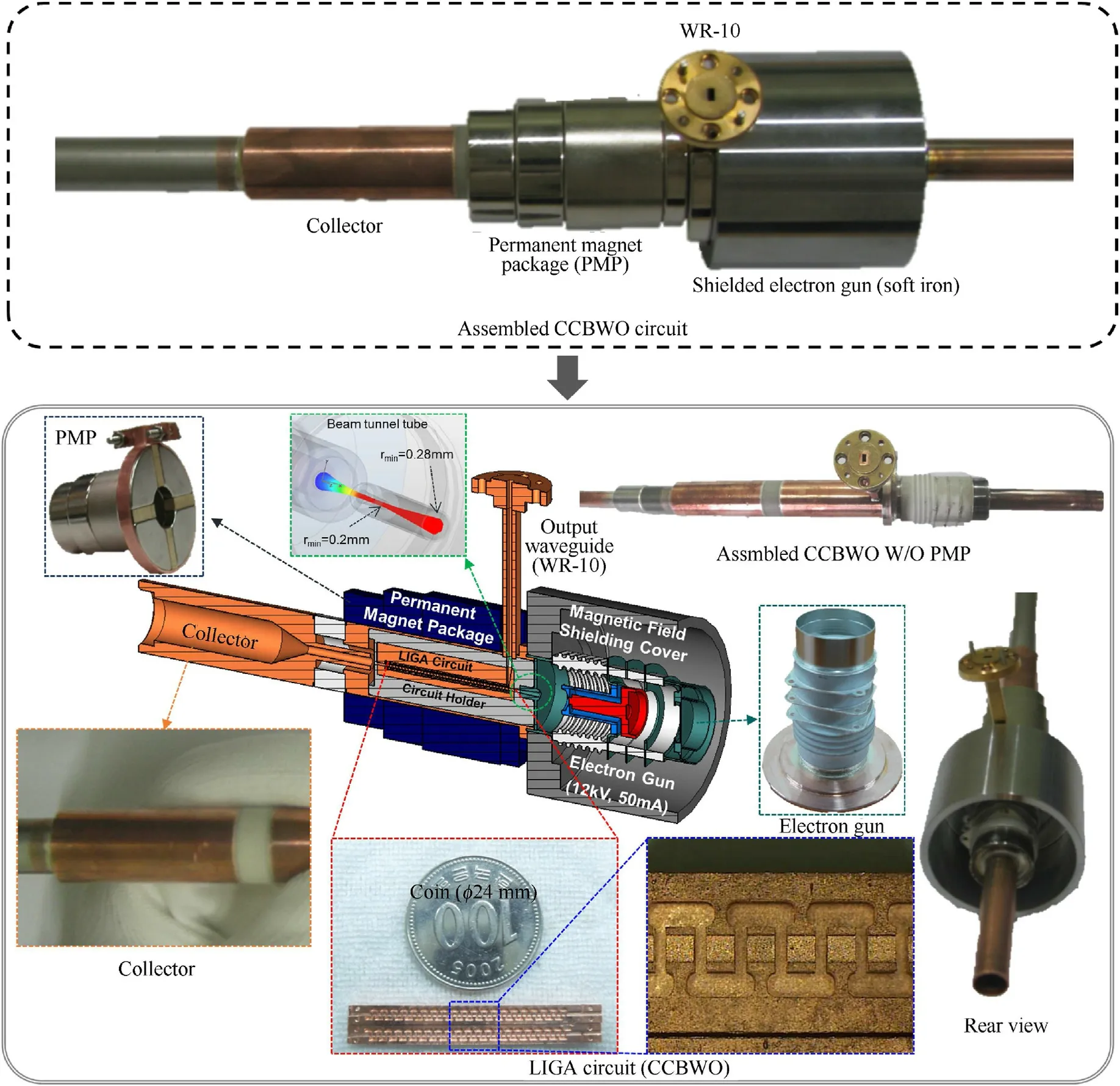
Fig.3.Fabricated CCBWO circuit.
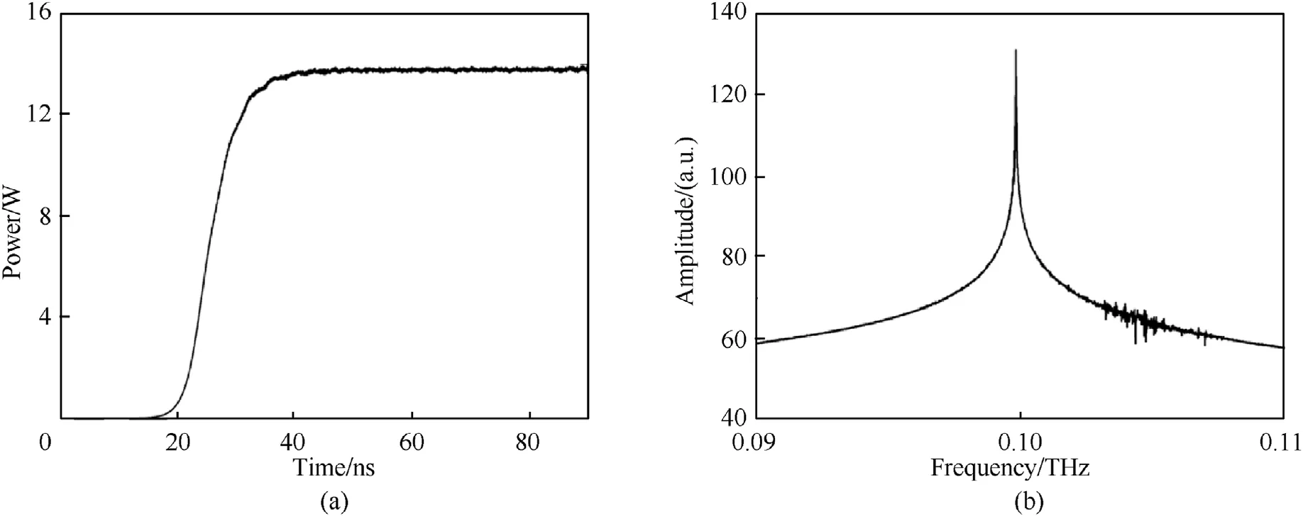
Fig.4.Characteristics from beam-wave interaction under 12 kV -50 mA;(a) RF power,(b) frequency [38].
The circuit adopted for RF oscillation extracts RF energy from the inlet of the circuit.To minimize the loss of the generated RF energy,it is extracted from the front part of the circuit,as shown in the following figure.Because of the output waveguide,permanent magnets entering this position cannot be of the symmetrical ring type;thus,four segment-type magnets are used instead.Finally,as shown in the figure below,a permanent magnet system consisting of four segment-type magnets and four ring-type magnets was designed (PMP in Fig.4).The axial magnetic-field distribution of individual magnets was examined,and a magnetic field that could be focused was created through their combination (Fig.4).It was confirmed that an electron beam of 12 kV and 50 mA proceeds within such a magnetic field while maintaining a beam radius of 0.18 mm to the end of the circuit.For an effective interaction between the electron beam and the circuit,the axial velocity of each electron in the electron beam must be uniform.Additionally,it was confirmed that the axial velocity spread of the electron beam was kept below 0.1%until the end of the circuit.The axial velocity of all the electrons is then the same as that of an electron on the axis.When the beam is not in Brillouin flow(>1)the angular velocity is smaller and the axial velocity of the electrons varies with radius.This means that there is almost no axial velocity spread for the electron beam at the resonance frequency of 95 GHz,which is the dominant mode of oscillation,when m is 1.For the case of=2,the angular velocity is only 13% of the Brillouin value,and the change in axial velocity is almost entirely determined by the change in potential.For the calculation of axial velocities,these corrections can be small,especially important when modeling a traveling wave tube (TWT) like CCBWO.The reason is that the center frequency is particularly sensitive to changes in electron velocity.In many cases,it is sufficient to use the electron velocity of the axis as an approximation of the average axial velocity of the electron beam[34,36].When an electron beam of 12 kV and 50 mA was used,as shown in Fig.4,an RF output of approximately 14 W was generated in the vicinity of 0.1 THz (actually 95 GHz).According to the change in the current value of the electron beam,the circuit started oscillating at approximately 25 mA.
While the electron beams pass through the beam tunnel,the electrons gradually gather periodically,and the accumulated beams again become unfastened at the end of the beam tunnel.The beams’ energy is distributed by approximately 5% in a bunched beam.The expected output power at 0.1 THz is >13.5 W.The coupled cavities strengthen the interaction between the gap field and the electrons.
3.Cell-type continuous electromagnetic wave radiation system
3.1.System operation and performance
The cell-type continuous electromagnetic wave radiation system is a demonstration device that can generate high-power subterahertz electromagnetic waves of a specific wavelength and observe their effects on living things.This system emits electromagnetic waves in the 3.15 mm wavelength region with an output of ≥1 W,irradiates biological samples placed in 30×30×50 cmcells,and analyzes the temperature change.The operating concept of the cell-type continuous radiation device is shown in Fig.5.The electron energy of the electron beam is converted into RF energy by the VED-type electromagnetic-wave source and radiated to the target through the antenna.The temperature rise resulting from the absorption of RF energy in the skin causes pain and degrades the combat power.
Table 2 presents the main performance of the cell-type continuous electromagnetic wave radiation system.
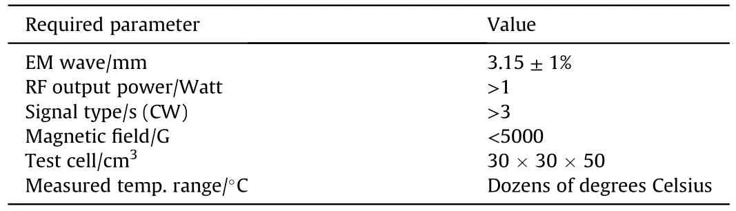
Table 2 Required specifications of the cell-type continuous electromagnetic wave radiation system.
The cell-type continuous electromagnetic wave radiation system can be divided into four parts according to their functions,as shown in Fig.5:the electromagnetic-wave generator,high-voltage power supply (HV-PS),test cell,and system controller.In the HVPS,when a high potential difference of DC is applied to the electron gun,the electron beam from the electron gun is focused by a focusing device such as a magnet and enters the RF circuit to form continuous RF energy through interaction.The formed RF energy is radiated to the target through an appropriate antenna,and signals are extracted from it.The frequency and power are monitored.The temperature change of the target due to the high RF output is measured using an infrared(IR)camera and monitored in real time through the computer system.Therefore,basic research on whether the cell-type continuous electromagnetic wave emitting device can inflict appropriate pain on living things will be conducted.The electromagnetic-wave generator and HV-PS are dependent on each other and can be manufactured as a single subterahertz source separately.The test cell is a device that solves the test site and method of a high-output sub-terahertz source,only the frequency characteristics of the source This is dependent on Subordinate to all of this is the system controller.
3.2.Design,manufacture,and assembly of cell-type continuous electromagnetic wave generation system
The Based on Figs.5 and 6 presents a configuration diagram of the cell-type continuous electromagnetic wave experimental system after the overall device design is completed.Considering the function of each device,the actual specifications of each component were limited,and the overall system arrangement was configured as shown in Fig.6.In one rack,components that require a high voltage to generate electromagnetic waves,such as an electromagnetic-wave generator and voltage supply,a diagnostic device for diagnosing the generated RF signal,and a test cell for examining the radiation effect were designed in a one-piece(all-inone) system.
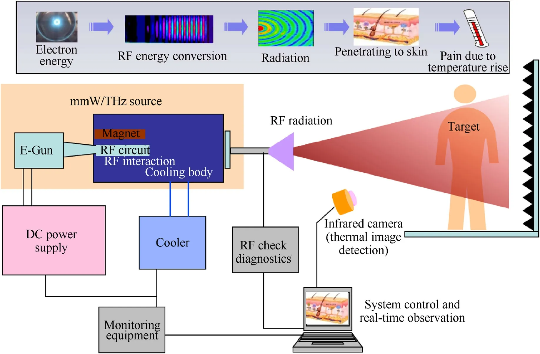
Fig.5.Conceptual outline of the cell-type continuous electromagnetic wave radiation system.
The CCBWO was installed inside the electromagnetic mm-wave(EM mmW) source,as shown in Fig.6(b) and (c).Most of the heat comes from the depressed collector (300 W of thermal energy is expected).The maximum expected temperature is <80C.The aircooled cooler is an efficient cooling system,and a typical commercial fan with an outer diameter of 80 mm can be used.Therefore,the depressed collector and air-cooled cooler are combined,a cooler auxiliary that surrounds the depressed collector is installed,and a cooling fan-type air-cooled cooler is installed together with a heat sink to achieve efficient cooling.The case of the EM mmW source is manufactured with consideration of the high voltage,protection of the system from external impacts,and the RF output.Although the EM mmW source has a core device in the middle,it is relatively light compared with both sides and is easy to bend;thus,it must be supported with an appropriate mount.Keep a close distance,and because different high voltages are in contact with the electron gun,proper isolation must be made.It was designed to support only the parts corresponding to the ground,so that proper isolation of the electromagnetic-wave source is possible.In addition to this basic case,an external case for the purpose of deviceization was added to port an HV-PS,heater power supply,and highvoltage connection.
As shown in Fig.6,the heater power supply(HV-PS),and power divider are arranged in that order from the top.Each unit is designed to be mounted in a 19standard rack,and the total unit height is approximately 7U (approximately 32 cm).The estimated weight of the unit is 10 kg.
Fig.7 presents the detailed design of the small chamber to be mounted inside the test cell,which is shown in Fig.6.The design value of the chamber was determined according to the data analyzed in advance for the effect of the reflected wave,and the dimensions are presented in Table 3.The thickness of the acrylic was determined to be 5 mm.Acrylic of this thickness is manufactured often because the influence of the reflected wave does not change significantly with respect to the manufacturing error.It is planned to be manufactured in a zigzag structure so that the height of the positioner can be adjusted by 300 mm.The positioner shown in the figure is used when adjusting the height.
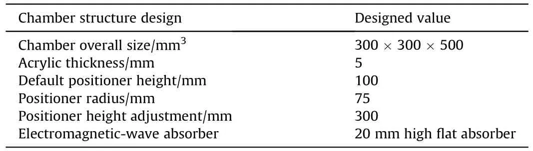
Table 3 Detailed design of the small chamber.
For the shape design of the RF diagnostics,the rack of the diagnostic device was configured as shown in Fig.8(a).A general PC power supply that supplies 12 V/5 V power is used.An 8-V regulator keeps the frequency of the local oscillator (LO) constant through the stable power supply.The WR-10 standard terminal that can receive the signal from the electromagnetic-wave source is set as an external port.A cooling fan is installed outside to prevent excessive heat generation.The adjustment screws of the LO and attenuator are installed so that they can be adjusted from outside the rack.
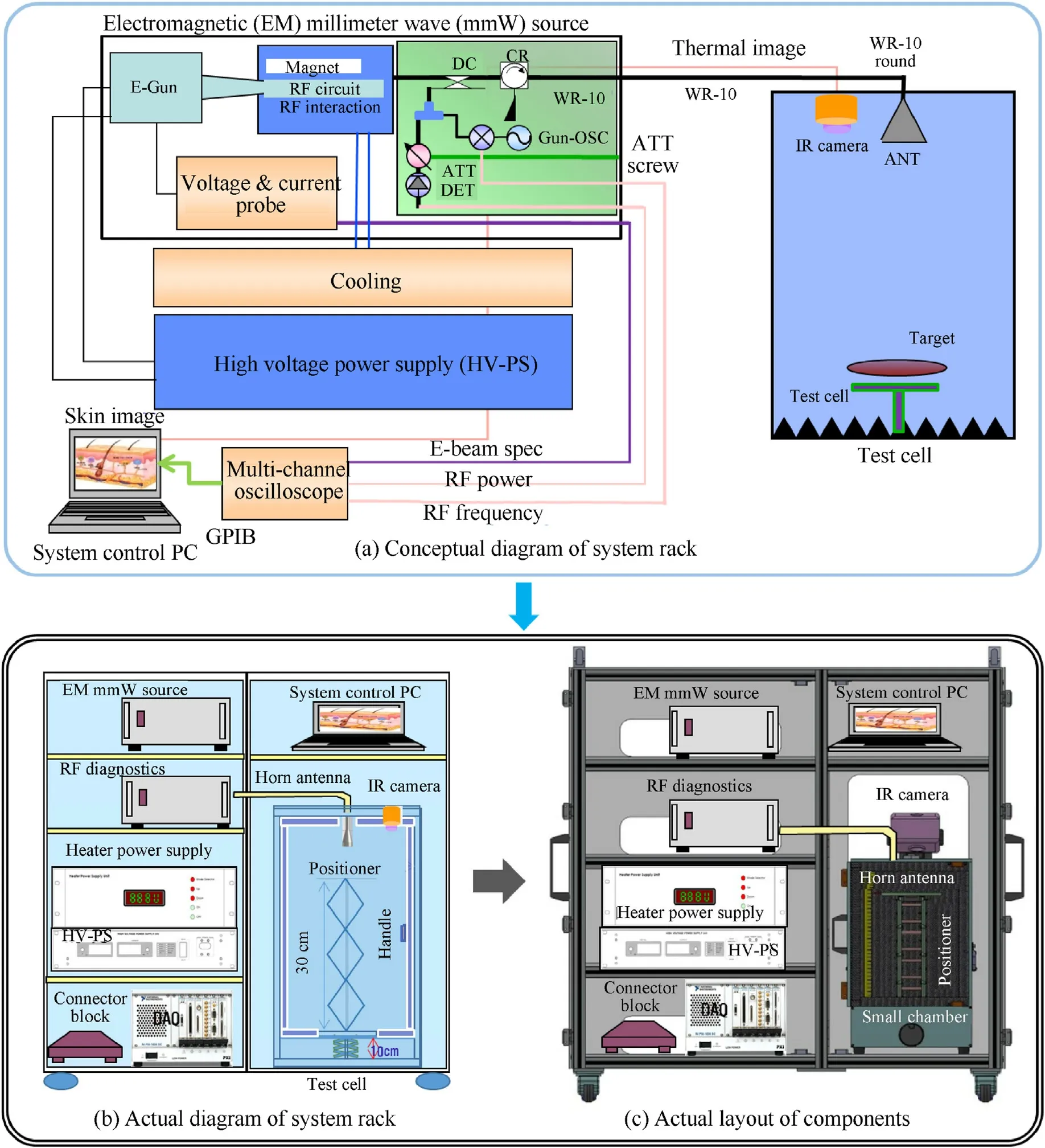
Fig.6.From conceptual design to actual design: cell-type continuous electromagnetic wave radiation system.
The cell-type continuous electromagnetic wave radiation system radiates the CW signal generated by the power supply through the horn antenna.It is necessary to design an antenna that can satisfy the power-supply standard determined above or to use an existing antenna that satisfies the conditions.The cell-type continuous electromagnetic wave radiation device is not intended to be used in practice but to emit electromagnetic waves toward an object and observe the resulting temperature change.In contrast to the system used in practice,it does not require a high-gain antenna;rather,a circular horn antenna is used.The antenna was prepared with internationally compatible specifications,as shown in Fig.9(a)and(b).The proposed horn antenna has a gain of 22 dBi and a halfpower beam width of 14.3.For the actual chamber design,the performance of the antenna to be used in the chamber must be known to allow the prediction of the specifications and performance of the purchased horn antenna.
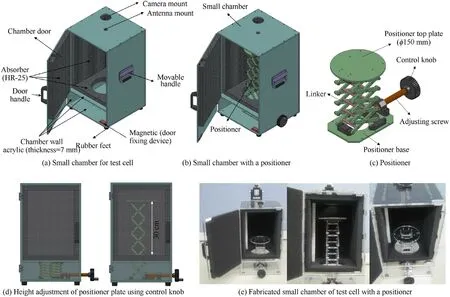
Fig.7.Detailed design and three-dimensional (3D) modeling of the small chamber.
The simulation results for the antenna and the calculation results obtained through the horn antenna electric-field analysis are presented in Table 4.As shown,the theoretical values and the simulation results are similar overall,except that the E-plane results of the half-power beam width and the phase center do not match well.The slight difference from the calculation result is attributed to the existence of a structure in the simulation.By analyzing the pattern of the antenna,it was confirmed that the Eplane-20.27 dB and H-plane-23.57 dB at approximately 21,the smallest angle that the electromagnetic wave radiated from the antenna can be reflected from the wall of the chamber.In the end,because the other reflected waves are larger than the incident angle at this time,it can be said that the effect of the reflected wave at 21has the greatest effect on the target.By substituting this result into the reflected-wave analysis result that does not consider the antenna pattern,the effect of the reflected wave when an actual antenna is present was considered.Considering the antenna pattern,it was confirmed that the direct path standard -25.2 dB is output when the reflected wave has the greatest effect,which is approximately 0.3% of the direct wave power.Therefore,the effect of the reflected wave is insignificant compared with that of the direct wave.
The material of the chamber case used in the experiment was acrylic.At low frequencies,acrylic has a relative permittivity of approximately 3-4 and a relative permeability of approximately 1,making it a nonmagnetic material.However,investigating the physical properties of acrylic in the W-band region (70-110 GHz)revealed that the relative permittivity was approximately 2.618,which differs from the generally known value [39,40].To confirm the effectiveness of the cell-type continuous electromagnetic wave radiation system,its performance should be tested using a material having properties similar to those of human skin.To this end,when the continuous electromagnetic wave generated by the power supply is radiated inside the chamber through the horn antenna,it is necessary to measure the temperature change of the skin sample by placing it in the direction of the horn antenna and operating the device.Therefore,it is necessary to check the electrical properties,such as the dielectric constant,magnetic permeability,and conductivity,of the skin sample to be used,as well as properties such as the specific heat.Human cellular tissue generally has a conductivity of approximately 0.2-0.7 S/m.Additionally,because it is not a magnetic material,its relative permeability is expected to be approximately 1.However,examining the physical properties of the skin in the W-band region revealed significant differences from the generally known properties,as shown in Table 5.
Regarding the system case frame design,the rack size was 640 × 1240 × 1065 mmas the outer standard.The outer wall of the rack was made of transparent acrylic (thickness of 5 mm).The shelf was also made of transparent acrylic(thickness of 8 mm).The weight of the rack was 75 kg(±10%).As for the casters,the wheels of a general rack were attached near the four vertices of the floor to enhance the portability.On the back side,a rear auxiliary box made of aluminum was installed,as shown in Fig.10,to organize the power connection lines.At this time,it is designed to be grounded(see Fig.11).
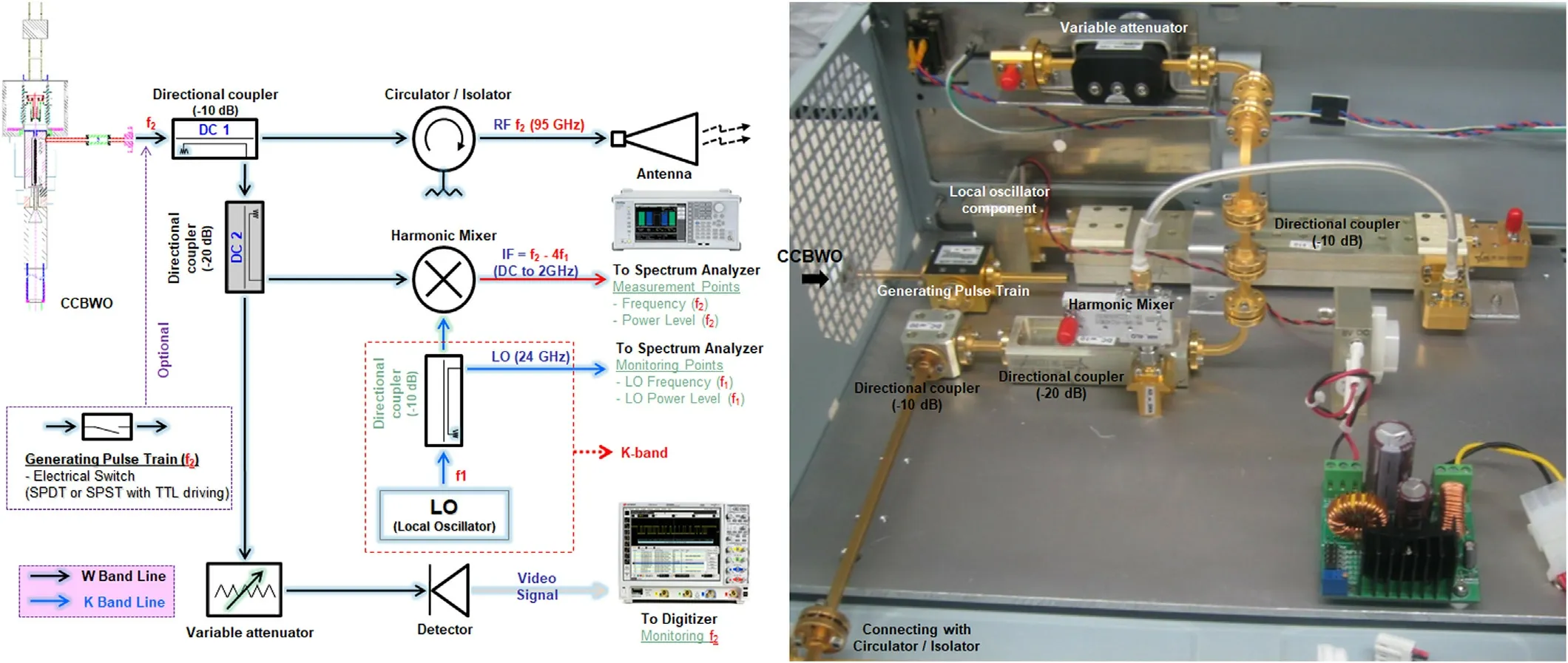
Fig.8.RF diagnostics;DC 1 divides into main output and diagnostic output.(The signal is divided by-10 dB and the output of 0.9 W(~29 dBm)is passed,and the signal of 20 dBm is divided to the diagnosis unit.)DC 2 divides the signal into the output diagnosis unit and the frequency diagnosis unit and transmits the signal.(In-20 dB,the main is sent to the output diagnosis unit,and the signal of 0 dBm is transmitted to the frequency diagnosis unit.) The Harmonic Mixer mixes the LO signal and the signal from the electromagnetic wave source.(Using Harmonic 4 times multiplier,K band signal can be used as LO.IF signal is transmitted under 100 MHz)LO uses K-band source to transmit signal to Mixer.(Use a mechanically tunable source of 24-25 GHz for signals of 94-96 GHz.Digitizer is an oscilloscope that analyzes frequency signals and output signals.(This oscilloscope must be able to read the frequency of 100 MHz IF signals;250 mega samples/sec).
4.Experimental results
4.1.Performance of EM mmW source based on the CCBWO with HVPS
In the experiment,as the VED-based CCBWO,the given frequency and output were tested,and the performance of each component was also tested.In the diagnostics section,for oscillation of the CCBWO,the HV-PS,the heater power supply,and the depressed collector power supply were operated.Then,the dataacquisition system (DAQ) device and the diagnostic device were connected to AC 220-V power.At this time,the RF frequency and RF output terminals on the back of the diagnostic device were connected to the DAQ connector block (BNC port),and the RS-232 communication port of each power supply was connected to the RS-232 control card of the DAQ.Additionally,the controller's express card and the control line on the back of the DAQ device were connected so that all control was possible with the controller.The controller was used to operate the electromagnetic-wave generator,and the results of the diagnostic unit were read on the controller.To drive the electromagnetic-wave generator,the main voltage of each electrode of the electron gun was adjusted,in the following order: a depressed collector power supply adjustment,HV-PS adjustment,heater power supply adjustment,and HV-PS detailed adjustment.It read the frequency range,RF output,RF duration,and internal collector temperature from the control unit and diagnostic unit.The probe for measuring the axial direction was passed through the center of the cylinder of the manufactured periodic permanent magnet,and the value of the magnetic field according to the distance was measured and recorded.The value displayed on the ion pump vacuum gauge indicated the degree of vacuum.Table 6 presents the experimental performance requirements of the CCBWO,and Table 7 summarizes the experimental items of the HV-PS.
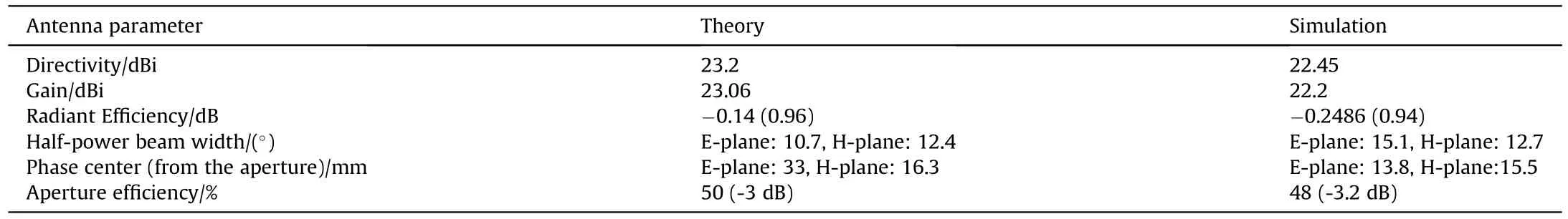
Table 4 Comparison between calculated values for the antenna performance and simulation results [37].
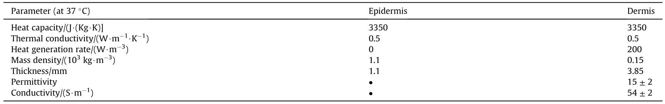
Table 5 Comparison between calculated values for the antenna performance and simulation results [37].
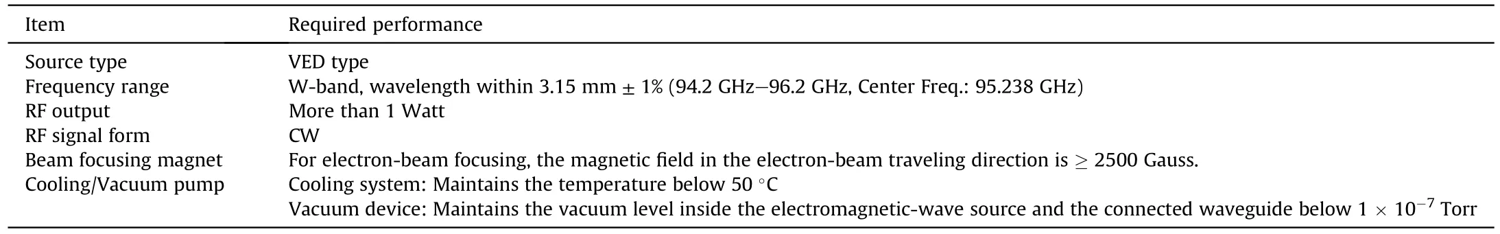
Table 6 Experimental items of CCBWO.

Table 7 Experimental items of HV-PS
Conventionally,permanent magnet or solenoid is used for beam focusing,but it is very bulky and not compatible when someone is thinking about compact THz device.The compact permanent magnetic system was designed by using quite simple approach.It does not need any brazing and pole-pieces (for holding magnet)arrangement.Different diameter and axial length Nd-38 permanent magnet rings and optimized for uniform axial magnetic field are used to the focusing system.The minimum axial brillouin field calculated using this formula,which was~1000 Gauss.Numerically measured axial magnetic field strength well match with simulated profile.
In this study,a single stage depressed collector was used.The inner and outer spaces are isolated,and this is to separate the depressed collector from the external ground because the voltage of the depressed collector is generally the same as that of the negative electrode.The separated inner and outer spaces prevent the heat generated in the inner collector space from affecting the outside.Since the collector voltage is much lower than the voltage of the anode,a retrograde force is applied in the collector space,and the speed gradually decreases,and the electrons reaching the collector have the effect of being recovered back to the power supply.
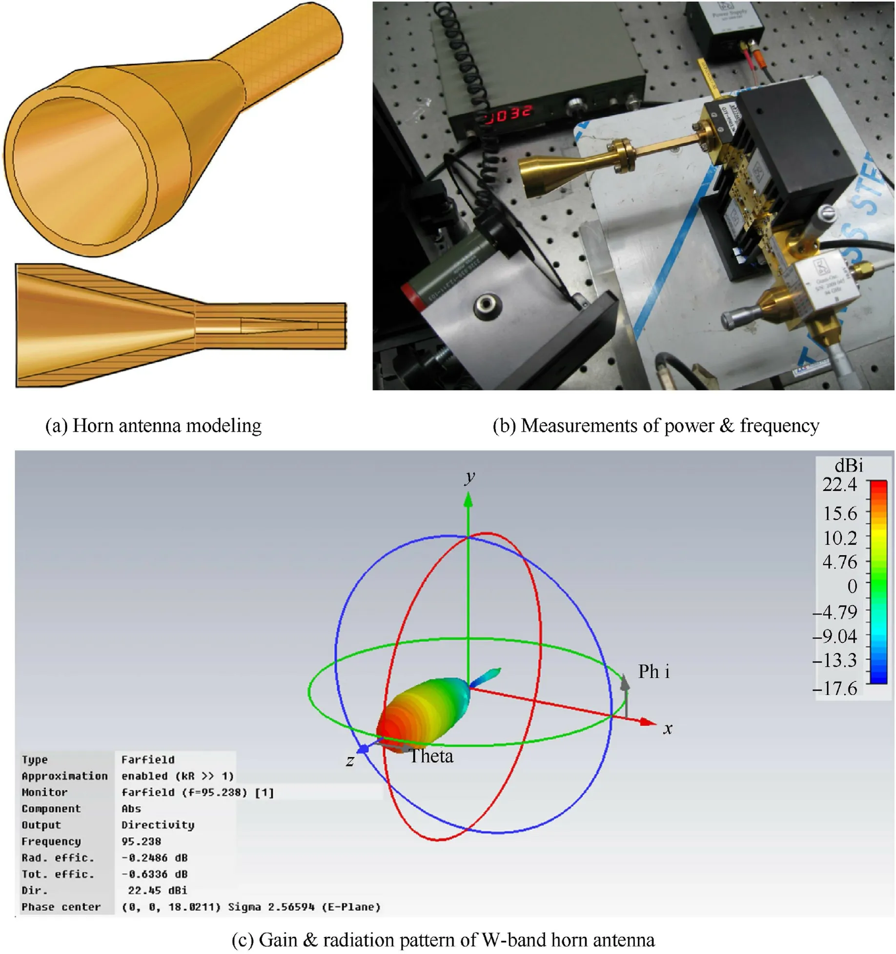
Fig.9.Horn antenna (W-band): two-dimensional and 3D modeling,measurement,and radiation pattern.
The Depressed Collector principle can be explained as follows.The following Fig.12 compares the circuit of the general collector and the depressed collector.In the VED Tube,the electron beam is converted into thermal energy due to body loss in the circuit before the collector and other paths,RF output according to the interaction with the RF circuit,and finally,collision with the collector.The efficiency of this tube is given as (RF output/loss in circuit output) × 100 (%).In the case of Fig.12(a),the general collector is shown.In the case of the general collector,the loss output in the circuit corresponds to all of the first incident energy of the electron beam,so the efficiency is given as (RF output/electron beam input output) × 100 (%).On the other hand,Fig.12(b) shows the Depressed Collector.In this case,the incident electron beam is repelled by the collector and gradually loses its kinetic energy,sothat the generation of heat due to the collision is significantly reduced.From an electrical point of view,the current collected by the collector is consumed as heat by a relatively low voltage,and a large amount is recovered.That is,the efficiency becomes [RF output/(electron beam incident output-collector recovery output)]×100(%),and the higher the collector output,the higher the efficiency.
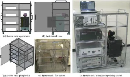
Fig.10.System rack.
Regarding the stabilization of the cathode power supply,in the case of a general collector,the number of cases where the collector collision current,which accounts for most of the electron beam,flows out to the ground and directly affects the cathode power supply,is high.However,in the case of a depressed collector,it is affected by the collector power supply,which does not require relatively stability,thus increasing the stability of the tube.When designing the detailed design based on this,the design of the Depressed Collector was designed with the minimization of heat generation and suppression of secondary electrons entering the circuit in mind.Collector power supply design was performed considering the following.The power relationship between cathode,anode,and collector used in this project is designed as shown in the figure below.The power supply of the depressed collector is divided into two cases of 6 kV and 9 kV,and a suitable collector is selected through other M&S.The basic structure is the same as Fig.12(b),and unlike the general Depressed Collector,the body and the collector are independently designed with a separate power supply.The design schematic is shown in Fig.13.First,considering that 1%of the electron beam incident output is RF output,the-6kV collector has an efficiency of 2% and a recovery efficiency of 50%.And the RF efficiency of -9kV collector is 3% and the recovery efficiency is 75%.
The ion pump gauge can be checked in the ion pump system including a gauge,a controller with a power supply at the end of the electron gun connection part in Fig.14.CCBWO,which has been manufactured and assembled,has been subjected to a baking-out process for a long time as shown in Fig.14(a) so that it can maintain a high vacuum state even during normal times.This is by installing an electron gun and tube in the Baking-out system,in addition to pulling out the internal vacuum through the rotary pump,fine dust and impurities remaining in the tube come off with high heat,and it is pumped with air.It is an operation to ensure a stable situation in which impurities have been removed.In this initial baking,if the vacuum degree in the tube is maintained below torr after pumping for 48 h,baking at 400C.for 72 h is performed.Cathode Activation is the process of supplying sufficient power to the cathode before using the first electron gun,applying a lower beam voltage to a higher beam voltage gradually to release the coatings on the cathode surface and breaking the initial seal of the cathode so that the electrons are properly emitted.It's work.Through this process,it is possible to check whether the electron gun is properly manufactured as designed.
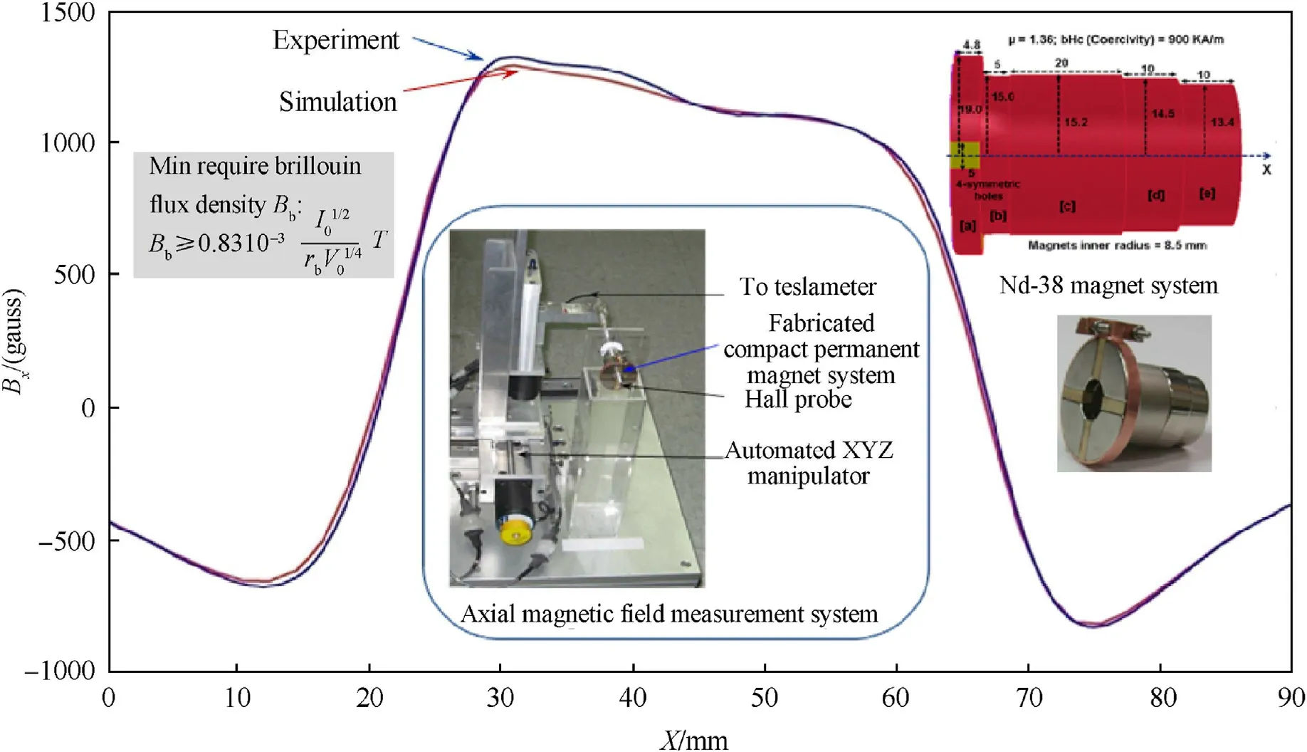
Fig.11.Measurement of the magnetic field for the permanent magnet.
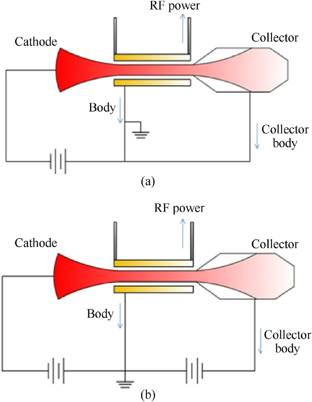
Fig.12.Description for collectors;(a) a general collector,(b) a depressed collector.
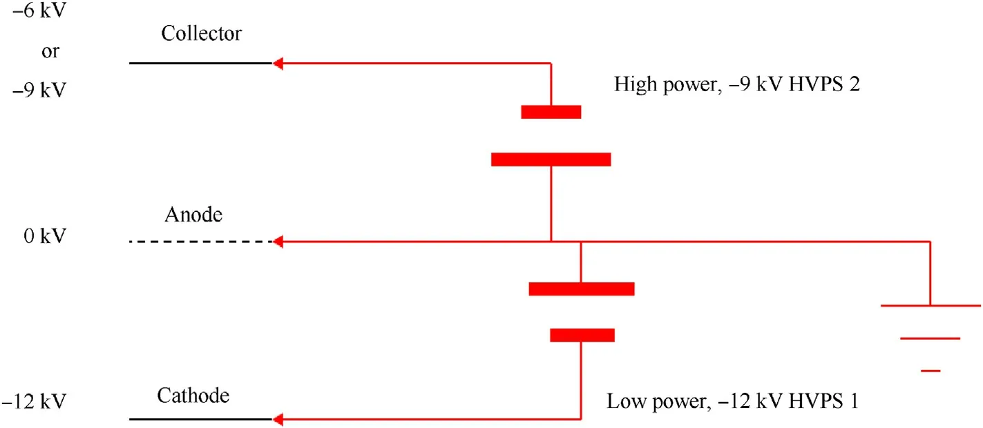
Fig.13.Design on the depressed collector power supply.
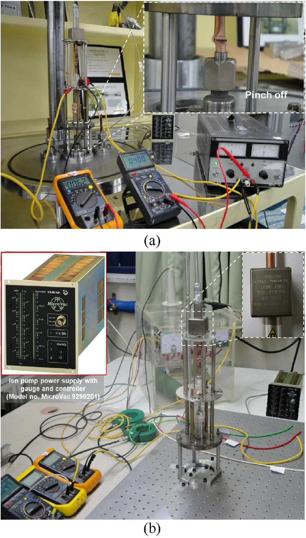
Fig.14.CCBWO test;(a) Pinch off after baking-out,(b) Hot test equipped with ion pump system.
Regarding the degree of vacuum,an ultra-high vacuum of 1 × 10torr or less is required.The electron gun may be contaminated due to the generation of a lot of gas during the first cathode activation,so it was designed to interlock the ion pump.As shown in Fig.14(b),it was designed so that the ion pump could be connected at the back of the electron gun(in the direction opposite to the beam propagation).It is manufactured by Varian,and the model name is 2 l/s Pump.It is possible to bake up to 400C.It is an ultra-light size and weighs 0.9 kg.It can maintain vacuum up to ultra-high vacuum of 1×10torr or less.It consists of a 2 l/s ion pump,a magnet,and a controller.The ion pump power is supplied through the controller,and the degree of vacuum can be checked.The magnet corrects the movement of ions inside the pump.And as shown in Fig.14(b),if the ion pump system is operated during the hot test,it is possible to check the vacuum level.At this time,the vacuum state is ultra-high vacuum and is maintained at a level of 10to 10torr.
Fig.15 shows the electron beam current-voltage (I-V) test curves for the CCBWO circuit.For the beam outputs of 5.31 W and 6.19 W,the current with respect to the voltage of the electron beam was measured and plotted.The measured beam current and perveance values were 0.0283 μP (slightly lower than the simulation)when the beam acceleration voltage was increased to 1 kV with the heater power of 5.31 W or 6.185 W supplied as the default.A lower beam perveance implies that the beam density is lower than the design value,which can cause the following two problems.First,the interaction between the beam and the circuit in the interaction circuit is weakened,reducing the output RF power.Second,because the repulsive force between the internal electrons due to the low current density is weakened,there is a high probability that the electrons cross each other before being incident to the anode.
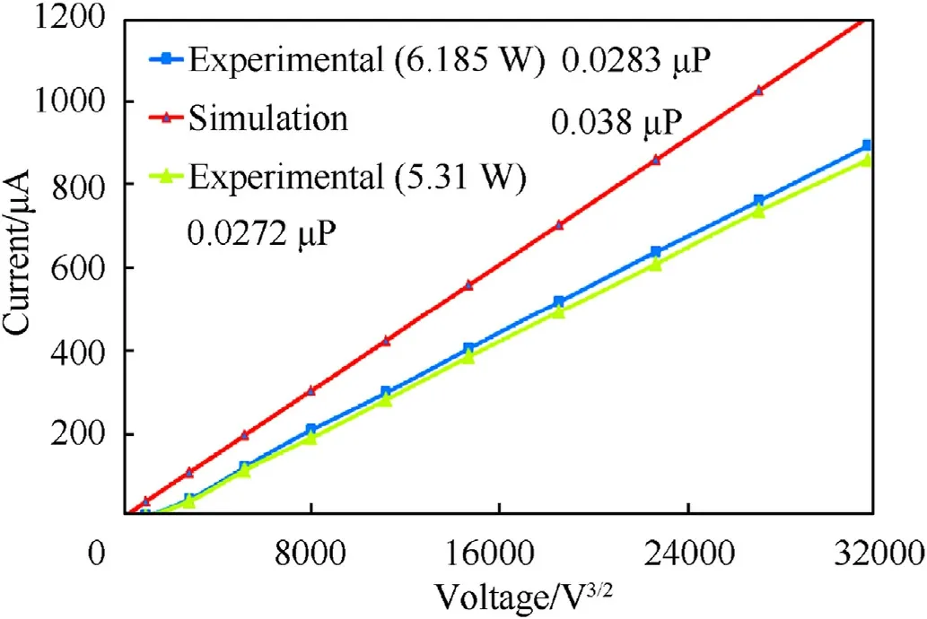
Fig.15.Electron beam I-V test result (beam perveance).
To resolve these issues,the following follow-up measures were taken.To maintain the beam perveance,the beam-focusing electrodes (BFEs) were operated independently of the cathode by raising 3 V relative to the cathode.Consequently,as shown in Fig.16,the beam-current value,which was lower than that of the simulation,became identical to that of the simulation [37,38].
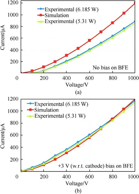
Fig.16.I-V test result;(a) No bias on BFE,(b) +3 V on BFE.
The results of the beam current test generated versus the applied beam voltage in the electron gun performance test with the configuration shown in Fig.14(b)are shown in Fig.17.In addition to experimental data,it was compared with E-gun 2D code,TRAK 2D code,and OPERA 3D code,which are electron gun simulations.Fig.17 shows that the tendencies are generally consistent,including the range of beam voltage and current.Beam voltages of up to 12 kV and beam currents of up to 50 mA are close to the initial design goals.Finally,beam emission experimental data agrees fairly with numerical simulation results.This tested high current electron beam source was successful attempted to fill the need of beam requirement for W-band (0.075-0.110 THz) vacuum electron devices.This cylindrical e-beam source has capability to satisfy beam current density requirement for THz-VEDs like 95 GHz planar coupled-cavity BWO.
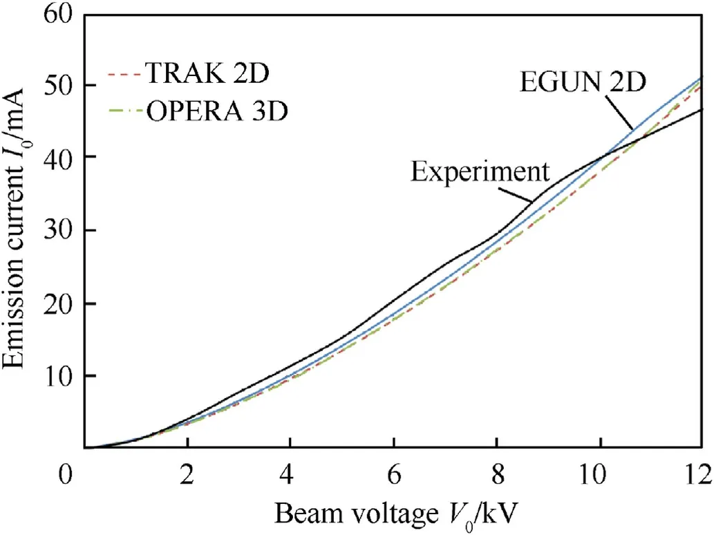
Fig.17.Emission characteristics of E-Gun (comparison of experiment with simulations).
Fig.18(a)shows the measured RF output power type and ranges according to the value of beam current in the circuit of CCBWO.Fig.18(b) shows the values measured by FFT (Fast Fourier Transform) using the double heterodyne method for the operating frequency corresponding to the RF power oscillating through CCBWO.For these measurements,refer to Fig.8.In Fig.18(a),when the beam current is 30 mA,after 50 ns oscillation occurs,it is stabilized to 1 W at the operating frequency of 95 GHz and radiated through the antenna.In the case of 40 mA and 50 mA,it proceeds to the level of 3 W and 5 W,respectively,and after 600 ns and 800 ns,respectively,the power decreases and then stabilizes and oscillates with an RF power of a little over 1 W.
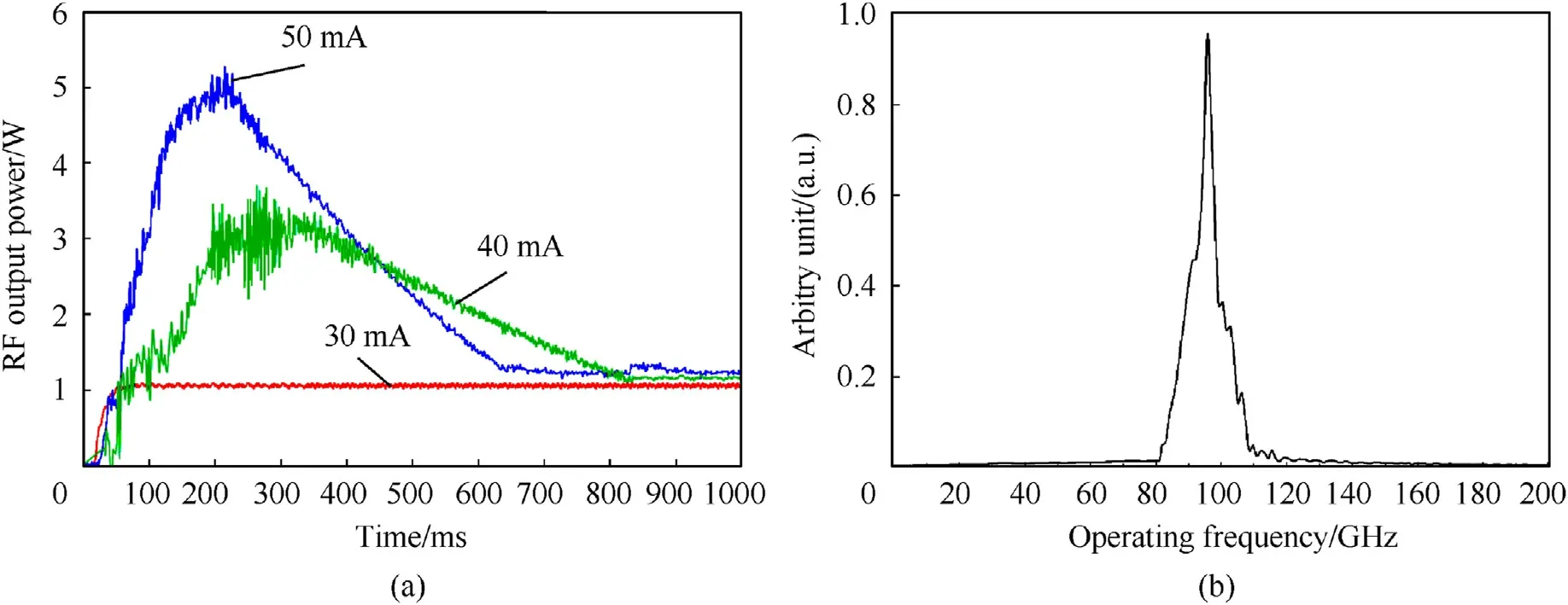
Fig.18.Experimental results for CCBWO;(a) time vs.RF output power,(b) operating frequency.
Fig.19 shows the RF output power according to the beam current.Here,the starting oscillation bema current is around 25 mA,and in the case of 30 mA,RF power was measured as 1 W.As a function of the CW,the electromagnetic wave continuously stabilized in the frequency mode of 95 GHz can be radiated through the antenna.However,in the beam current of 40 mA and 50 mA,which exceeds the beam current of 30 mA,the maximum value of RF power is initially reached,and after a certain period of time,it becomes 1 W class,after which stabilization is possible.However,the decrease in RF power at the point of reaching the maximum value after starting oscillation and stabilization increases the beam instability in the CCBWO circuit over time,and the growth rate(in the CCBWO circuit in the CCBWO circuit) In the wavenumber and frequency relationship for the generated electric field solution,the real domain represents the dispersion relation,and the imaginary domain represents the growth rate,which is closely related to the performance ratio of beam instability) is assumed to be the main factor.In addition,since space charge compensation is not performed properly due to the space charge limit effect according to the beam perveance in the CCBWO circuit,a critical current occurs in the CCBWO circuit,breakdown occurs,power loss occurs,and then the beam current is stabilized after a certain period of time.It can be explained as a mechanism.However,this can also result in circuit damage and shortening its lifespan.
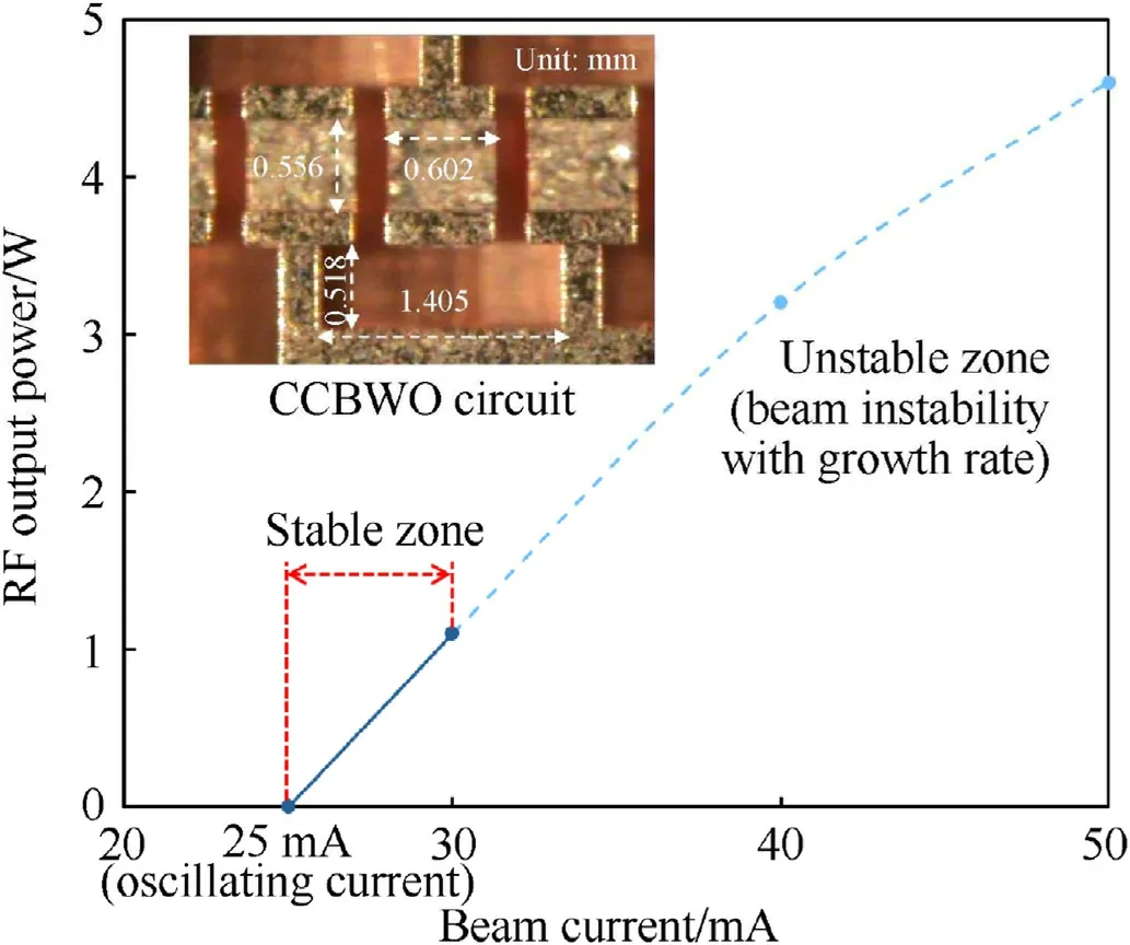
Fig.19.Experimental results for CCBWO;beam current vs.RF output power.
4.2.Test cell
As shown in Fig.20,an IR camera was installed in the test cell chamber and linked to the control personal computer (PC) via Universal Serial Bus (USB).The controller was used to check whether the infrared image was transmitted and whether the temperature change was detected.
Optical properties exist in the skin of the human body in the sub-terahertz frequency region applied to this study.In this region,the absorption rate for water is high and the absorption for blood is small,so it appears differently depending on the skin wavelength,the type of tissue,and the characteristic state of the tissue.However,it is affected by the optical properties in the living tissue.Specifically,it comprises a human-like phantom layer comprising pure water,methanol,and sodium chloride,and a signal measuring sensor layer provided above the human-like phantom layer and measuring charging efficiency and temperature change for performance evaluation characterized by being And as a method of manufacturing a phantom similar to human skin;(1)dissolving by mixing and heating methanol,and sodium chloride in a liquid state of pure water;(2) cooling the dissolved liquid while stirring;(3)preparing a gel-like state when the dissolved liquid reaches a predetermined temperature;(4) It is characterized in that it includes the step of constructing a signal measuring sensor that measures permittivity,conductivity,temperature change,etc.for performance evaluation through the human skin-like phantom[45-47].
Fig.20.Connection of infrared camera,test cell,and controller laptop.
To simulate the targeted human skin,a solution of pure water(100 mL),methanol (100 mL),and sodium chloride (1.8 g) was placed in a plastic container.As shown in Fig.21,the relative permittivity and conductivity of the mixed solution were measured using a W-band vector network analyzer (VNA) and a laptop computer (Fig.21(a)).After a chalet was prepared,as shown in Fig.21(b),the measured mixed solution was poured into the chalet to form a target whose temperature change could be detected,and it was sealed with a thin plastic film.The initial temperature of the solution in the chalet was measured as room temperature (21C).As shown in Fig.21(c),a chalet was prepared and placed at the center of the test cell,and whether the installed infrared camera could properly observe the chalet was checked.Thus,the chalet was located at the center of the infrared imaging.An open end probe method was used in the dielectric constant measurement method Refs.[34,48,49].
As shown in Fig.22(a),the VNA and the 85070 E dielectric probe kit were connected,and the relative permittivity and conductivity of the mixed solution were measured using the relative permittivity and conductivity measurement program.The measured relative permittivity and conductivity of the mixed solution are shown in Fig.22.The distance between the IR thermal imaging camera and the sample is approximately 80 mm in Fig.22(c).
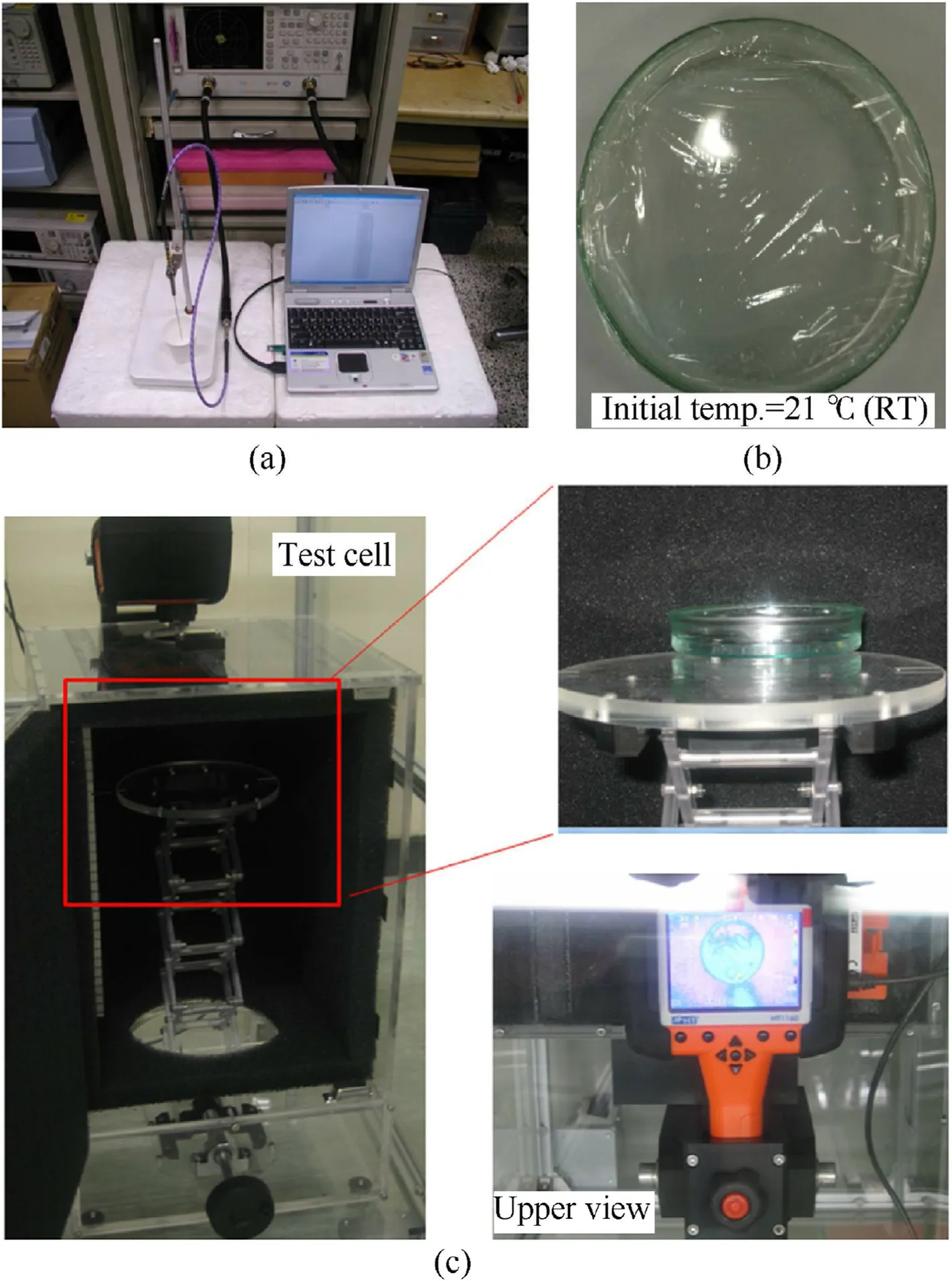
Fig.21.Configuration of the dielectric constant and conductivity experiment on a human hair sample (target) using an infrared imager;(a) target test;(b) chalet;(c) test cell composition.
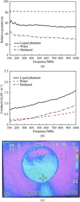
Fig.22.Results of the target test: (a) permittivity of the human simulated sample.(b) conductivity of the human simulated sample.(c) IR camera image for the increased temperature.
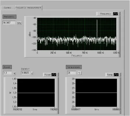
Fig.23.Operating frequency,measured output power,and temperature of the collector from the CCBWO.
Fig.23 presents the frequency range,RF output,signal duration,and temperature measurement results from the control PC system shown in Fig.10(e).Referring to Fig.23,the operating frequency of the controller PC(laptop)was measured to be 94.3467 GHz.The RF output power was approximately 1.3 W,and the temperature of the solution in the chalet (the target) was measured to be approximately 26C from Fig.22(c).Considering that the initial temperature before the experiment was 21C,it was confirmed that the temperature of 5C was increased for approximately 10 s.The overall results for the test cell are presented in Table 8.
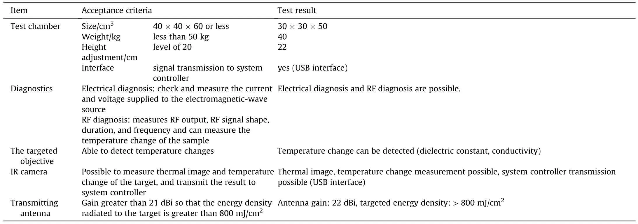
Table 8 Test cell test items and experimental results.
5.Conclusions
The CCBWO,which has the characteristics of CWs of a specific wavelength,generates a high-power mm/terahertz electromagnetic wave of several watts.It was used to construct a cell-type continuous electromagnetic wave radiation demonstration device that can observe the effect of the radiation on living things.This system converts the electron energy of the electron beam into RF energy by the electromagnetic-wave source and radiates it to the target through an antenna,causing pain due to a temperature rise through RF energy absorption of the skin and ultimately reducingcombat power.It is expected to directly or indirectly affect the skin of living things by generating high-frequency,high-power RF signals.A cell-type continuous electromagnetic wave radiation device consisting of an HV-PS,electromagnetic-wave source,test cell,and system controller generates an RF signal of ≥1 W in CW at a central frequency of approximately 95 GHz and uses a chemical solution with a dielectric constant similar to that of the skin of a living organism.A temperature increase of approximately 5C occurred in 9.9 s.There is a need for multifaceted research on the skin and research on an efficient source structure.
The authors declare that they have no known competing financial interests or personal relationships that could have appeared to influence the work reported in this paper.
This work was supported by the National Research Foundation of Korea(NRF) grant funded by the Korea government(MSIT)(No.NRF-2021M2E8A1038938,No.NRF-2021R1F1A1048374,and No.NRF -2016R1A3B1908336).This study was also supported by a grant of the Korea Institute of Radiological and Medical Sciences(KIRAMS),funded by the Ministry of Science and ICT (MSIT),Republic of Korea(No.50051-2021,No.50623-2021).We would like to thank Editage(www.editage.co.kr)for English language editing.

- Defence Technology的其它文章
- Establishment,simulation and verification of firepower safety control model
- Burning characteristics of high density foamed GAP/CL-20 propellants
- Sandwich structure for enhancing the interface reaction of hexanitrohexaazaisowurtzitane and nanoporous carbon scaffolds film to improve the thermal decomposition performance
- Ablation characteristics of insulator under high-temperature gas dualpulse erosion
- Influence of shaped charge structure parameters on the formation of linear explosively formed projectiles
- Novel aluminum-based fuel: Facile preparation to improve thermal reactions