
Experimental study on dynamic stall control based on AC-DBD actuation
2021-11-30 08:28:50HesenYANG楊鶴森HuaLIANG梁華GuangyinZHAO趙光銀BoWANG王博ShengwuZHANG張圣武andWeiliangKONG孔維良
Plasma Science and Technology 2021年11期
關(guān)鍵詞:王博
Hesen YANG(楊鶴森),Hua LIANG(梁華),?,Guangyin ZHAO(趙光銀),Bo WANG(王博),Shengwu ZHANG(張圣武) and Weiliang KONG(孔維良)
1 Science and Technology on Plasma Dynamics Laboratory, Air Force Engineering University, Xi’an 710038, People’s Republic of China
2 State Key Laboratory of Aerodynamics, China Aerodynamics Research and Development Center,Mianyang 621000, People’s Republic of China
3 National Key Laboratory of Rotorcraft Aeromechanics, Nanjing University of Aeronautics and Astronautics, Nanjing 210016, People’s Republic of China
4 Institute of Noise & Vibration, Naval University of Engineering, Wuhan 430030, People’s Republic of China
5Academician Workstation Foundation of the Green Aerotechnics Research Institute of Chonging Jiaotong University, Chongqing 401120, People’s Republic of China
Abstract To explore AC-DBD’s ability in controlling dynamic stall, a practical SC-1095 airfoil of a helicopter was selected,and systematic wind tunnel experiments were carried out through direct aerodynamic measurements.The effectiveness of dynamic stall control under steady and unsteady actuation is verified.The influence of parameters such as constant actuation voltage,pulsed actuation voltage, pulsed actuation frequency and duty ratio on dynamic stall control effect is studied under the flow condition of k = 0.15 above the airfoil, and the corresponding control mechanism is discussed.Steady actuation can effectively reduce the hysteresis loop area of dynamic lift,and control the peak drag and moment coefficient.For unsteady actuation,there is an optimal duty ratio DC = 50%, which has the best effect in improving the lift and drag characteristics,and there is a threshold of pulsed actuation voltage in dynamic stall control.The optimal dimensionless frequency will not be found; different F+ have different control advantages in different aerodynamic coefficients of different pitching stages.Unsteady actuation has obvious control advantages in improving the lift-drag characteristics and hysteresis, while steady actuation can better control the large nose-down moment.
Keywords: dynamic stall, plasma flow control, AC-DBD, parameter, control law
1.Introduction
Dynamic stall refers to an unsteady phenomenon caused by violent flow separation with the angle of attack cyclically changed [1, 2], which always exists in rotorcraft retreating blades, surging compressors and wind turbines [3].
The dynamic stall phenomenon is dominated by the leading edge detachment vortex, and the rapid backward movement of the detachment vortex causes the backward movement of the pressure center, bringing about a violent nose-down moment and a significant increase in the torsion load of the airfoil [4].Due to the dynamic effect, the stall angle of the oscillating airfoil is generally larger than that of the static stall angle under the same incoming conditions,which can increase the maximum lift force.However, once the stall angle of attack is exceeded, the generation, movement and shedding of the dynamic stall vortex (DSV) will form a very complex flow phenomenon, resulting in great drag increase, causing steep stall and flutter load problems with a sharp drop in lift [5].Especially for the helicopters,dynamic stall will greatly limit the flight aerodynamic performance, leading to instability of pilot operation, and the most direct adverse effect is to limit the maximum forward speed of the rotors [6].Hence, it is essential to improve the aerodynamic performance of helicopter rotors to alleviate the high drag and violent nose-down moment, and make full use of the dynamic vortex lift [7].
During the past 10 years, the dielectric barrier discharge(DBD)plasma actuation has been extensively researched due to its advantages of simple construction, no moving components, broad frequency band and fast response.Recently,nanosecond dielectric barrier discharge (NS-DBD) has attracted attention in the field of dynamic stall control by virtue of its stronger disturbance ability to the flow field[8,9],while alternating current dielectric barrier discharge (ACDBD) is the most widely used actuation method.Compared with NS-DBD, AC-DBD has smaller electromagnetic interference.In addition, AC-DBD has been shown to reduce the leading edge flow separation under a high angle of attack,and provide flight lift in static boundary layer control [10, 11].Hence, scholars have gradually applied it to the flow control of oscillating airfoils,and have found that AC-DBD actuation has the potential to realize dynamic and effective control of airfoils [12].Mitsuo K [13] and Lombardi A J [14] verified that AC-DBD actuation could ease the lift hysteresis in dynamic stall.Sekimoto S [15] concluded that the separated flow could be reattached on the downstroke of an oscillating NACA 0015 airfoil.
AC-DBD actuation inevitably involves steady actuation and unsteady actuation.For static separation control,the flow control effect of unsteady AC-DBD actuation is better than that of steady (continuous) AC-DBD actuation [16].However, there is a lack of systematic quantitative comparative study for these two discharge modes under dynamic stall control condition.Furthermore, AC-DBD’s ability to control the dynamic stall of the airfoil under a more severe flow environment over the airfoil has not been proven.Wind tunnel experiments in more severe flow fields are urgently needed.Previous research has paid more attention to the flow parameters, but lacked the detailed study of the plasma actuation parameters, such as actuation voltage, actuation frequency, duty ratio, and the corresponding control laws,which also need to be further summarized to guide the optimization of flow control methods.From the research objective of dynamic stall control experiments, basic airfoils have previously been the focus, whereas typical helicopter retreating blades have rarely been given attention [8].
Therefore, in the designed dynamic stall control experiments,the effectiveness of dynamic stall control under steady actuation and unsteady actuation at k = 0.15 and U∞=30 m s?1is verified, and a quantitative comparative study is completed in a wind tunnel.The influence of different constant actuation voltages for steady actuation, different pulsed actuation voltages, pulsed actuation frequencies and duty ratios for unsteady actuation on the dynamic stall control effect is studied.Based on the analysis of the control results,the corresponding control laws are summarized for large k and high incoming freestreams.
2.Experimental system design and introduction
Aerodynamic experiments were carried out in the helicopter wind tunnel of NUAA.The tunnel has an open experimental section measuring 3.4 m (height) × 2.4 m (width) × 5 m(length) in cross-section, and has a flow velocity range of 5–60 m s?1.The dynamic pressure uniformity of each section is good.The axial turbulence of the flow is 1.44%–2.31%,and the average deviation angle of the airflow is Δα = 0°and Δβ = 0.08°.For the UH-60 helicopter’s application background, an SC-1095 airfoil was selected [17].The airfoil’s chord length is 0.3 m and the span length is 0.75 m.The layout of the test section is shown in figure 1.
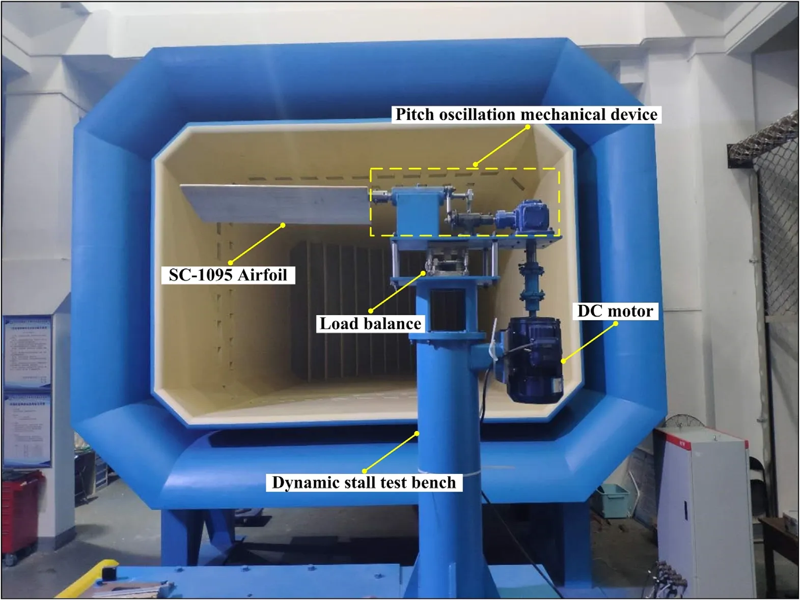
Figure 1.Layout of wind tunnel experimental section.
The DBD plasma actuator consists of insulating medium and an electrode[18].Three layers of Kapton tape are used as an insulating medium.The dielectric constant is 3.5, the thickness is 0.2 mm, and the withstand peak voltage value is not less than 15 kV.The electrode is made of copper.The width of the high-voltage exposed electrode over the lower surface is 5 mm, the width of the low-voltage covered electrode over the upper surface is 10 mm, and the middle gap is zero.The actuator is arranged on the leading edge of the airfoil, as shown in figure 2.The covered electrode is arranged over the upper airfoil surface of the leading edge, while the exposed electrode is arranged over the lower airfoil surface.The discharge area is located over the upper surface and the length of the actuator on both sides is 75 cm.
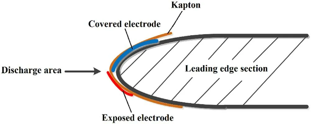
Figure 2.Actuator layout at the leading edge of the airfoil.
A CTP-2000K millisecond pulsed plasma power supply[19] was used in the experiment to actuate the plasma actuator.The input voltage was 0–220 V and the output waveform was sinusoidal.The output voltage is 0–30 kV,and is continuously adjustable.The discharge frequency (carrier frequency) is 6–40 kHz, continuously adjustable.The pulsed actuation frequency is 10–1000 Hz, continuously adjustable.The duty ratio is 1%–100%, adjustable.
The discharge parameter testing system consists of a highvoltage probe,current probe and digital oscilloscope to measure the discharge voltage and current of the actuator [9].Figure 3 shows the voltage(V)-current(I) signals collected when the actuation peak-to-peak voltage Vp-p= 9 kV,the pulsed actuation frequency fp= 200 Hz, and the duty ratio DC = 50%.
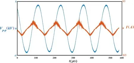
Figure 3.Voltage-current signals of AC-DBD actuation.
The airfoil oscillation drive device is controlled by frequency converter and DC motor, and the regular pitching oscillation of the airfoil is realized by the combination of an eccentric wheel, a connecting rod, a reducer and other mechanical devices connected to the SC-1095 airfoil.The angle sensor is mounted on the rotating shaft of the airfoil to determine whether the specified angle position is precisely satisfied.After the DC motor starts, the airfoil is always pitching with a quarter point of its chord line.
The real-time variation of the airfoil’s α constitutes the airfoil motion profileα(t) .α(t) is determined by the mean angle of attack α0, motion amplitude αm, and angular pitch rate ω.The calculation method isα(t) =α0+αm×sin(ωt)[8, 20]; among themω=π2f, f is the airfoil’s oscillation frequency and t is time.α0, αmand f can all be precisely adjusted by the pitching motion system,as shown in figure 4.In addition, α0and αmwill be checked between different trains of wind tunnel experiments to ensure the consistency of the motion curve.
A six-component cassette load balance, as shown in figure 1,is used to obtain and store the aerodynamic force and moment.The load can be measured directly.DHDAS(Dynamic Signal Acquisition and Analysis System)is used to display and save the aerodynamic data in real time [8].The acquisition frequency was set to 5000 Hz during the experiment.It is proved that DHDAS can deal with the dynamic periodic signal well [21].
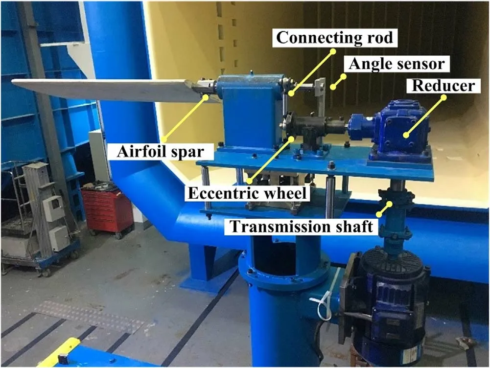
Figure 4.Experimental airfoil pitching motion system.
3.Experimental results and data analysis
Static characteristics were measured first, and the static stall control capability of plasma actuation was verified before dynamic stall control experiments.
Static experiments were conducted under the condition of Re = 650,000, U∞= 30 m s?1and temp = 25 °C.Figure 5 presents the static results.In this figure, Clrepresents the lift coefficient, Cdis the drag coefficient, Plasma off represents the baseline flow, and Plasma on represents the actuation state.Two actuation frequencies are selected, and actuation voltages for every value of α were set at Vp-p= 8 kV.It can be concluded that the static stall α is 19°.Under the actuation state, whether it is F+= 1 or F+= 2, the stall α is delayed to 21°, the peak Clis significantly improved and the drag is effectively controlled.
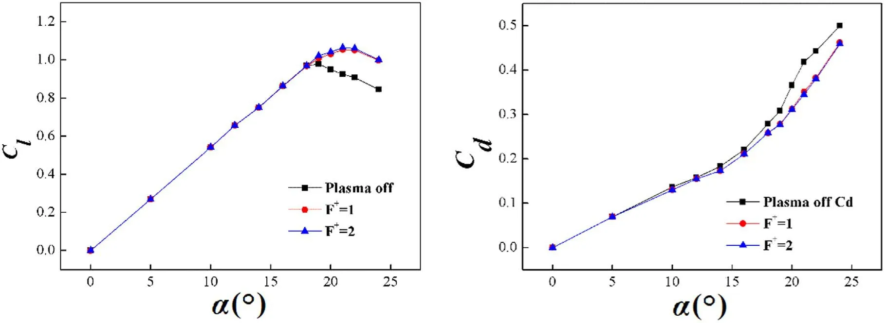
Figure 5.Static flow control results.
The control effect under different F+has little difference.In comparison, the increase effect of F+= 2 near the stall angle of attack is more obvious, but it is undeniable that the increase of lift and the effect of delaying the stall with F+= 1 and F+= 2 are both significant.
Based on the static experimental results at Re = 650,000 and the AC-DBD actuation’s ability to delay stall, a motion proflie ofα(t) = 16° + 8° sin (ωt)is determined.Hence, the range of angles of attack(α = 8°–24°)is set.On one hand,it can make the aerodynamic change process of dynamic stall to be fully demonstrated;on the other hand,it can ensure that the latent energy of AC-DBD to control dynamic stall is fully explored.
When the freestream velocity and Reynolds number are determined,the dynamic stall of the airfoil is not only related to α0and αm, but also a very important parameter, namely the reduced frequency.This concept comes from the dimensionless approach to the incoming flow speed and the oscillation frequency of the airfoil in the dynamics of helicopter rotors[22].
The reduced frequency k is used to describe the unsteadiness of flows over airfoils and wings [23].It is defined as the ratio of convective time scales(c/2U∞)and the time scale of forced oscillation (1/2πf) [8, 24].For c (m), f (Hz),ω = 2πf (rad s?1) and U∞(m s?1), the reduced frequency is defined as: k = πfc/U∞.Obviously, for one airfoil, once f is determined, the reduced frequency is uniquely determined with the freestream velocity unchanged.
The range of the helicopter rotor’s airfoil operation reduced frequency is generally from 0.03 to 0.15 [25, 26].Most of the previous studies on dynamic stall control have focused on the range less than k = 0.05, but there are few studies on large reduction frequency, especially k = 0.1 and above.In consideration of practical application, subsequent dynamic stall control experiments were conducted under the condition of k = 0.15 to probe the boundary of control ability of AC-DBD, corresponding to f = 4.77 Hz.
Therefore, the control effects of AC-DBD actuation were investigated for Re = 650,000, k = 0.15, various constant actuation voltages (constant Vp-p= 8–10 kV), various pulsed actuation voltages (Vp-p= 8–11 kV), various dimensionless actuation frequencies(F+= 0–10)and duty ratios(DC = 10%–70%)withα(t) = 16° + 8° sin (ωt).The pneumatic data were directly measured for subsequent summary of control laws.
3.1.The effect of steady actuation
Flow of baseline at k = 0.15 was investigated before setting different actuation states.The black curves in figure 6 show the base flow under motion profile of α(t) = 16° + 8°sin(ωt)at k = 0.15.The lift coefficient increases almost linearly to the peak from 8° to the maximum α (α = 24°).As soon as the airfoil enters the downstroke, Clbegins to drop until α = 11°.Then the lift coefficient recovers slightly and returns to the lift level of the upstroke at α = 10°, and remains higher throughout α = 10° down to α = 8°.
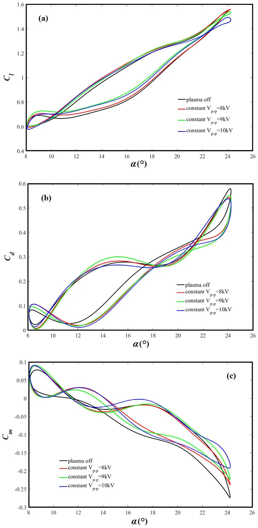
Figure 6.Experimental results of steady actuation(k = 0.15).(a)Cl,(b) Cd, (c) Cm.
Dynamic stall usually occurs when the maximum α is minimally higher than the static α [24].At this moment, the DSV is shed due to speed reduction and pitching direction change, creating a violent boundary layer separation, and leading to fully separated flow.
Meanwhile for k = 0.15,the response of DSV above the airfoil will be affected to a certain extent due to the high pitch speed of the airfoil, which will lead to the delay of dynamic stall phenomenon.Based on the baseline, dynamic stall does not occur until the airfoil moves to the maximum α,which is different from the previous study under a low reduced frequency condition where the stall occurs at a larger angle of attack on the upstroke.
Figure 6 shows the results for various actuation voltages under steady actuation (constant discharge) at k = 0.15.The carrier frequency of the power supply in the experiment of this section is set to 8 kHz.For Vp-p= 8 kV, the lift coefficient after actuation is not improved until the airfoil pitches down to α = 20°, and the improvement is very slight, as shown by a slight increase.When Vp-p= 9 kV or 10 kV, the trend of the lift curve around the maximum α changes.It can be seen that the lift coefficient does not decrease immediately at the beginning of the downstroke,but that it appears after a small increase.Unfortunately, even so, the peak lift coefficient is not increased controlled by Vp-p= 9 kV and Vp-p= 10 kV when compared with the baseline flow.As the airfoil continues to pitch down, the control advantage of larger constant discharge actuation becomes apparent.The lift of most of the angle of attack on the downstroke can be greatly increased at Vp-p= 9 kV and Vp-p= 10 kV.In comparison,the lifting effect of Vp-p= 10 kV is better,but the lift loss near the maximum α is also relatively larger.The loss of peak lift does not affect the alleviation of aerodynamic hysteresis caused by dynamic stall,and a reduction in the area of the hysteresis loop is obvious.When Vp-p= 10 kV, the area is maximally reduced by 10.6%; Vp-p= 9 kV,Vp-p= 8 kV respectively correspond to 8.8% and 3.2%.
The loss of the peak value of lift coefficient and stall delay can be explained; when the constant discharge voltage increases to a certain extent, the accelerating effect of the leading edge shear layer induced by steady actuation is enough to destroy the inherent structure of DSV and it also can delay the shedding of DSV over the airfoil.Hence, the effect of DSV on increasing lift force is weakened, and the angle which corresponds that the lift coefficient begins to drop is also delayed.
In terms of drag coefficient and moment coefficient, the drag coefficients on the upstroke and near the maximum angle are reduced under actuation,and the large nose-down moment is also controlled.With the increase of constant voltage,the control effect of drag and moment is better.When Vp-p= 10 kV, the peak drag coefficient can be reduced by 7.3%and the peak value of the large nose-down moment can be reduced by 29.6% at most.This also proves that steady AC-DBD actuation can control and improve DSV to a certain extent.
3.2.The effect of unsteady actuation
References [11, 27] believe that pulsed AC-DBD actuation(unsteady actuation) has a better control effect than constant AC-DBD actuation (steady actuation) in flow separation control.Because the pulsed AC-DBD actuation is modulated by millisecond pulse, it is called millisecond pulsed DBD actuation.Therefore,it is necessary to try and verify the effect of unsteady AC-DBD actuation in dynamic stall control.
Different parameters involved in the modulation process are considered in this section, and the influence of different duty ratios, different pulsed actuation voltages and different pulsed actuation frequencies is studied successively.The other experimental parameters are the same as the steady actuation study.
3.2.1.Flow control effect of different duty ratios.Duty ratio is actually the proportion of pulsed actuation signal in a discharge cycle, which is a unique concept in unsteady actuation research [28].When the duty ratio of the power supply is set to 100%, the generated actuation is the steady actuation.
Four duty ratios were selected to explore the effect of duty ratio control, respectively 10%, 30%, 50% and 70%.During the experiments, the pulsed actuation voltage and pulsed actuation frequency remained unchanged at Vp-p=8 kV and F+= 1.Results are shown in figure 7.
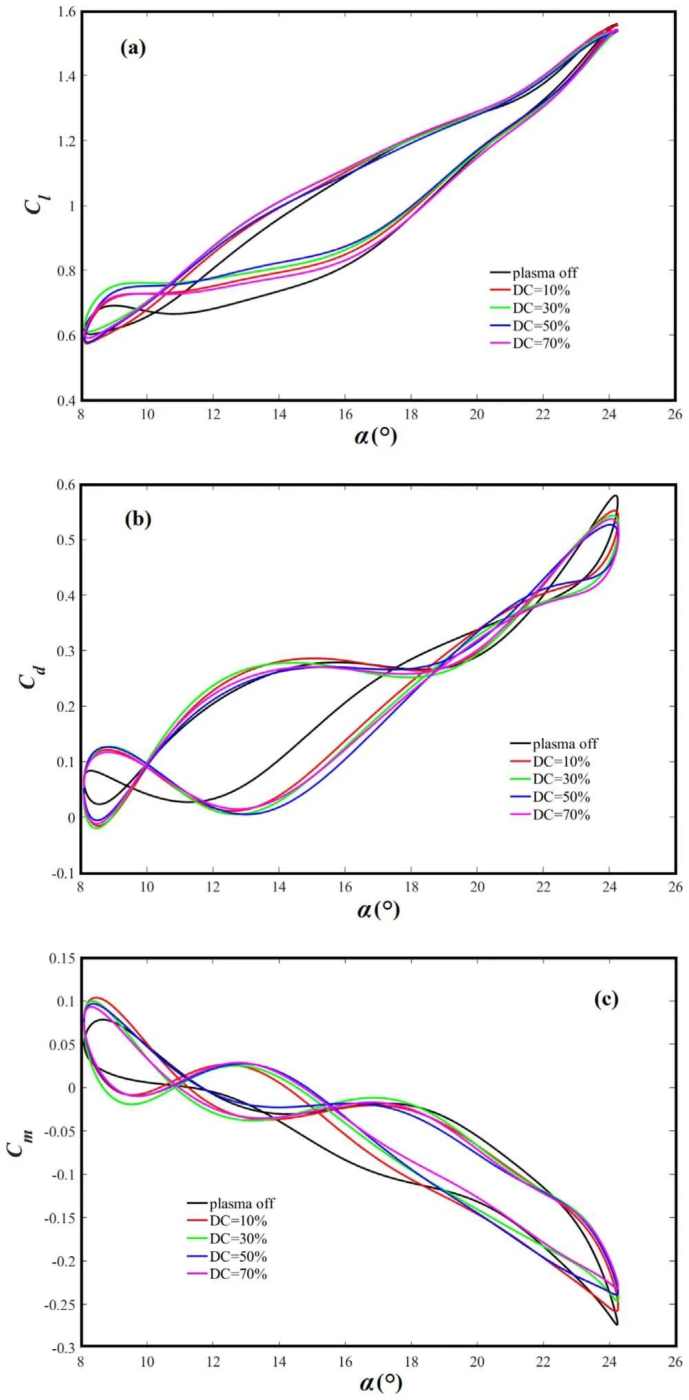
Figure 7.Experimental results of various duty ratios under unsteady actuation (Vp-p = 8 kV and F+ = 1).(a) Cl, (b) Cd, (c) Cm.
From the Clcurve, it can be seen that the difference of control effect obtained by actuation under different duty ratios is mainly reflected near the maximum α and in the latter part of the downstroke.In terms of peak lift, the curve after the actuation maintains the maximum lift of the baseline when the duty ratio is 10%;under the control of other duty ratios,small lift loss appears,which may be related to the strong impact of actuation on DSV.When the airfoil goes down to α = 19°,pulsed actuation can improve lift and reduce aerodynamic hysteresis; the control effects of DC = 30% and 50% are significantly better than those of DC = 10% and 70%.This suggests that a larger or smaller duty ratio is not the best choice.When DC = 50%, the area is maximally reduced by 24.8%;DC = 30%,10%and 70%respectively correspond to 22.3%, 19.8% and 18%.
The unsteady actuation also reduces the peak drag coefficient, similar to the steady actuation.With the increase of duty ratio, the drag reduction effect at the peak is more obvious.From α = 12° up to α = 19° on the upstroke, the drag reduction effect of actuation is significant,among which DC = 50% is the most prominent; it can reduce drag by 50.17% at α = 16°.However, in the process of the airfoil pitching up from the minimum α to α = 12°, the actuation has a negative effect on drag control.From the control results of drag coefficient, there is no significant difference between different duty ratios.
For the moment coefficient,under the control of different duty ratios,the peak moment coefficient is reduced;the rapid rebound of the moment can be observed at the beginning of the downstroke, and the greater the duty ratio is, the more obvious the improvement effect of moment is.Similarly, a negative effect is also obtained for moment control near the minimum α, which deserves further study.
In summary, there is an optimal duty ratio DC = 50%,which has the best effect in improving the aerodynamic characteristics of dynamic stall airfoil.The greater the duty ratio is, the better the control effect of the peak nose-down moment is.However,it should be noted that the author’s team has also conducted a lot of research on AC-DBD flow control[29], and obtained the influence law of unsteady actuation parameters, indicating that when the actuation position is located before the separation point, the control effect is obvious.Reducing duty ratio can reduce power consumption and improve the life of the actuator, while maintaining the same control effect.
Therefore, on the basis of static stall control, it is significant to study the influence of duty cycle on the effect of dynamic stall control.If a similar control effect can be achieved, the smaller the duty ratio, the smaller the power consumption.In the results obtained, DC = 30% and 50%achieve almost the same control results,but DC = 30%has a smaller duty ratio and lower power consumption,so it may be the preferred choice in practical application.
3.2.2.Flow control effect of different pulsed actuation voltages.Voltage is a parameter that characterizes energy injection.In plasma flow control, actuation voltage plays a significant role in effect, and currently the most important parameter of dynamic stall is not clear yet, so it is vital for conducting the flow control experiments of different actuation voltages.
The actuation frequency F+= 2 is kept constant and the duty ratio DC = 50% is maintained during the experiment,and four peak-to-peak voltage values are selected according to the tolerance of the actuator.Figure 8 presents the flow control effect of different Vp-p.
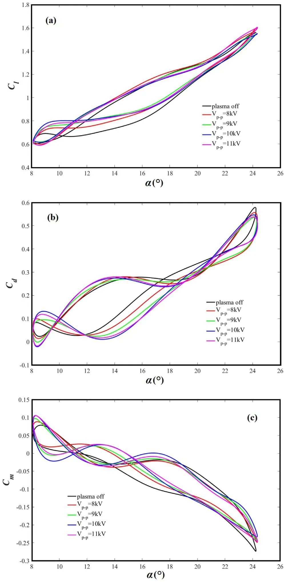
Figure 8.Experimental results of various pulsed actuation voltages(DC = 50% and F+ = 2).(a) Cl, (b) Cd, (c) Cm.
First of all, from the change trend of aerodynamic coefficients, the varieties still appear in the stage of high α and downstroke.Near maximum α, the peak lift coefficient is improved under the control of Vp-p= 8 kV and Vp-p= 11 kV.However, under the control of Vp-p= 9 kV and Vp-p= 10 kV,there is a small loss of lift, but this does not mean that the actuation will only produce negative effects.On the downstroke,when the airfoil goes down to a certain extent (α = 12°), the actuation starts to take effect again.The lifting effect corresponding to Vp-p= 9 kV and Vp-p= 10 kV is almost the most significant,and Vp-p= 11 kV is not inferior.The lifting effect of Vp-p= 8 kV is relatively poor.As the airfoil continues to go down,the advantage of large actuation voltage gradually appears,but larger does not mean better.At the stage near the initial α,the lift improvement effect of Vp-p= 10 kV is the best.From the analysis of improvement of lift hysteresis characteristics,the area of the hysteresis loop is reduced more significantly compared with the previous results.With Vp-p= 10 kV and Vp-p= 11 kV,it is reduced by 34.3%;with Vp-p= 9 kV,it is reduced by 32%,while for Vp-p= 8 kV condition, this value is only about 24%.So, if you just want to maintain and increase the lift at the maximum α, Vp-p= 8 kV is a very cost-effective choice, and it has the lowest energy consumption;however,if you also want to consider the lifting effect of the downstroke,Vp-p= 11 kV is the best option.
In terms of the drag coefficient, the range of angles of attack that appear to be controlled has changed; most of the angles of attack stroke of the upstroke and high angle of the attack stage have been controlled effectively,and only part of the angle of attack stroke has the effect of drag reduction on the downstroke.On the upstroke from α = 12° up to α = 20°, the greater the actuation voltage is, the more obvious the drag reduction effect will be,while in the process of α = 20° up to α = 23°, Vp-p= 8 kV and Vp-p= 9 kV have a better effect than Vp-p= 10 kV and Vp-p= 11 kV.As for the control of the peak drag coefficient, the peak is decreased after the application of actuation, and the peak control level of Vp-p= 9 kV, 10 kV, 11 kV is significantly higher than that of Vp-p= 8 kV.
The angle of attack range of the moment coefficient with control effect is similar to the drag coefficient.In particular,the large nose-down moment is controlled; when Vp-p= 10 kV, the peak moment coefficient is decreased the most,the peak moment control level of Vp-p= 8 kV is similar to that of Vp-p= 9 kV and Vp-p= 11 kV, and this indicates that Vp-p= 10 kV has the control advantage of improving the high nose-down moment.From α = 12°up to α = 19°of the upstroke, the actuation also reduces the nose-down moment,and the larger actuation voltage has a better effect.
In summary, the control effect of Vp-p= 9 kV, 10 kV,11 kV is significantly better than that of Vp-p= 8 kV,and the difference between the first three Vp-pis not large, which illustrates that there is a threshold of pulsed actuation voltage,and an obvious effect can only be achieved when the threshold is reached.If the voltage continues to increase on the basis of the threshold, no obvious control improvement will occur.
3.2.3.Flow control effect of different pulsed actuation frequencies.In terms of the static airfoil flow separation,pulsed plasma actuation separation control tends to have an optimal actuation frequency[30].Whether the optimal actuation frequency can be found in dynamic stall control needs to be further verified.Therefore, 8 dimensionless frequencies are chosen to explore this pattern.F+is defined as F+= f0c/U∞,where f0is the pulsed actuation frequency per unit time [8].
Figure 9 shows the control results with the airfoil’s motion profile ofα(t) = 16° + 8° sin(ωt)under various F+at k = 0.15.When dimensionless actuation frequency is changed, the actuation voltage and duty ratio are always maintained at Vp-p= 9 kV and DC = 50%.
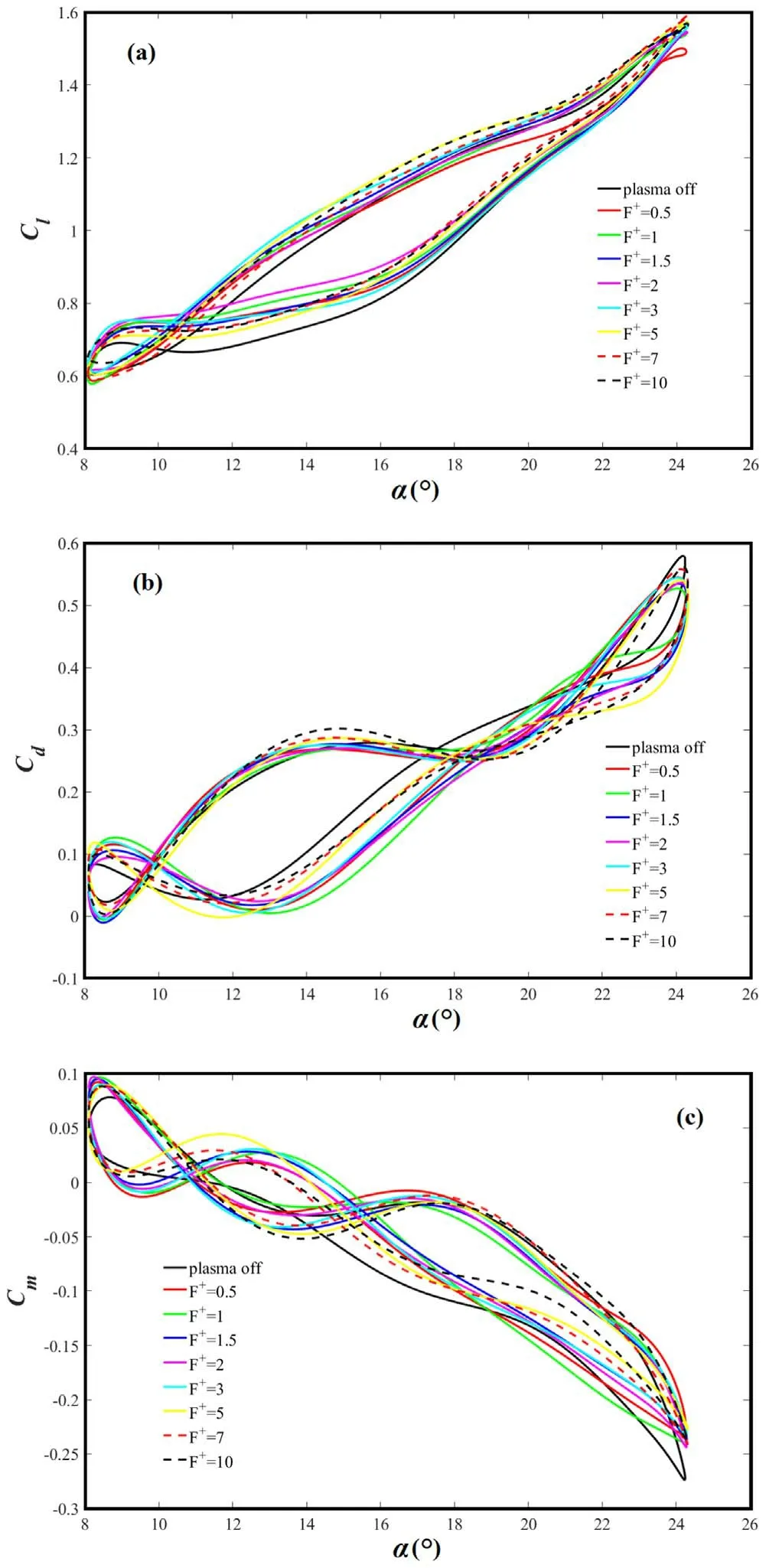
Figure 9.Experimental results of various pulsed actuation frequencies (Vp-p = 9 kV and DC = 50%).(a) Cl, (b) Cd, (c) Cm.
First, the trend is similar for various frequencies.Obviously, AC-DBD actuation under all actuation frequencies can make earlier reattachment, and the reduction in area of hysteresis loop is also observed.
On the upstroke, the lift coefficient under actuation is almost the same as the baseline, but when the airfoil reaches α = 18°, the curve controlled by F+= 0.5 actuation has obvious lift loss.This indicates that the flow field structure induced by F+= 0.5 actuation has an impact on the DSV,and the dynamic vortex lift force generated by the DSV is affected.However,some dimensionless frequencies can make up for this loss observed from figure 9, which indicates that the jet induced by a larger actuation frequency may promote the energy mixing between the boundary layer and the main stream to a greater extent, so as to make up for the lift loss caused by the impact on DSV.Through careful analysis of the peak value of lift coefficient at the maximum α, it is found that when F+≥ 5, the peak value under actuation is improved, but the amplitude is not large; the maximum increase is 2% at F+= 7.When F+≤ 2, there is a loss of peak lift, and it is most obvious when F+= 0.5.
At the beginning of the downstroke, most of the dimensionless frequencies have no lifting effect at first, and only F+= 5,F+= 7 and F+= 10 can improve lift slightly.When the airfoil continues to pitch down to α = 18°, at this point, the control effect of improving lift under all actuation frequencies is shown, and this kind of effect can be maintained to the minimum α.However, as the airfoil continues to go down, the effect with smaller F+is more obvious, especially F+= 2.F+= 2 has remained the first from α = 17°down to α = 8°;among them,when α = 12°,the lift coefficient can be increased by 18.16%maximum.By contrasting different F+, when the airfoil pitches down from 14°to 10°,the control effect of smaller F+(F+= 0.5,1,1.5 and 2)is obviously better than that of higher F+(F+= 3,5,7 and 10).In terms of the improvement of hysteresis characteristics, the area reduction of the hysteresis loop of lift coefficient under different F+is shown in table 1.
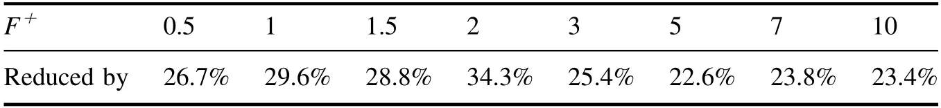
Table 1.Area reduction of the hysteresis loop of lift coefficient under different F+.
Therefore, unlike static stall control, it is hard to find a best dimensionless frequency for the entire pitch motion period of the airfoil, but rules can still be extracted from the control results; the high F+performs better in maintaining peak lift, and the low F+performs better in earlier reattachment on the downstroke and the improvement of hysteresis characteristics.
Different F+also get diverse control effects in aerodynamic coefficient control, which is mainly found in the control of the peak coefficients.Under actuation states,the large peak nose-down moment of the airfoil at the maximum α is reduced under all F+, which means less flutter, and the peak drag coefficient is also controlled, which indicates that the lift-drag ratio characteristics of the airfoil are improved to a certain extent.Table 2 shows the performance of different F+in controlling the peak drag coefficient and moment coefficient relative to the benchmark.
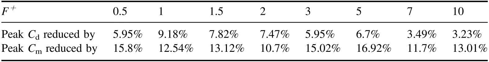
Table 2.Control results of peak drag coefficient and peak moment coefficient under different F+.
For drag and moment control,the trend law for the larger F+or lower F+is not obvious.The best dimensionless frequency can be found easily (F+= 1 in drag control and F+= 5 in drag control), but there is not much difference between different F+.Through comparison, an F+interval with better control effect can be obtained, which is more instructive.For drag control, this interval is F+= 1–2,whereas for large nose-down moment improvement, it is F+= 3–5.
To sum up, there is no optimal dimensionless frequency in dynamic stall control, but the control effect has regular laws.From the perspective of lift characteristics,different F+have different control advantages in different pitching stages and aerodynamic coefficient control, higher F+performs better in maintaining peak lift, and lower F+performs better in the improvement of hysteresis characteristics.For drag and moment, the effect of drag reduction and moment control with different F+is not significantly different, but a certain dimensionless interval with better control effect can still be found.
4.Discussion on control mechanism
4.1.Flow control effect analysis under AC-DBD actuation
It is generally believed that AC-DBD actuation mainly relies on volume force (Fb) effect to control the flow field in static stall control, as shown in figure 10 [31].
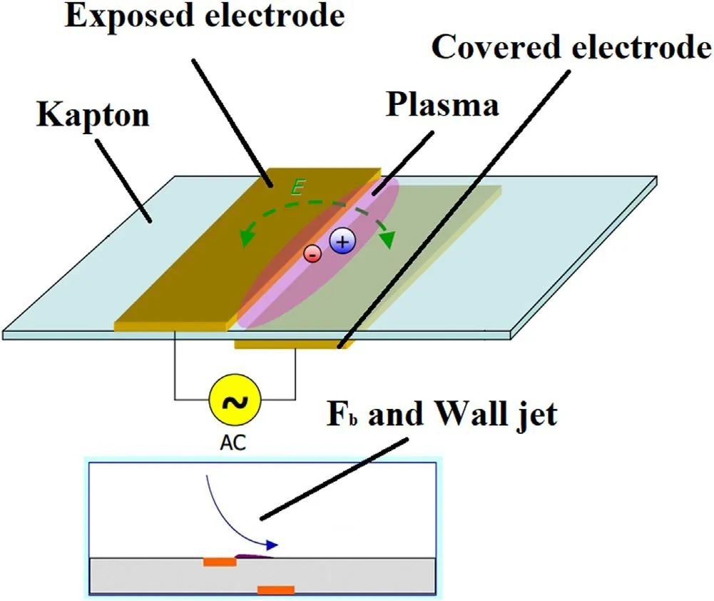
Figure 10.Working principle of AC-DBD actuator.
The steady AC-DBD actuation mainly induces the nearwall jet flow, while the unsteady AC-DBD actuation can induce periodic starting vortices under certain conditions(appropriate frequency and duty ratio).When the AC voltage is applied, the air over the surface of the actuator is ionized,and the charged particles move along the electric field under the action of the electric field force and collide with the neutral air gas molecules, thus inducing the directional movement of the airflow in this area to form a continuous jet [32, 33].
In the process of dynamic stall,the jet generated by ACDBD will inevitably affect the dynamic boundary layer,especially the interaction with the DSV’s formation and development over the airfoil, so the dynamic vortex lift is changed.However, if the plasma-induced jet is strong enough, such lift loss will also be avoided; this is why different combinations of actuation parameters achieve different results in peak lift control, such as in figure 9.The reduced frequency set in the experiment is k = 0.15,and the speed of the airfoil pitch oscillation is relatively fast, so the dynamic effect of the airfoil and its surrounding flow field must be considered.
During the upstroke,there is an airflow downwash effect,and the flow field structure induced by AC-DBD is more likely to be attached to the airfoil surface compared with the static airfoil, so the change of the flow introduced by actuation is small.Meanwhile, during the downstroke, due to the upwash effect induced by the airfoil’s oscillation,the plasmainduced jet will interact with the larger range of flow field structures above the airfoil.Under the influence of the actuation,the energy exchange between the main flow and the boundary layer is also more sufficient; naturally, the effect will also be maximized, so when the airfoil moves to the downstroke,the lifting effect of the actuation is reflected.The schematic process is shown in figure 11.
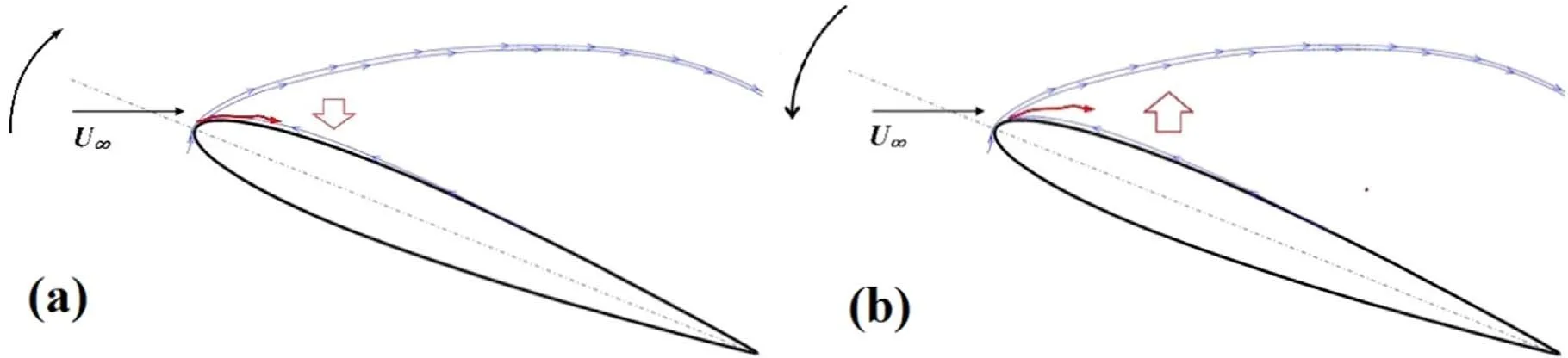
Figure 11.Control mechanism of AC-DBD actuator.(a) Upstroke.(b) Downstroke.
4.2.Comparison of steady and unsteady actuation
In this paper, both steady actuation and unsteady actuation have achieved some certain control effects.However, for dynamic stall control,which one has more control advantages still needs further quantitative comparison.
The changes of peak lift coefficient (a%), lift hysteresis loop area (b%), peak drag coefficient (c%) and large nosedown moment coefficient (d%) are shown in table 3.
By comparison,except for the large nose-down moment,the unsteady actuation has obvious control advantages in the other three indicators.The other three indicators can be summarized as the embodiment of the changes of lift and hysteresis.The steady actuation also has its merits; it can better alleviate the oscillation caused by the large nose-down moment.This point can also be confirmed in section 3.2.1.Among the four alternative duty ratios of DC = 10%, 30%,50% and 70%, the greater the duty ratio is, the better the control effect of the peak nose-down moment will be.
In order to explore the control effects of different discharge modes,the characteristics of Fband induced flow field under static condition are tested in speciality.The Fbtest was performed at duty ratio DC = 50% and F+= 2.Figure 12 shows the Fbgenerated by the unit length DBD actuator under different actuation voltages.
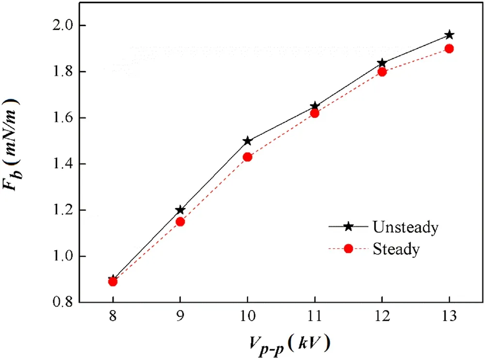
Figure 12.Fb per unit length under different voltages by AC-DBD actuation.
It is obvious that the larger Vp-pis, the larger Fbper unit length is, and the Fbof unsteady actuation is more obvious under the same Vp-p.When Vp-p= 13 kV, the Fbper unit length generated by unsteady AC-DBD actuation reaches 1.96 mN m?1.
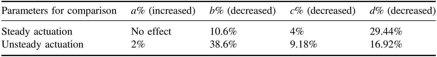
Table 3.Comparison of control results between steady and unsteady actuation.
At the same time, the particle image velocimetry was used to obtain the induced flow field.First, the steady actuation was studied under Vp-p= 12 kV.The starting time of the discharge was recorded as t = 0 s, and the actuator position was located at x = 20 mm.In the initial stage of actuation (about t = 0.3 s), a start-up vortex will be induced.When it is close to t = 3 s, the induced vortex structure will finally evolve into a near-wall jet.Then at Vp-p= 12 kV, the unsteady actuation test is carried out at F+= 2 (fp=200 Hz); results are shown in figure 13.
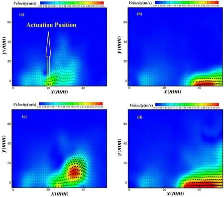
Figure 13.Flow induced by steady and unsteady AC-DBD actuation.(a) Start-up vortex: steady actuation, t = 0.3 s.(b) Wall jet: steady actuation, t = 3 s.(c) Start-up vortex: unsteady actuation, t = 0.3 s.(d) Wall jet: unsteady actuation, t = 3 s.
Comparing the changes of velocity and vorticity induced by the actuation, it is found that the instantaneous action intensity of the unsteady actuation is greater, and the acceleration ability of the induced flow field is stronger.The steady actuation mainly relies on the induced wall jet to exert an influence on the flow field, and the disturbance imposed on the flow field at the beginning of the discharge is small;while for the unsteady actuation, the induced velocity and vorticity in the start-up vortex phase are larger, indicating that the instantaneous effect of the unsteady actuation is more obvious, and the actuation intensity in the initial phase is greater than the stable stage [2].
According to results in figures 12 and 13, it can be concluded that the flow control ability of unsteady actuation is stronger than that of the steady mode.In our previous paper,the LES model is used to solve the flow field after applying unsteady AC-DBD actuation [34].
The simulation results show that the AC-DBD actuation generates a short volume force accelerated disturbance,which promotes the increase of the attached vortex energy at the leading edge of the airfoil, and the vorticity increases, which will move downstream from the leading edge, and finally dissipate in the turbulence of the downstream.The leading edge vortices that fall off in this process induce the separated flow to move to the airfoil surface,making the near-wall area streamlined, and the air flow flows along the upper airfoil,thereby inhibiting separation and improving lift characteristics of the airfoil.
AC-DBD actuation not only accelerates the boundary layer, but also induces vortices locally in the flow field, and the unsteady actuation can induce stronger vortices locally.The vortex’s disturbing effect can enhance the mixing of mass and energy in the boundary layer and between the low-energy flow of the boundary layer and the high-energy flow of the mainstream.
More energy of the mainstream is introduced into the boundary layer.By injecting new energy into the boundary layer, the flow velocity is increased, and low-energy airflow accumulation is reduced, effectively preventing the boundary layer separation; naturally, the control effect of restraining and slowing the separation of the boundary layer and increasing the lift and drag reduction is achieved.Therefore,the unsteady actuation performs better in improving the dynamic airfoil’s aerodynamic performance.
For the advantages of steady actuation in improving the peak nose-down moment,analysis and inference can be tried,but this needs to be further validated.
The reason is that the unsteady actuation is bound to interact with DSV more fully.While supplementing the dynamic vortex lift, it can be equivalently considered to strengthen the intensity of DSV from the perspective of the microscopic flow field.The greater the strength of DSV, the greater the nose-down moment.Therefore, its poor effect in moment control is the result of the combined effect of strengthening the DSV and injecting energy into the boundary layer.Another reason is that referring to the conclusion drawn in the static characteristics test,the unsteady actuation is more of the instantaneous pulsed effect, and the change of the instantaneous moment without sustain-time accumulation may not be reflected in the final moment coefficient,so steady actuation can be more effective in moment control.
4.3.Discussion on control effects of different F+ in unsteady actuation
According to the experiment results, it is hard to find an optimum actuation frequency.Different F+have different control advantages in different pitching stages and aerodynamic coefficient control.This is interesting and deserves further discussion.
Hiroaki Fukumoto carried out the high-precision numerical simulation study of airfoil dynamic stall controlled by AC-DBD actuation [35, 36].What is surprising is that his simulation results can echo the macroscopical control results obtained in this paper.The research of Hiroaki Fukumoto was also carried out under the condition of the order of Reynolds number of 105and three dimensionless parameters of F+= 0.5 and F+= 6 were studied respectively; the choice of these three F+is a good representation of higher F+and lower F+, and can also correspond to the dimensionless parameters selected in the experiment.In our current paper,similar aerodynamic coefficient control effects were obtained.
There are four main similarities.First,under control of all actuation frequency, the plasma actuation at the small α stroke in the pitch-up phase has no control effect.Second, in the high α stall phase, the high frequency actuation achieves better effect of maintaining lift or increasing lift.Third, the low-frequency actuation has achieved a better lift recovery effect after entering the pitch-down phase.Fourth, high frequency actuation has achieved better results in drag and nosedown moment control.
The flow field structures corresponding to the higher and lower dimensionless frequencies are analyzed in depth in[35, 36].Such high-precision simulation results are helpful for analysis.
Regarding the first point,as mentioned in section 4.1,the AC-DBD plasma actuation has a range of capabilities and it has no effect at the small α where the leading edge does not separate.Reference [35] observes that a laminar separation bubble has not formed yet so that plasma actuation cannot gain effect.But here, regarding the conclusion that the optimal actuation frequency is not found in the dynamic stall control, we have to talk about the physical mechanism of static stall and dynamic stall.
In the static stall, when the angle of attack of the airfoil increases to near the stall angle,there is serious separation of the airflow on the upper airfoil near the stall angle,and the separation zone spreads from the trailing edge forward and gradually extends to the top half of the airfoil.In this case, the plasma actuation continues to inject energy into the boundary layer, so that within the actuation frequency range studied, an optimal actuation frequency can be found and the lift-drag characteristics of the airfoil can be improved to the maximum extent.
However,the physical evolution process of dynamic stall is different [37].The flow display method and numerical simulation have revealed the general evolution process of fully evolved dynamic stall of the airfoil under normal pitch conditions.Figure 14 shows the flow field evolution process within a pitching period T of the airfoil obtained by calculation and simulation under the condition of reference to the experimental baseline flow.During t = 0–T/8, the airfoil starts to rise from the average angle of attack, and no boundary layer separation occurs at the leading edge during the period.When t = 2T/8, the airfoil is raised up to the maximum α.With the formation of the leading edge vortex,the flow in the boundary layer begins to reverse and gradually leads to large-scale flow separation.Meanwhile, the leading edge vortex flows along the chord, generating additional lift force.When t = 3T/8, the airfoil starts to pitch downward from the high α,and vortex detachment occurs at the leading edge, which not only causes the loss of lift force, but also causes the sharp change of pitching moment.t = 4T/8–6T/8 means that the airfoil continues to lower its head after the average angle of attack,and the whole process is a process of flow reattachment.During this period, although the α is reduced, the effective α of the airfoil is still large due to the upwash flow caused by the pitch-down motion,and the whole upper part of the airfoil remains in a separate state.After t = 7T/8,the airfoil begins to lift up,and the downwash flow begins to act.The effective α is small,and the flow separation on the upper surface is relieved.At the same time, the α gradually increases from small α, and the lift force slowly recovers.When it reaches the position of the average α, the motion within a pitching cycle is completed.
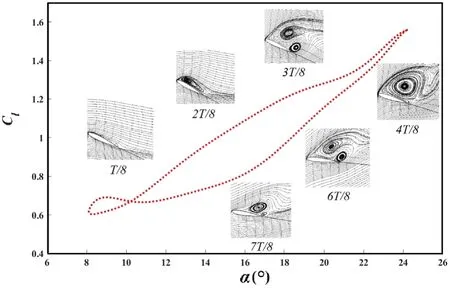
Figure 14.The flow field at different moments of a pitching cycle combined with baseline lift curve [38].
It can be concluded that the sign of the dynamic stall phenomenon is the emergence of the leading edge detached vortices.With the pitching up of the airfoil, the detached vortices move rapidly to the bottom of the airfoil,which will cause a large bow moment acting on the airfoil.Because of the dynamic effect, the stall α of the oscillating airfoil is generally larger than the static stall α in the same flow field environment,and the maximum lift force increases.However,once the stall α is exceeded,the formation and movement of DSV will lead to a very complex flow phenomenon,resulting in a sharp drop in lift force and a large peak of drag and nose-down moment.Especially, the greater the intensity of the DSV, the more seriously the aerodynamic characteristics of the airfoil deteriorate.
As we know, for a static airfoil’s separation control, the actuation’s control effect extensively depends on the airfoil’s α, and the stall can only be delayed by 2–3 degrees [9].This means that the plasma actuation has a range of capabilities,and it has no effect at the small angle of attack where the leading edge does not separate and the high α is much larger than the stall α.
It can be concluded that, if there is an optimal actuation frequency in the upstroke of the airfoil, the dynamic vortex lift force can be well maintained and the structure of the dynamic stall vortex can be damaged to a small extent.However, in the steep stall stage, the damage caused by the dynamic stall vortex will appear, and the flow field in the downstroke will be more complex.If a certain actuation frequency is not effective in maintaining peak lift, it means that its impact on the dynamic stall vortex is relatively severe.In contrast, it is easier to control the flow field structure after a stall at this frequency.Therefore, dynamic stall is a stage where the upstroke and downstroke phases check and balance each other and influence each other.Its control has the feeling of losing the other if one is controlled.Therefore,the coupling of the dynamic stall complex flow field and a certain actuation frequency is difficult to obtain both ‘best’ effects.
In addition,[36]showed that the case of F+= 0.5 shows a large vortex during the dynamic movement of the airfoil,and the series of flow patterns shows the growth of a vortex emanates from the leading edge shear layer induced by the AC-DBD plasma actuation.In the case of F+= 6, the leading edge shear layer is also affected by the AC-DBD actuation,the leading edge shear layer is cut into some parts.Here,the case with the faster increase in CLis the case of F+= 6.Considering that the case of F+= 6 improves CDmore,whereas this case can delay the dynamic stall onset, it is inferred that a large portion of the improved CDin the case of F+= 6 owes much to this effect [36].
In the study of flow separation control, our previous research concludes that pulsed-DBD actuation can inspire K-H instability of the shear layer at the leading edge shear layer, so that the jet or vortex structures induced by pulsed-DBD actuation can continue to grow with the moving downstream [8].F+may determine the scale of disturbance over the wing surface [39, 40].The span-wise vortices induced by actuation at low F+can be developed into largescale attached vortex structures [8].When actuation is under high F+, the large-scale vortex may not be formed, and it is mainly the small-scale span-wise vortices that play a role in the flow control.When the small-scale vortices move downstream, the adjacent vortices will get closer.Once they are close enough,they will merge together[8,41].Comparing the simulation results of Hiroaki Fukumoto, it can be concluded that in the process of dynamic stall, the vortex structure induced by AC-DBD at different frequencies has similar laws as in the static flow field.At high F+, the leading edge shear layer is cut into some parts;this makes the AC-DBD actuation inject more energy into the dynamic boundary layer[35,36],which ultimately leads to the high frequency actuation achieving a better effect of maintaining lift or increasing lift;and high frequency actuation has achieved better results in peak drag and nose-down moment control.
The high-precision simulation results of Samimy M and Visbal M R et al [42–46] have also obtained similar control effects, and they explained the physical characteristics of the flow from the perspective of DSV movement.Samimy M holds that at a high angle of attack stall phase,the action of the adjacent span-wise vortices induced by low F+actuation cannot be merged.This means that the control ability of low F+actuation is insufficient near the maximum α.At the same time,the dynamic vortex lift is weakened,resulting in a drop in the peak lift coefficient.Meanwhile at high F+actuation cases,the newly formed closely spaced structures can damage and even replace the natural DSV structure, greatly reduce the intensity of DSV and strongly promote the mixing of momentum and energy between the boundary layer and the main flow, making the turbulence of the leading edge flow higher.This allows the dynamic stall to be alleviated and makes up for the loss of lift due to damage to the DSV[42,43].
Visbal M R points out that, interestingly, the corresponding flow structures induced by AC-DBD continue to play a role in the downstroke phase.The formation of large coherent structures induced by low frequency actuation entrains high-momentum flow from the freestream and results in reattachment.The formation of small structures produced by high frequencies only results in partial reattachment[44–46],this is a good illustration of the control effect that the low-frequency actuation has achieved a better lift recovery effect after entering the pitch-down phase.
It should be noted that the above content is a mechanism discussion based on the macroscopical control results, combined with the plasma actuation characteristics and the simulation results of others.Although the experimental results of this paper can be well reflected in previous studies, the work done by everyone is only under the flow field in a certain state,and the internal mechanism may also be related to factors such as dynamic stall degree and Reynolds number, so the actual flow field evolution process needs further experimental verification.
Finally,it is important to note that the above explanations are based on the condition that the actuator is always on during the airfoil movement, and for an actuation state, the actuation parameters will not change after the actuator is on.In static stall control, there is an optimal unsteady pulse actuation frequency for a specific airfoil and α.In order to take into account the control effect of the whole pitch process in dynamic stall, frequency conversion control at different angles of attack stages is needed,which is the significance of obtaining the parameter law.The so-called optimum actuation frequency is not absolute and one actuation frequency may be the best in improving the characteristics of the lift-drag ratio,but it cannot be called the best in other aspects such as vibration reduction and noise reduction that have not been completely accurately measured.
5.Conclusion
In the past decade,the AC-DBD actuation has been verified in the control of dynamic stall at low speed conditions,while the ability for the dynamic stall control under higher freestream velocity and larger reduced frequency has not been proven.
Therefore, the dynamic stall wind tunnel experiments of the SC-1095 airfoil controlled by AC-DBD actuation were carried out and the control effectiveness under steady and unsteady actuation at k = 0.15 and U∞= 30 m s?1was verified and quantitative comparative study was completed forα(t) = 16° + 8° sin (ωt).The influence of actuation voltages for steady actuation (constant Vp-p= 8–10 kV) and pulsed actuation voltages (Vp-p= 8–11 kV), frequencies(F+= 0–10), duty ratios (DC = 10%–70%) for unsteady actuation on dynamic stall control effect was studied.Corresponding control laws are summarized and the control mechanism is discussed.The main conclusions are as follows.
(1) Under the condition of U∞= 30 m s?1and k = 0.15,the steady actuation can reduce the area of the hysteresis loop of airfoil’s dynamic lift, and also can effectively control the peak drag and nose-down moment coefficient.With actuation voltage Vp-p=10 kV, the area of hysteresis loop can be reduced by 10.6%, the peak drag coefficient can be reduced by 7.3%, and the peak value of the large nose-down moment can be reduced by 29.6%.
(2) For unsteady actuation, there is an optimal duty ratio DC = 50%, which has the best effect in improving the lift and drag characteristics of the dynamic stall airfoil,and the greater the duty ratio is, the better the control effect of the peak nose-down moment is.A threshold of pulsed actuation voltage can be found,and best control effect can be achieved only when the threshold is reached.If the voltage continues to increase when the voltage is above the threshold value, no more obvious control improvement will be obtained.
(3) We cannot conform the optimal dimensionless frequency in dynamic stall control.Different F+have different control advantages in different pitching stages and aerodynamic coefficient control,higher F+performs better in maintaining peak lift, and lower F+performs better in the improvement of hysteresis characteristics; meanwhile, the effect of drag reduction and moment control with different F+is not significantly different,but a certain dimensionless interval with better control effect can still be found.
(4) By quantitative comparison, the unsteady actuation has obvious control advantages in improving the lift-drag characteristics and reducing the area of the hysteresis loop,while the steady actuation also has its merits, and can better alleviate the oscillation caused by violent nose-down moment.
Acknowledgments
The work of this research is supportedby the China Foundation Enhancement Fund (No.2019-077), National Natural Science Foundation of China (No.11802341) and Research Project of Academician and Expert Workstation of the Green Aerotechnics Research Institute of Chongqing Jiaotong university (No.GATRI2020C06003).Thanks to Wei Biao, Xie Like, Lin Muyang, Zhao Guoqing and Jia Yuhao for their help in the experiments.
ORCID iDs
猜你喜歡
Chinese Physics B(2023年9期)2023-10-11 07:56:02
Chinese Physics B(2022年10期)2022-10-26 09:54:30
科海故事博覽·上旬刊(2022年5期)2022-05-17 16:17:01
Chinese Physics B(2022年5期)2022-05-16 07:12:20
Chinese Physics B(2022年5期)2022-05-16 07:12:16
科學(xué)家(2022年4期)2022-05-10 03:47:14
Chinese Physics B(2022年1期)2022-01-23 06:35:18
知音海外版(上半月)(2019年7期)2019-01-10 06:57:30
Acta Mathematica Scientia(English Series)(2018年5期)2018-11-22 09:24:04
速讀·下旬(2017年4期)2017-06-20 17:51:03
 Plasma Science and Technology2021年11期
- Plasma Science and Technology的其它文章
- Influence of magnetic filter field on the radiofrequency negative hydrogen ion source of neutral beam injector for China Fusion Engineering Test Reactor
- Investigation on current loss of high-power vacuum transmission lines with coaxial-disk transitions by particle-in-cell simulations
- A low-jitter self-triggered spark-discharge pre-ionization switch: primary research on its breakdown characteristics and working mechanisms
- A calculation model for breakdown time delay and jitter of gas switches under hundred-nanosecond pulses and its application in a self-triggered pre-ionized switch
- Study of tetracycline removal and saturated resin regenerated by dielectric barrier discharge plasma
- Experimental study on the parameter optimization and application of a packed-bed dielectric barrier discharge reactor in diesel particulate filter regeneration