
Hardware for multi-superconducting qubit control and readout*
2021-11-23 07:24:14ZhanWang王戰(zhàn)HaiYu于海RongliLiu劉榮利XiaoMa馬驍XueyiGuo郭學儀ZhongchengXiang相忠誠PengtaoSong宋鵬濤LuhongSu蘇鷺紅YirongJin金貽榮andDongningZheng鄭東寧
Chinese Physics B 2021年11期
關(guān)鍵詞:東寧
Zhan Wang(王戰(zhàn)) Hai Yu(于海) Rongli Liu(劉榮利) Xiao Ma(馬驍) Xueyi Guo(郭學儀)Zhongcheng Xiang(相忠誠) Pengtao Song(宋鵬濤) Luhong Su(蘇鷺紅)Yirong Jin(金貽榮) and Dongning Zheng(鄭東寧)
1Institute of Physics,Chinese Academy of Sciences,Beijing 100190,China
2Beijing Academy of Quantum Information Sciences,Beijing 100193,China
3Beijing Liuhe Lianchuang Technology Co.,Ltd.,Beijing 100011,China
4University of Chinese Academy of Sciences,Beijing 100049,China
5Songshan Lake Materials Laboratory,Dongguan 523808,China
Keywords: superconducting qubit, dispersive readout, arbitrary-waveform generator (AWG), analog-digital converter(ADC)
1. Introduction
Superconducting qubits as a promising solution for quantum computing is developing towards intermediate scale processors that consist of tens of qubits.[1,2]To characterize and perform research with these processors, the ability of control and readout of multiple qubits is essential. Furthermore, it is suggested that to realize a logic qubit a large number of physical qubits is needed,according to the error rate achieved currently. In this regard, not only control and readout of many qubits is essential, but also the used hardware requires good scalability, high synchronization and low latency. Moreover,in order to achieve fault-tolerant quantum computing, active quantum error correction of qubits is inevitable.[2-4]Some progress has been made in this direction.[5-7]For fault-tolerant quantum computing, high fidelity gate operations that meet the expected fault-tolerant threshold must be achieved and the feedback control time should be less than one percent of the decoherence time.[11]This means high accuracy in qubit control and low feedback latency are required.[8]
There have been a number of reports on the literature to describe multi-qubit control and readout systems.[9-12]
In this paper,we report our efforts in developing an electronic hardware system for the purpose of control and readout of multiple superconducting transmon qubits.We demonstrate the functionality of the hardware system by applying it to control and readout a 10-qubits device.
2. Basics of control and readout of superconducting transmon qubits
Superconducting qubits are designed to have energy level spacing around 5 GHz. To control the qubit state,microwave pulses with appropriate frequency, amplitude and phase are needed.The standard method is to define the pulse shape using anIQmixer. In-phase and quarture control signals are generated by AWGs. With theIandQsignals,the microwave signal from a microwave source can be modulated into a pulsed signal with desired frequency, phase and shape. For energy level tunable qubits, one may apply a fast or a slow DC bias to change the qubit energy level spacing. Thus, in order to control one qubit, three AWG channels (two forIQcontrol and one for fast bias control) and one DC bias channel are needed. For multi-qubit control,the number of AWG and DC bias channels should increase accordingly.
The readout of transmon qubits is realized by the dispersive readout scheme.[14]The underlying physics is the coupling interaction between a resonator and a two-level atom(or qubit), being well understood in quantum optics. When the frequency detuning?, difference between the resonator frequencyωrand the qubit frequencyωq, is much larger than the coupling rateg, the system is in the so-called dispersive coupling regime. In this case,the transition of the qubit from the|0〉state to the|1〉state would lead to the change of the resonant frequency. In other words, detecting the qubit state is realized by observing the shift in the resonant frequency of a readout resonator interacting with the qubit. Apart from its nondestructive nature, another advantage of the dispersive readout scheme is that it can be easily adapted into multiplex readout form. In a multi-qubit device,each qubit is coupled to a readout resonator. The readout resonators are also coupled to a microwave transmission line and the resonant frequency of each resonator is made slightly different from others. In such an arrangement,one can detect a qubit by measuring the amplitude or phase change of the corresponding resonator.
The electronic hardware for one readout channel includes a microwave source,two AWGs and a data acquisition board.The AWG signals mix with microwave signal via anIQmixer to form readout pulses that contain frequency values corresponding to the resonant frequency of each readout resonator.The readout pulses are then sent to the readout transmission line on the quantum chip. The signals from the chip are amplified and demodulated by the same local microwave signal via anotherIQmixer. The demodulatedIQsignals are acquired by the data acquisition board and processed either by on-board microprocessor or a computer. Usually,one readout transmission line can be used for detecting about ten qubits.
In Fig. 2, schematics of experimental setup for multiqubit system is shown. The dilution refrigerator provides a milliKelvin low temperature environment. The control and readout hardware units are connected to the device via microwave coaxial cables, with attenuators and filters being inserted at different low temperature stages for each line to reduce external electromagnetic interference.
From the above description, we can see that multichannel AWGs and DC bias sources together with data acquisition board are essential for the control and readout of multiqubit quantum chip.
3. Design consideration
Scalability To achieve good scalability of the system,we intentionally modularize the specific readout, control and other hardware functions. This means we can easily expand the system for more qubits. In our modularized hardware system,there are core board,clock board,readout board,control board and bias board.Each type of boards provide corresponding functions of qubit control and readout. We consider two kinds of scalability requirements. One is scalability within the chassis. If a new module (such as microwave AWG module)is needed, we can directly insert the corresponding modular board to the chassis, without considering its power supply,clock, trigger and other issues. Another one is the scalability between the chassis. If we need more and more readout and control hardware, we can link multiple chassis together through clock and trigger connections,which can ensure various chassis work together orderly.
Synchronization High synchronization between different control channels is required to ensure accurate manipulation of qubit quantum state, and thus to reduce error accumulation. In our system,different module boards in a chassis are controlled by the same clock board, which distributes its high-frequency clock and trigger signals to other boards. In addition, the system can accept external reference clock and trigger signals to ensure the synchronization of different chassis.
Latency The latency in qubit control and readout is mainly limited by three factors. The first one is the data transmission time between the master computer(usually a PC)and the slave computer as well as the time between the slave computer and FPGA. The following two methods are adopted to reduce this data transmission time. (i) Using direct memory access (DMA) transfer technology to improve the communication efficiency between the master and the slave computers.(ii)Instead of transferring all data to the master computer for data demodulation process,data acquired by the ADC are demodulated by the on-board FPGA of the readout module.
The second limiting factor is due to the board control time. In other words, there is a response time for boards to store and execute after receiving a string of commands.When more than one boards are in use,we implement an asynchronous parallel control strategy in the program to reduce the module waiting time.
The third limiting factor of latency is related to the feedback control.To realize quantum feedback,the received signal from qubits should be processed first and then send commands to the AWGs to generate control signals.In order to reduce the time delay, we integrate the AWGs and ADCs on one board and thus they are controlled by the same FPGA.The time required for ADC data acquisition to data processing, and then to AWG output can be optimized within one FPGA clock cycle.
4. Details of hardware
Figure 1 shows the photograph and schematic diagram of our hardware system. The system is mounted in a VPX-6U chassis. VPX motherboard in the chassis provides the power supply,communication hardware and RF connectors for each utility board.Up to 10 different types of boards can be inserted into this chassis. As shown in Fig.1(b),all boards communicate with the core board by peripheral component interconnect express (PCIE) bus. In the whole hardware system, the core board acts as the slave computer,which can be remotely controlled by the master computer. The function of clock board is to provide standard clock and trigger signals for other boards.
The core board is a microcomputer with an Intel i75850EQ processor. All boards communicate with the core board through the bus switch (as shown in Fig. 1(b)) by the PCIE protocol. The core board communicates with the external measurement system through gigabit ethernet via User Datagram Protocol(UDP).
The clock board is composed of an FPGA chip(XILINX XC7K325T),a low-noise broadband RF phase-locked chip(TI LMX2592)and other auxiliary hardware. The clock board accepts an external 10 MHz clock and an external trigger for synchronization between chassis. The function of the clock board is to provide standard clocks and different adjustable trigger signals for other boards. For example, the clock board provides a 1.25 GHz clock to the ADC chip,a 2.5 GHz clock to the digital-analog-converter(DAC)chips,and a low-frequency clock to the DC board.

Fig. 1. (a) Photo graph of the hardware system. This chassis is a VPX-6U chassis. (b)Schematic diagram of the hardware system.

Fig.2. Schematic experimental setup for superconducting multi-qubit systems.
The clock board is composed of an FPGA chip(XILINX XC7K325T),a low-noise broadband RF phase-locked chip(TI LMX2592)and other auxiliary hardware. The clock board accepts an external 10 MHz clock and an external trigger for synchronization between chassis. The function of the clock board is to provide standard clocks and different adjustable trigger signals for other boards. For example, the clock board provides a 1.25 GHz clock to the ADC chip,a 2.5 GHz clock to the digital-analog-converter(DAC)chips,and a low-frequency clock to the DC board.
The primary function of the readout board is to readout the quantum state of qubits. The readout board consists of two ADCs and two AWGs. As described in Section 2, the AWGs are used for the modulation of readout microwave signals and the ADCs are used for data acquisition. In addition,this board can also perform fast quantum feedback control.The FPGA on the readout board can simultaneously control the ADC and DAC to achieve fast feedback.The readout board is composed of an FPGA chip (XILINX XC7V690T), two DAC chips (LINEAR LTC2000IY-16), two ADC chips (TI ADC12D1800RF) and other peripheral auxiliary hardware.The DAC chips,as the same as used in the control board,function as two AWGs. The signal acquisition is performed by using two ADC chips with±1 V input voltage range, 12-bit resolution and 1.25 GHz sampling rate.
The control boards are actually AWG boards. Each control board is composed of an FPGA chip (XILINX XC7V690T-2FF1761I), 6 DAC chips (LINEAR LTC2000IY-16) with 16-bit resolution and 2.5 GHz sampling rate, and other auxiliary chips. It is able to generate 6 channels of independent AWG signals with 16 bit resolution,600 MHz bandwidth and±1 V output voltage range. As shown in Fig. 2,the AWG signals are used to control qubit by modulating amplitude,frequency and phase of a microwave signal via anIQmixer. The modulated microwave pulses control the operation of the qubit in theXYdirection. Additionally, the AWG signal can also be used to generate a fast-changing waveform to directly control the qubitZbias to realize the gate of the qubit in theZdirection.
The bias board is composed of an FPGA chip (XILINX XC7k325t),16 DAC chips(TI DAC5682Z)and related auxiliary hardware. The board provides 16 channels±10 V of DC voltage output with 20-bit resolution. As shown in Fig.2,the function of the bias board is to provide a DC bias for changing qubit working frequency to find a suitable operation and readout point. Additionally,the board can also be used to control the microwave switch,which can further reduce unwanted microwave leakage to the qubits and improve the control fidelity.
4.1. Waveform generation
In order to provide flexibility in operating the system at the different stages of experiments, we design two different waveform generation modes,namely,the direct mode and the sequence mode. The two waveform generation modes are shown in Fig.3.
In the process of the direct mode,the DMA transfers data to FPGA,and FPGA loads it to AWG.Finally,the AWG generates waveforms. Although this method may cost more time for data transmission between components, it is simple and flexible to use during experiment preparation and test stage.

Fig.3. Logic diagram for waveform generation. Two output modes of AWG are designed.
In the sequence mode,we construct 64 memory units inside the FPGA.Each of the units consists of waveform information related to the id number, play settings and data. The information stored in the memory units can be recalled, arranged and compiled into a waveform in accordance with the requirement of quantum operations in experiments. For instance, a qubit gate operation waveform can be stored inside a sequence memory unit and the arrangement and compile of these sequence is equivalent to the operations of the entire experimental Hamiltonian. In this way, once the waveforms of the various gates are determined,we can control the entire operations with predetermined combination of the gates.
4.2. Multi-qubit demodulation
According to Section 2, theIQdata can be collected and demodulated by readout board to get information of qubit state.One may transmit all theIQraw data to master computer and perform data process,or use the FPGA to do it on-board.Obviously, the latter can reduce the latency of data transmission and processing, being beneficial to quantum feedback function.
In quantum experiment,the data size is huge and the network communication between the master and slave computer is a time-consuming task. Realizing demodulation in FPGA can drastically decrease the time of data transmission. For instance, for one readout, 4096 16-bit data could be captured 2000 times by ADC.After the FPGA demodulation,only one 16-bit qubit state data needs to be transmitted and the whole data volume is reduced by 4096×2000 times, which greatly reduce the data transmission time.
The demodulation algorithm in FPGA can be traced back to Fourier transform

Here,the summation is over the time domain of data acquisition.
As shown in Fig. 4(a), the demodulatedIandQdata of the|0〉and|1〉states can be displayed on theI-Qplane. The blue and orange dots are taken when the qubit is set at|0〉and|1〉states, respectively. Due to decoherence and noise, some of the orange dots are located in the blue cloud,and some blue dots appear in the blue cloud.

Fig.4. Schematic diagram of qubit state rotation in IQ plane,before(a)and after(b)rotation.
Therefore, the qubit state can be distinguished in FPGA by following operations.Firstly,we demodulate qubitIQdata,mark it on theI-Qplane and calculate the angle between the central axis of the two states and in-phase axis. According to the angle, we rotate the data so that the central axis of two clouds is parallel to the in-phase axis, as shown in Fig. 4(b).We can set a threshold between the two clouds for deciding the qubit state. After obtaining the rotate angle and the best threshold, these parameters can be used to distinguish subsequent qubit state. The corresponding algorithm steps in FPGA are shown in Fig.5 schematically.
For readout of a multi-qubit device,each qubit can be demodulated by its own frequency. When measuringkqubits at the same time, the measured state is one of 2kpossible states.We can express the state using a binary number(such as 1010110100 for ten qubits)and assign it as the address of the registers in the FPGA.When this binary number appears once,the register will count once. Therefore, if we repeat readout measurementNtimes,and the same binary number appearsntimes,the register will countntimes. Then,the probability of the state isn/N.In this way,the information of the multi-qubit state can be obtained in the FPGA.
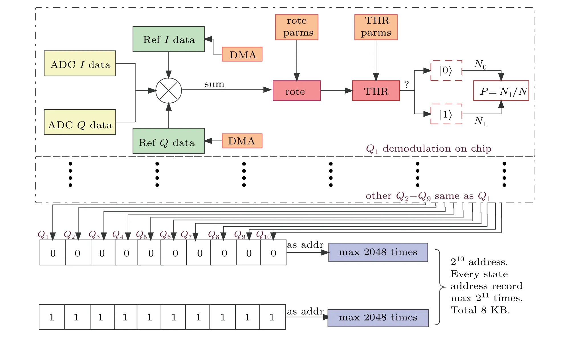
Fig.5. The multi-qubits demodulation logic diagram in FPGA.
4.3. Quantum feedback
Active feedback control of qubits is an essential step to achieve quantum error correction. The low latency is needed in qubit feedback control.[11]Considering low latency,using FPGA as a parallel and fast processing method has more advantages than traditional using central processing unit(CPU).[2,13]
In our system,we may use the readout board for fast feedback. The FPGA on the board controls both the ADCs and AWGs at the same time. Also, we use the real-time parallel demodulation algorithm in FPGA to reduce the calculation time as much as possible. In this demodulation algorithm,demodulation process(Eqs.(4)and(5))and the data acquisition process by ADC are performed simultaneously.
Finally, we determine the total feedback latency related to the hardware by connecting AWGs output to the input of ADCs and measuring the time delay using the following procedure, as shown in Fig. 6. Initially, we let the AWGs generate a simulatedIQsignals that correspond to the|0〉or|1〉state of qubit. After receiving the data,the FPGA will capture the data from ADC and perform data demodulation process to distinguish if the|0〉or|1〉state information is received.Then,the FPGA will trigger AWGs to generate predetermined control pulses accordingly. The time domain corresponding to the feedback latency (plus 5 ns time delay due to 0.5 meter long coaxial cable connecting AWGs and ADCs)is indicated in Fig.6. The obtained feedback latency is about 178.4 ns.
In Table 1, the latency for each step of feedback process is listed. The time on FPGA is determined by its clocks. One clock is 3.2 ns for the FPGA we use. The AWG output time of 4.4 ns is from the chip data sheet. The internal circuit delay is time for AWG signal propagating from AWG chip,through a differential amplifier and filters,to the output SMA connector on the chassis.

Table 1. The parts of feedback logic latency.
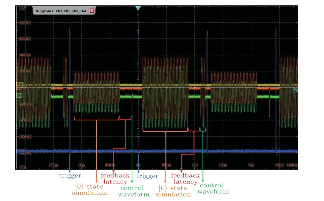
Fig.6. Quantum feedback control test data recorded on an oscilloscope. In this testing,the whole period time is 1.5μs,the readout state simulation time is 819.2 ns, the feedback latency is 178.4 ns and the trigger delay time is 65 ns.
5. Hardware testing
A series of tests have been conducted on our system, including hardware test and application test on qubit devices. A R&S?RTP084 oscilloscopes is used for AWG jitter test and a R&S?FSV3000 signal and spectrum analyzer is used for phase noise and spurious free dynamic range(SFDR)test.
We test the jitter among two AWG channels by simultaneously outputting square signals to the oscilloscope and then recording the delays and standard deviations between these two AWG channels. After testing all six channels on one board,the standard deviations of jitter is about 8 ps.

Fig.7. Phase noise test results of one AWG channel.
The delays of AWG channels are affected by different length of outgoing line. There are three different length types(265 mm,225 mm,and 190 mm). We find that the delays between different AWG channels on the same control board are less than 1 ns and the delays of AWG channels between two different control boards are about 5-6 ns.
In Fig.7,we show the phase noise measured on one AWG channel at seven different frequency values. The noise floor of the equipment is about?140 dBc/Hz. The phase noise with a frequency offset greater than 10 MHz tends to be consistent.Increasing the signal frequency yields downward movement of the phase noise curve.
In the SFDR measurement,the harmonic noise represents the main spurious noise source, especially when the single frequency signal is used. As shown in Fig. 8, SFDR curves with and without harmonic noise are plotted,from 10 MHz to 450 MHz.

Fig.8. Spurious free dynamic range of one AWG channel.
6. Applications of the hardware in multi-qubit characterizations
In order to verify the functionality in qubit control and readout for the hardware system we built, we carried out a number of characterization measurements on a home made 10-qubit device.

Fig.9. The I-Q data for qubit-state differentiation. Blue and red dots are measured I-Q values when qubit is prepared in|0〉and|1〉state,respectively. A total of 5000 dots(repetitions)for each color.
In Fig.9,we show the readout data of 10 qubits. As described in Section 2,these are dispersive readout scheme data with blue and red dots being taken when qubits are in the|0〉and|1〉state,respectively. In this case,the 10 qubits are readout simultaneously.
The energy relaxation timeT1and the dephasing timeT*2results measured of one qubit are displayed in Fig. 10.The control pulses for these measurements are schematically shown in the insets.

Fig.10. (a)T1 and(b)T*2 result of one qubit.
We also performed square wave distortion calibration,with the hardware we built, for square wave signals used for control the energy level spacing. The qubits characterized are energy level tunable ones. In experiments, it is often required to change the energy level quickly by applying a square wave pulse to theZ-control line of one qubit. However, due to the presence of parasitic inductance and capacitance, an ideal square pulse is usually distorted when reaching to the chip, showing overshoot or undershoot near the rising edge and tailed falling edge.
To correct the distortions, we need to determine the deformed square pulse firstly. This is carried out by using the following procedure. The corresponding qubit is biased to a relatively low frequencyfz(more than 1 GH below its maximum frequency) to improve its sensitivity to the pulse shape deformation. An amplitude fixed square pulse is applied to a qubit,and is followed aπpulse with frequencyfz. If there is no distortion, the qubit will be excited to the|1〉state by theπpulse. If there is small distortion after the square wave,the qubit will not be completely excited. By varying the compensation amplitude ?Z,we can find the value of full compensation when the maximum excitation probability is achieved. By changing the delay time ofπpulse, we can get a view of the distorted square wave response. With these response data,we can calculate the needed adjustments for the square pulses.
In Fig. 11, we show the results for one qubit. As illustrated in Fig.11(a),the ideal square pulse(blue)shows distortion(yellow)due to non-ideal response function. After applying the calibrated pulse (green), the response shape reaching the qubit should be close to the ideal one. In Fig. 11(b), the data after the falling edge are shown. As shown in Fig. 8(b),we can measure the falling edge, which should be a straight line with zero voltage under ideal circumstances. The original uncalibrated data and the data after calibrations are shown.We repeat the pulse correction process three times,indicating as the first,second,and third-order calibration in the figure.

Fig.11. (a)The Z pulse correction schematics and(b)correction results after the falling edge.
Finally, we characterize single qubit gate fidelity using random benchmarking.[15]In this kind of measurement,a random sequence of gates belonging to the single qubit Clifford group is prepared and the experimental fidelity is obtained.This is set as the reference test. Then,to measure the fidelity of a specific gate,the gate is interleaved with m random Cliffords and perform the same measurement. By comparing with the reference, the average fidelitys of the gates are obtained.In Fig. 12, the representative reference gate sequence corresponding to 10 random Cliffords (separated by the dashed lines), and a recovery gate (in light blue region) are shown schematically. The measurement results displayed in Fig. 13 are for six gates of single qubit. For each gate, the operation time is 50 ns. The results show that averaged gate fidelity is better than 99.68%for the six gate we characterize.

Fig.12. Representative reference gate sequency.

Fig.13. Random bench marking result.
7. Conclusion
We have designed, built and tested a hardware system used for the control and readout of superconducting multiqubit devices. The system consists of multi-channel AWG boards, DC bias board, and readout boards. The AWG has 2.5 GHz sample rate and 16-bit voltage resolution. The system can be used for more and more energy level tunable qubit readout and control by connecting more and more boards and chassis. Efforts have been made to reduce the system latency and the total feedback latency related to the hardware is about 178.4 ns. The system has been used to characterize a 10-qubit device,demonstrating its usability in practical quantum experiments.
猜你喜歡
Chinese Physics B(2022年4期)2022-04-12 03:44:38
Chinese Physics B(2021年12期)2021-12-22 06:43:42
Chinese Physics B(2021年10期)2021-10-28 07:03:24
汽車維修技師(2019年7期)2020-01-16 04:32:54
中學生英語·外語教學與研究(2019年9期)2019-12-02 07:27:48
伙伴(2019年9期)2019-10-21 11:30:18
Chinese Physics B(2019年8期)2019-08-16 01:19:16
Chinese Physics B(2017年9期)2017-08-30 08:25:38
飛言情B(2017年3期)2017-03-28 21:22:09
小雪花·成長指南(2015年6期)2015-08-13 17:29:19
- Chinese Physics B的其它文章
- Erratum to“Floquet bands and photon-induced topological edge states of graphene nanoribbons”
- Viewing the noise propagation mechanism in a unidirectional transition cascade from the perspective of stability*
- Nonlinear signal transduction network with multistate*
- Optical strong coupling in hybrid metal-graphene metamaterial for terahertz sensing*
- Any-polar resistive switching behavior in Ti-intercalated Pt/Ti/HfO2/Ti/Pt device*
- Magnetic two-dimensional van der Waals materials for spintronic devices*