
Numerical simulation of cementing displacement interface stability of extended reach wells *
2018-07-06 10:01:42JintangWang王金堂BaojiangSun孫寶江HaoLi李昊ZhiyuanWang王志遠(yuǎn)
水動(dòng)力學(xué)研究與進(jìn)展 B輯 2018年3期
Jin-tang Wang (王金堂), Bao-jiang Sun , (孫寶江), Hao Li , (李昊), Zhi-yuan Wang , (王志遠(yuǎn)),
Yong-hai Gao 1, 2(高永海)
1. School of Petroleum Engineering, China University of Petroleum (East China), Qingdao 266580, China
2. National Engineering Laboratory for Testing and Detection Technology of Subsea Equipments, Qingdao 266580, China
Introduction
The development of the drilling and completion technologies of extended reach wells helps to efficiently explore the oilfields of low permeability, low abundance and thin reservoir, and the shallow sea oilfields[1-4]. The horizontal displacement of an extended reach well is twice more than that of the vertical depth or is above 3000 m[5-6]. Technical problems facing the cementing displacement of an extended reach well are as follows[7-10]. First, the horizontal section of an extended reach well is too long, making the drilling fluid displacement difficult.Second, the gravity makes the casing eccentric, thus affecting the displacement efficiency of the cementing and the interface stability. Third, the friction accumulation compresses the casing string and thus makes it buckle, resulting in a complex annulus channel structure between the borehole and the casing as well as making it difficult calculating the velocity and the interface distribution. During the cementing, an unstable cementing interface is the main factor for generating the partial displacement of the drilling fluid by the cement slurry[11]. Because of the annular flow channel and the effect of gravity, the interface between the cement slurry and the drilling fluid during the displacement is gradually transformed from the steady state, the unstable state to the extreme of the drilling-fluid channeling. The displacement interface instability mixes the dilution section with the cement slurry and the drilling fluid, affecting the performance of the cement slurry and thus weakening the strength of the cement with increased permeability. When the displacement interface becomes very unstable, in the annulus, a continuous fluid channeling is formed,resulting in the zonal isolation failure.
Along with the numerical simulation of the displacement of the annulus cement slurry, many experiments and numerical calculations were conducted, mainly on the casing eccentricity in a vertical section as well as the effects of the rheological property of the cement slurry and the pad fluid on the cementing displacement efficiency. An increase of the return velocity, a decrease of the viscosity of the cement slurry, the improvement of the borehole regularity and the casing centering degree as well as the application of the turbulence displacement would significantly improve its displacement efficiency[12-13].Numerical calculation of the annulus flow behavior of a non-Newtonian fluid using the finite element method was conducted[14]. The velocity distribution in the displacement interface and the annulus crosssection of a cement slurry in a horizontal well section by building a 3-D annulus borehole was obtained[15].Malekmohammadi[16]studied the displacement of a vertical eccentric annulus plug flow, assuming that even though with a large eccentricity, with appropriate two-phase viscosity ratio, density ratio, and velocity,the interface can be stabilized.
In this study, a fluid dynamics software and the VOF method[17]are used to track and reconstitute the interface. The annulus cementing displacement of the cement slurry under a complex borehole condition is numerically simulated. Moreover, the influences of complex borehole conditions, such as the deviation angles, the eccentricity, and the casing centralizer, on the cementing displacement interface stability of extended reach wells are studied. The optimization studies improve the displacement efficiency, thus providing a theoretical tool for designing the cementing of extended reach wells.
1. Geometric model of annulus flow channel
Using the completion data of the Shengli Oilfield Z129 extended reach well, a three-dimensional space model with an annulus flow channel of 10 m long,0.2159 m in outer diameter, and 0.1397 m in inner diameter is built. The annulus flow channel can be adjusted by varying the deviation angle, the dimensionless eccentricity, and by using different types of casing centralizers in the calculation.
2. Mathematical models and discretization
2.1 Assumptions
(1) The drilling fluid is the Herschel–Bulkley fluid and the flow is the incompressible viscous flow.
(2) The mass transfer, the boundary layer effect of the wall and the heat transfer of the wall are neglected, to simplify the computation.
(3) The roughness of the casing and the borehole is assumed to be constant.
2.2 Basic governing equations
For the annulus borehole, the flow-governing equations, including the continuity equation and the momentum equation, are established. For we have to deal with a turbulent flow when the fluid enters the pump, the -kε model (ANSYS FLUENT User’s Guide, Section 12.6) for the turbulence calculation is used.
Continuity equation

Momentum equation

Energy conservation equation

Turbulent kinetic energy equation
Turbulent kinetic energy dissipation rate equation
For the two-phase flow

where ρ is the fluid density,i,jare the indices to locate the cells (inx,yorzdirection),tis the time,uis the velocity,pis the pressure,hkis the heat-transferring coefficient,pcis the specific heat capacity of the fluid,Tis the temperature, μ is the dynamic viscosity,TSis the viscosity dissipation term,kGis the turbulent kinetic energy generated by the mean velocity gradient,bGis the turbulent kinetic energy generated by the buoyancy,YMis the effect of the compressive turbulence pulsation expansion on the total dissipation, μtis the turbulence viscosity coefficient, μt= ρ/ε, α1,α2are the mass fractions of the two phases.
2.3 Auxiliary equations and boundary conditions
The auxiliary equations include the equation for the eccentricity model, the flow equations, and the equations for the average velocity, the critical Reynolds number, and the critical velocity[18].
(1) Eccentricity model
Under ideal conditions, the center of the casings should be consistent with that of the borehole.However, in practical engineering, it is not the case.Therefore, the dimensionless eccentricity ε is defined as the departure degree between the casing and borehole centers. A mathematical equation for the dimensionless eccentricity ε can be expressed as the ratio of the casing eccentric distance (OO′) to the concentric annular clearance (R-r).

The eccentric annulus flow section can be considered as a flow channel of unequal height ()h.The inner and outer radii areRandr. Assuming thatO′is the casing center andOis the borehole center, ε′ is the eccentric distance ( )OO′. A polar coordinate (,)rα is built with the center of the casing center as the origin as shown in Fig. 1. The annulus cross-section is symmetrical about the line connecting the two circles’ centers ( )OO′. In Fig. 1,αvaries in the range of 0°-180° andhis the function of α.
According to the geometric relationship, the equation ofhcan be expressed as follows


Fig. 1 Eccentric annulus structure diagram
IfRε′
? , thenhcan be simplified as follows

where ε′ is the eccentric distance,Ris the annulus outer radius,ris the annulus inner radius.
When =0α, we have the maximum annular clearance, when =1α, we have the minimum annular clearance. With a larger eccentricity, the wide gap in the annulus would become wider, and the narrow gap would be narrower. When the eccentricity is 0, the annulus is concentric. When the eccentricity is 1, the casing contacts with the wall.
(2) Flow equations

(3) The average velocity equation in the annulus flow of the H-B fluid is obtained as follows:

(4) The Reynolds number of the H-B fluid is derived as follows:

The displacement mechanism shows that the turbulent flow is in the best displacement flow pattern,whereas the plug and laminar flows are in poorer displacement flow patterns. If the cement slurry has a large viscosity, the flow is difficult to become turbulent. Because the cementing pump cannot have the required displacement rate and pump pressure, it takes a longer cementing time to form the plug flow.Sometimes, we will not have the plug flow at all in view of the restriction of the thickening time of the cement slurry. Fowler (1947), Lindgren (1958), Leite(1959), and Wygnanski and Champagne (1973)suggested that the Reynolds number is in the range of 1800<Re< 2300 when the flow is in transit from the laminar flow regime to the transition regime.
(5) Displacement efficiency
The displacement efficiency (η) is defined as:

where η is the displacement efficiency,caVis the volume of the cement slurry in the annulus after displacing to the end,olVis the volume of the annulus,Lis the length of the cementing section.
When =1η, the drilling fluid is completely displaced by the cement slurry. When <1η, the drilling fluid is partially displaced by the cement slurry. The lower the value of η, the worse the cementing quality becomes.
Boundary conditions: The boundary condition of the velocity inlet is used for the entrance, and the velocity inlet is set according to different displacements. The outlet pressure boundary condition is used.No slip condition is applied for the solid boundary,where =0uon the solid wall. The wall roughness of the borehole is 7.62 mm, whereas the wall roughness of the casing is 0.15 mm.
2.4 Mathematical model discretization
The numerical discrete method is used to solve the problem generated by the finite volume method with double precision, and a structured grid is used to generate the space grid, where the convective term is treated with the first-order upwind scheme, and the velocity–pressure term is solved by using the SIMPLE method. Based on the results of a large number of cement slurry rheology experiments, the rheological constitutive equation of the cement slurry is proposed.Using a user-defined-function procedure, the constitutive parameters of the fluid are fed into the software solver to accurately describe the flow characteristics of the cement slurry and the displacement interface.
To complete these governing equations, the auxiliary equations for the cementing annulus flow are established. By solving these equations, the fluid pressure field, the velocity field, and the mass flux are obtained. In view of the fact that we have a turbulent flow when the fluid enters the pump in a project, thek-εmodel for the turbulence calculation is used.
3. Analyses of simulation results
3.1 Effect of deviation angle on the cementing displacement interface stability of extended reach well
The extended reach well has a complex structure,a long horizontal section, and a wide variation of deviation. The rheological properties of the well cementing slurry systems are listed in Table 1. In the computational domain, the simulated displacement fluid is a cement slurry with a density of 1 900 kg/m3and a dynamic viscosity of 90 mPa·s. The fluid displaced is a drilling fluid with a density of 1 100 kg/m3and a dynamic viscosity of 20 mPa·s. The experimental studies suggest that the Herschel–Bulkley model can be used as the rheological model of the cement slurry with a yield pressure of 18 Pa. The consistency coefficientKand the liquidity indexnare 0.64 Pa·snand 0.756, respectively. Moreover, the yield pressure of the drilling fluid is 5 Pa, whereas the consistency coefficientKand the liquidity indexnare 0.43 Pa·snand 0.633, respectively.
According to the on-site investigation, the annulus displacement velocity is between 0.1 m/s and 2.0 m/s. To maintain the turbulence displacement, the displacement velocity in the simulation is set as 1.5 m/s.Then, the deviation angle varies from 0° to 90° to determine the effect of the hole deviation angles on the cementing displacement interface stability of the extended reach well. Figure 2 shows the distribution of the displacement interface when the deviation angle is 90° and its variation with time. In this figure, the red zone represents the cement slurry (1), whereas the blue one represents the drilling fluid (0). For the simulation, the flow direction is along theXaxis, and the gravity is along the negativeZaxis direction.
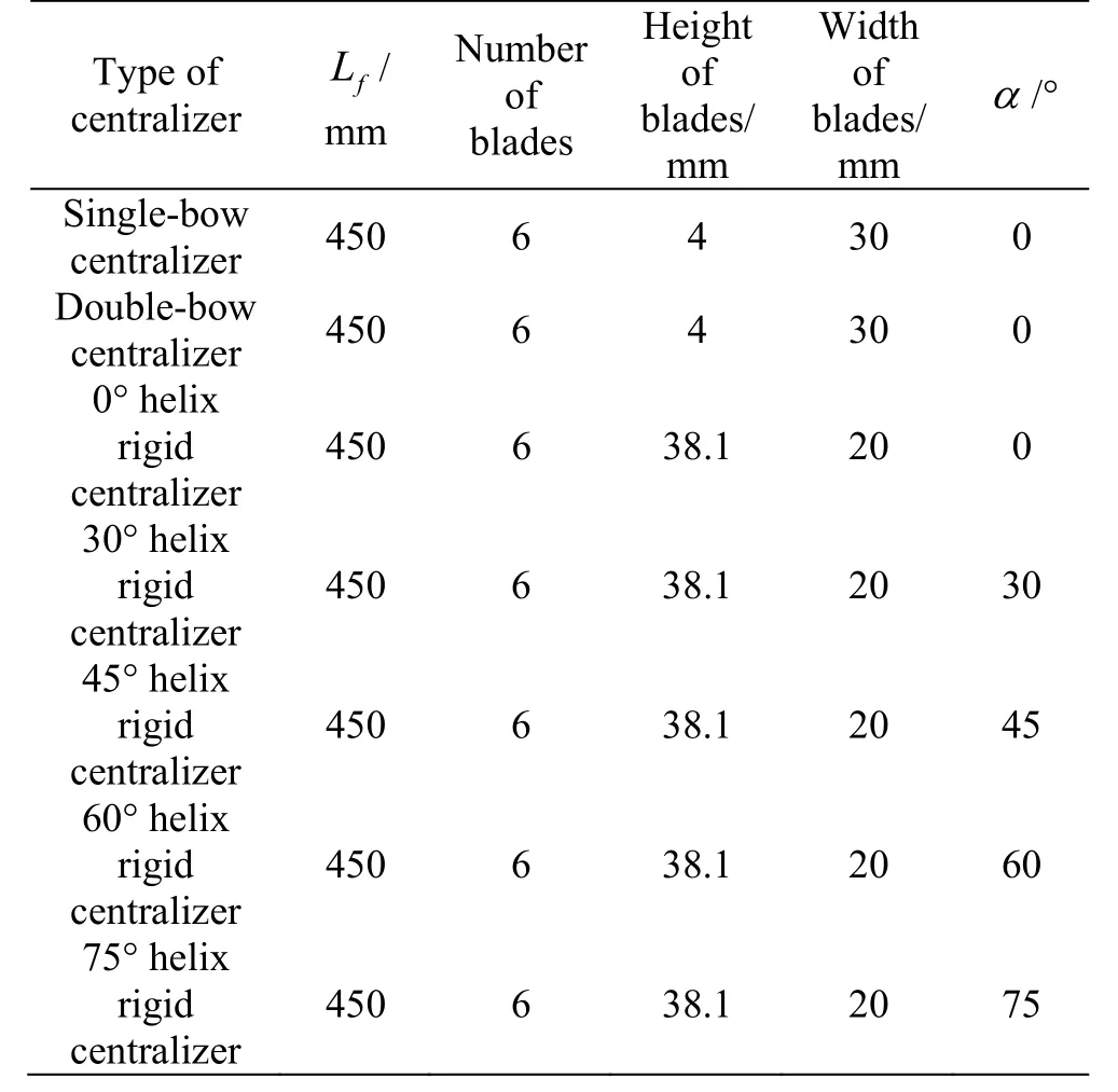
Table 1 Different casing centralizer structures

Fig. 2 (Color online) Distribution of displacement interface and its variation with time when the deviation angle is 90°

Fig. 3 Variations of length displacement interface with time for different deviation angles
Cfis the cement slurry volume fraction, as shown in Fig. 2. Because of gravity, the cement slurry is distributed in the lower part of the borehole annulus and moves forward in the first place as its density is larger than that of the drilling fluid, thus increasing the displacement interface to some degree. Moreover,with the progress of time, the interface mixing region becomes longer. In the Fig. 3DTis the displacement time,MRLis the mixing region length. It shows the variation of the length of the displacement interface with the displacement time when the deviation angles are 0°, 30°, 60° and 90°.
The simulation results indicate that with the same displacement time, the length of the displacement interface increases with the increase of the deviation angle. Moreover, with the progress of time, the length of the displacement interface mixing section has an approximately linear relationship with the displacement time. Because of the related properties of the cement slurry, the drilling fluid, and their gravity, at different points of the fluid in the annulus are acted by different loads. This uneven stress distribution and the effect of gravity hinder the uniform movement of the cement slurry. Specifically, the cement slurry moves more on the low stress side of the displacement interface and less on the high stress side. Moreover,the larger the deviation angle, the higher the effect of gravity on the displacement interface, and the lower the entire annulus displacement efficiency. The instability of the annulus displacement interface can change the property of the cement slurry, resulting in drilling fluid channeling. The simulation results show that the lengths of the critical mixing section corresponding to the deviation angles of 0°, 30°, 60°and 90° are 6.02 m, 5.24 m, 4.58 m and 4 m, respectively. When the practical length of the interface mixing section exceeds the critical value, the local drilling fluid will be retained. This is also observed from the displacement efficiency graph for different deviation angles as shown in Fig. 4.

Fig. 4 Displacement efficiency graphs for different deviation angles
ADis the deviation angle,EDis the displacement efficiency, Fig. 4 shows that with the increase of the deviation angle, the displacement efficiency decreases gradually. Particularly when the deviation angel is larger than 60°, the displacement efficiency is decreased dramatically, from 96.32% to 94.51%.Moreover, with the increase of the displacement time,the effect of the deviation angle on the cementing displacement becomes clearer. Under the same displacement conditions, the displacement efficiency of both the highly deviated well and the horizontal well is lower than that of the vertical well.
Thus, in the cementing displacement progress in the horizontal section of the extended reach well, it is necessary to decrease the density difference between the cement slurry and the drilling fluid. This indicates that a cementing technology with a low density difference can be used to decrease the effect of gravity on the interface instability. Moreover, under the turbulence displacement condition, to maintain stability of the displacement interface and improve the cementing displacement efficiency, the displacement velocity of the cement slurry should increase to guarantee the turbulence.
3.2 Effect of eccentricity on the cementing displacement interface stability of extended reach well
The eccentricity of the underground casing string is inevitable, which will affect the sectional annulus channel and thus affect the velocity distribution of the cement slurry in the annulus. The distributions of the cementing displacement interface against the eccentricities are obtained by setting the dimensionless eccentricity as 0.1, 0.2, 0.3, 0.4, 0.5, 0.6, 0.7 and 0.8.Figure 5 shows the variations of the displacement interface with time when the eccentricity is 0.7.

Fig.5 (Color online) Distribution of the displacement interfaces with time when the eccentricity is 0.7
As shown in Fig. 5, the eccentricity of 0.7 significantly affects the cementing displacement interface. With the progress of time, the coning occurs on the displacement interface, and the inclination of the interface is clear. Because of the combined effects of the eccentric annulus gap and the gravity, the cement slurry makes a sudden move during the annulus flow.The cement slurry flows under the drilling fluid, and one sees a stratified flow, causing a severe instability of the displacement interfaces, which is bad for the cementing displacement of the cement slurry. In the vertical borehole, as the gravity only works in the axial direction, the velocity distribution on the sectional gap is uneven.

Fig. 6 Velocity distributions along the radial direction in theannulus for different eccentricities
Vcis the cement slurry velocity, Fig. 6 shows the velocity distribution along the radial direction in the annulus for different eccentricities. Because of the effects of the eccentricity, the velocities in wide and narrow gaps show uneven distributions. The velocity in the wide gap is larger than that in the narrow gap.With the increase of the eccentricity, this tendency becomes more severe. When the eccentricity is 0.8,the ratio of the maximum velocities in the wide and narrow gaps is 6.3, i.e., the cement slurry in the wide gaps moves forward faster than that in the narrow gaps.
For the horizontal borehole, Fig. 7 shows the variation of the lengths of the displacement interface with time for different eccentricities.

Fig. 7 Variation of lengths of displacement interface with time for different eccentricities
The interface instability caused by the eccentricity is due to the uneven velocity distribution in the axial and radial directions. Because of the eccentricity,the resistance in wide and narrow gaps is different from each other, leading to a difference in the axial velocity. A larger eccentricity results in a clearer velocity difference, a longer displacement interface length, a less stable interface, and a lower displacement efficiency, as indicated theoretically and experimentally[14-15]. A decrease of the casing eccentricity is an effective method to maintain the displacement interface stability and improve the displacement efficiency.

Fig. 8 Lengthsof critical mixing regionswheninstability occurs under different eccentricity conditions
ε is the eccentricity,CMRLis the critical mixing region length, as shown in Fig. 8, the length of the critical mixing region during the instable process decreases rapidly with the increase of the eccentricity.During the operation of an extended reach well, the casing eccentricity cannot be avoided, leading to a complex annulus channel structure in the borehole, an uneven velocity distribution on the annulus section, an easier drilling fluid retention in the annulus borehole,and more frequent cement channeling.

Fig. 9 Effect of casing eccentricity on displacement efficiency for different deviation angles
Figure 9 shows the effect of the casing eccentricity on the displacement efficiency for different deviation angles. It is shown that with the change in the deviation angle from 0° to 30°, 60° and 90°, the displacement efficiency decreases as the eccentricity increases. Particularly, when the eccentricity is above 0.5, the displacement efficiency decreases dramatically. When the deviation angle is larger than 90°, this trend becomes mild. Specifically, in the horizontal section of the extended reach well, the displacement interface stabilityis maintained in the annulus when the casing is eccentric to some extent, slightly affecting the displacement efficiency.
In this study, the variations of the displacement interface length with time for different eccentricities and cementing displacement efficiencies are compared by using the numerical simulation. It is concluded that the eccentricity should be controlled under 0.5 to maintain a high displacement efficiency for the cementing quality. For the control of the casing eccentricity, the first step should be to guarantee a good drilling quality to decrease the deviation angle to the greatest extent. Moreover, a whirl casing centralizer should be used because it not only improves the casing centering degree, but also changes the flow of the annulus fluid from a straight flow into a rotational flow, decreasing the channeling of the cement slurry.
3.3 Effects of different types of casing centralizers onthe cementing displacement interface stability of extended reach wells
3.3.1Introduction of casing centralizers and their sizes
The casing centralizers used on-site are generally single-bow centralizers, double-bow centralizers, and rigid centralizers. The use of a casing centralizer can help to center the casing, reduce the eccentricity, and improve the displacement efficiency. According to the on-site situation, three types of centralizers are used in the modeling in this study. Moreover, based on the angle between the holding up bands and the axial direction, rigid centralizers are divided into 0°, 30°,45° and 60° helix angle rigid centralizers. The structure of a rigid centralizer is shown in Fig. 10.

Fig. 10 Structure of a helix rigid centralizer
In Fig. 10,fLis the length of the centralizer blade, αis the angle between the blades and the axis of the casing centralizer,fiDandfoDare the diameters of the vertical projection of the internal and external trace lines of the centralizer blades, respectively. Their specific parameters are shown in Table 1.
3.3.2 Experimental validation
To validate the simulation accuracy of the addition of the blades of the helix swirl centralizer, the results are compared with the existing experimental data from the literature[19].
In the experiment, the test section is 6.096 m long, 0.1778 m in outer diameter, and 0.127 m in inner diameter of the annulus structure. A helix swirl centralizer is used for the tests. The blade height is 0.022 m, and the blade length is 0.095 m. The blade angle for the helix swirl centralizer is fixed at 45°. The rheological properties of the fluid follow a power law,where the values ofKand n are 8.6 Pa·snand 0.35,respectively. Two sets of 18 flow-angle measuring devices are located along the two sides of the test-cell axis, 180° apart (inside A and B).
Simulations are carried out under the same experimental conditions including the annulus structure,the helix swirl centralizer size, and the fluid rheology.The effective swirl length (Ls) and the swirl angle(Sa) are introduced to investigate the effect of the centralizer. The effective swirl length is the axial distance along the casing annulus, where the flow angle is > 3° inclined with the axis direction[17]. The swirl angle is the flow angle, i.e., the deviation in the angle of the flow direction from the axis.
A comparison of the simulated and experimental values of the effective swirl length and the swirl angle is shown in Fig. 11,SDis the swirl degree.

Fig. 11 Swirl angle distribution and comparison between simulated and experimental data in literature
To validate the accuracy of the simulation more intuitively, the deviation of the calculated data from the experimental data in literature is calculated by

whereSacalis the calculated value of the swirl angle,Sadocis the experimental data in literature of the swirl angle, and ΔSais the average absolute deviation.
The deviations between the simulated data calculated by a software and obtained by experiments are small, the average absolute deviation is <3.76%analyses.3.3.3Cementing displacement interface distribution of extended reach wells for different types of casing centralizers
The casing centralizers used on-site are generally single-bow centralizers, double-bow centralizers, and rigid centralizers. The use of a casing centralizer can help to center the casing, reduce the eccentricity, and improve the displacement efficiency. According to the on-site situation, three types of centralizers are used in the modeling in this study. Moreover, according to the angle between the holding up bands and the axial direction, the rigid centralizers are classified into 0°,30°, 45°, 60° and 75° helix angle rigid centralizers. In view of the characteristics of the extended reach wells,the deviation angle in the model is 90°. The effects of different types of casing centralizers on the cementing displacement interface stability of the extended reach wells are evaluated. Figure 12 shows how an annulus displacement interface is developed with time by using a helix angle rigid centralizer of 60°.
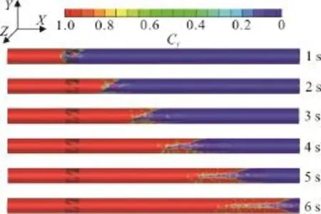
Fig. 12 (Color online) Diagram of how an annulus displacement interface is developed with time by using a helix angle rigid centralizer of 60°
As shown in Fig. 12, the addition of a whirl rigid centralizer into the borehole annulus significantly improves the interface stability and shortens the length of the mixing section. With the increase of the displacement time, the cementing displacement interface shows no instability. The interface between the cement slurry and the drilling fluid is clear, and the interface inclining angle is small, as is beneficial for the cementing displacement of the cement slurry.

Fig. 13 Variation of the length of displacement interface against displacement time when different types of casing centralizers are used
Figure 13 shows the variations of the displacement interface length against the displacement time when different types of casing centralizers are used.The calculation results show that single-bow and double-bow centralizers are good for centralization,but the displacement interface stability is only slightly improved. When the deviation angle is sufficiently large, the casing gravity makes the centralizer fail due to its limited strength; therefore, the centralizer bows show no significant effect on the casing improvement.Therefore, in the horizontal section of the extended reach wells, the whirl centralizers should be used instead of the single-bow and double-bow centralizers for their better rigidity. Because the helical bow changes the structure of the annulus channeling, the tangential velocity of the fluid is generated, with a good washing effect on the virtual filter cake in the borehole as well as with a nice displacement effect.From the velocity distribution on the section at the centralizer exit position, it is shown that the maximum velocity could reach 2.48 m/s, intensifying the turbulence of the cement slurry displacement. Thus, the whirl centralizers can help the removal of the fluid and improve the displacement efficiency of the cementing.
3.3.4Recommendation for the best helix angle of a
rigid centralizer
During the injection of the cement slurry in the well cementing, restricted and guided by the centralizer holding up bands when the fluid flows through a whirl centralizer, the cement slurry is confined, and its trace is changed, to generate a helical flow velocity field. The field construction shows that a tripping in the whirl centralizers has no harmful effect on the normal cementing construction. After the tripping in the centralizer, the effective whirl section can change the flow type of the cement slurry and improve the displacement interface stability. Moreover, different helix angles have different whirl effects on the cement slurry. According to the simulation results of 0°, 30°,45°, 60° and 75° helix centralizers, by comparing their flow fields, the best helix angle of a rigid centralizer is recommended.
The cement slurry flowing in the annulus of a helix swirl centralizer has three distinct phases: the phase before flowing to the inlet of the annulus of the helix swirl centralizer, the phase when flowing in the internal region of the annulus of the helix swirl centralizer, and the phase when flowing out of the annulus of the helix swirl centralizer.sAis the swirl angle. As shown in Fig. 14, in the phase before the cement slurry flows to the inlet of the annulus of a helix swirl centralizer, the flow behavior appears to be a single axial flow. When the fluid flows in the internal region of the annulus of a helix swirl centralizer, a swirling flow is developed. After flowing out of the annulus of the helix swirl centralizer, the flow becomes an axial swirl flow, and the tangential velocity decreases gradually. With the increase of α (the angle between the centralizer blades and the casing centralizer axis), the swirl angel increases, but with a decreasing rate. The maximum swirl angels of 0°, 30°, 45°, 60° and 75° helix rigid centralizers are 0°, 16.72°, 28.33°, 36.12° and 41.21°,respectively.
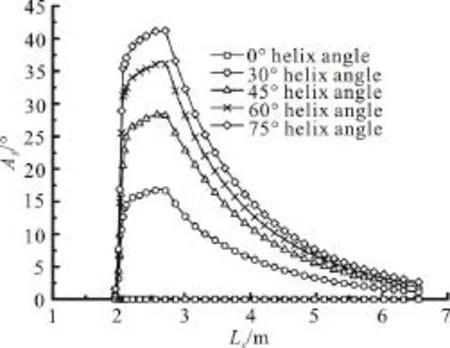
Fig. 14 Swirl angel distributions along the axial direction in the annulus of a helix swirl centralizer with different helix angles
In Fig. 15, (Rφ-Rin) denotes the distance from a certain point in the annulus to the outer wall of the casing. (Rout-Rin) is the width of the annular clearance. The ratio of (Rφ-Rin) to (Rout-Rin) is taken as the abscissa and represents the non-dimensional distance of a certain point in the annulus relative to the annulus width. The value of the non-dimensional distance changes in the range of –1 to 1 as the point location moves from the casing outer wall to the wellbore.

Fig. 15 Tangential velocity distributions along the radial direction in the annulus of a helix swirl centralizer with different helix angles
VTis the tangential velocity, as shown in Fig. 15,the tangential velocity at the center in the radial direction in the annulus of a helix swirl centralizer is larger than that close to the wall. When the helix angle is 45°, the tangential velocity increases significantly as compared to the case with 30° helix angle. Because of the tangential velocity, the flow field of the displacement annulus is changed. An increase of the helix angle of a rigid centralizer in a wellbore can alter the fluid flow field during the displacement and increase the circumferential effect of the whirl and the reflux, ensuring a better stability of the displacement interface and improving the displacement efficiency.Because a helix swirl centralizer stays in the annulus,the path of a cement slurry makes a helical flow. To measure the intensity of an annulus fluid vortex, a nondimensional swirl number is introduced. The swirl number can be expressed as follows[20]

whereZUis the axial velocity,tUis the tangential velocity,outRis the outer annular radius,inRis the inner annular radius,Rφis the distance from a certain micro element to the axis in the annulus.
The swirl number indicates the relative strength of the tangential and axial movements of the fluid in the wellbore annulus. The larger the swirl number, the higher the swirl intensity, and the better the displacement effects, particularly near the borehole wall.SNis the swirl number,HCAis the centralizer helix angle. As shown in Fig. 16, because of the changes of the annular structure, the cement slurry generates a tangential velocity. The swirl number increases with the increase of the tangential velocity.

Fig. 16 Swirl number distributions in the wellbore annulus with different helix angles
Figure 17 shows the displacement efficiency curves obtained when the centralizers with different helix angles are used. As the helix angle of the holding up bands increases from 0° to 75°, both the whirl length and the cementing displacement efficiency increase as well. When the helix angle is increased from 30° to 45°, the whirl length is increased more rapidly. However, when the helix angle is above 45°, the increasing helix angle of the holding up bands slightly improves the cementing displacement efficiency, thus remaining stable.

Fig. 17 Displacement efficiencies using centralizers with different helix angles
Overally, the casing whirl centralizers show some positive effects on the improvement of the cementing displacement efficiency. Based on the displacement efficiency and the friction in the annulus at the oilfield cementing site, the whirl centralizers with 45° helix angle are suggested for centering the casing.
3.4 Methods for improving the cementing displacement interface stability of extended reach wells
During the operation of the extended reach wells,the casing eccentricity often occurs. A potential casing eccentricity or buckling deformation still occurs after the casing centralizer is added. This paper, based on the basic drilling data obtained in Z129, combined with the field practical situation and complex borehole conditions, studies the rheological behavior and the displacement velocity of the cement slurry for the cementing for improving the displacement interface stability and efficiency during the operation of extended reach wells in different spuds in sections using numerical simulations.
(1) Numerical simulation of cementing displacement in the first spudding
The annulus structure of the first spudding is of the dimention of 444.5 mm×339.7 mm, with the deviation angle ranging from 15° to 25°, as in a high centering degree. A single-bow casing centralizer is used to ensure the eccentricity to fall between 0 and 0.2. By changing the yield value, the density, the viscosity, and the displacement velocity of the cement slurry, the displacement interface stability and efficiency of the first spudding are evaluated.
The numerical simulation results indicate that the effect of the borehole annulus velocity on the displacement interface stability during the first spudding is relatively slight, particularly when the interface of the drilling fluid sees almost no instability. This is because the effect of the density difference uniformly moves the displacement fluid forward and thoroughly displaces the drilling fluid. The density difference between the cement slurry and the drilling fluid in the first spudding section should be above 500 kg/m3,whereas the viscosity difference between them is controlled between 50 mPa·s and 60 mPa·s. The optimal yield pressure of the cement slurry is 10 Pa.VDis the displacement velocity. Figure 18 shows that when the velocity in the first spudding section reaches 0.9 m/s, exceeding the critical turbulent flow velocity,the displacement efficiency satisfies the requirements.However, the effect of a further increase of the velocity on improving the displacement efficiency is not clear.

Fig. 18 Annulus displacement efficiencies of every spudding with different flow velocities
(2) Numerical simulation of cementing displacement in the second spudding
The annulus structure of the second spudding section is of the dimension of 311.2 mm×244.5 mm,with its deviation angle ranging from 25° to 60°. A combination of elastic and rigid centralizers is used to ensure the eccentricity to fall between 0 and 0.4. By changing the yield value, the density, the viscosity,and the displacement velocity of the cement slurry, the displacement interface stability and efficiency of the second spudding are evaluated.
The numerical simulation indicates that the cement slurry interface suffers from a severe instability with the deviation angle in some range; therefore,the deviation angle significantly affects the displacement efficiency. In the place where the deviation angle changes dramatically, the fluid shows an uneven velocity distribution in the annulus flow channel,resulting in different turbulent degrees inside and outside. This inhibits the cement slurry displacement and decreases the cementing displacement efficiency.To maintain the interface stability, the density difference between the cement slurry and the drilling fluid in the second spudding section should be controlled between 400 kg/m3-500 kg/m3, whereas the viscosity difference between them is controlled between 50 mPa·s and 60 mPa·s. The optimal yield pressure of the cement slurry is between 12 Pa and 15 Pa.Figure 18 shows that the displacement velocity dramatically affects the displacement efficiency.When the flow velocity is below 0.8 m/s, the cement slurry is in a laminar state and is significantly affected by the deviation angle. Because of the effect of the density difference, a clear stratification is observed on the interface, and the overall displacement efficiency cannot be guaranteed. When the flow velocity is further increased to above 1.2 m/s, the cement slurry is in a complete turbulence flow state in the annulus,as is more beneficial for the cementing displacement.Moreover, with a practical pump delivery and formation bearing ability, under the premise of a turbulent displacement, a proper increase of the displacement can guarantee a good displacement efficiency. This study shows that the borehole annulus displacement of the second spudding section can achieve the best performance when the flow velocity is 1.2 m/s.
(3) Numerical simulation of cementing displacement in the third spudding
The annulus structure of the third spudding section is of the dimension of 215.9 mm×139.7 mm,with its deviation angle ranging from 60° to 91.86°.The combination of elastic and rigid centralizers is used to ensure that the eccentricity falls between 0 and 0.8, but in some casing one likely sees a buckling deformation. By changing the yield pressure, the density, the viscosity, and the displacement velocity of the cement slurry, the displacement interface stability and efficiency of the third spudding are evaluated.
According to the numerical simulation results,with the increase of the deviation angle, along with the effect of the eccentricity, the displacement interface becomes more uneven, and the interface segregation becomes clearer. At this time, more 45° helix centralizers should be installed and the density difference between the cement slurry and the drilling fluid in the third spudding section should be controlled under 200 kg/m3, whereas the viscosity difference is between 60 mPa·s-70 mPa·s. The optimal yield pressure of the cement slurry is 18 Pa. Fig. 18 shows that the optimal flow velocity of the borehole annulus displacement in the third spudding is 1.1 m/s.When the flow velocity is less than this value, the displacement efficiency is increased with the increase of the flow velocity. However, when the flow velocity exceeds 1.1 m/s, the displacement efficiency is only slightly affected.
4. Conclusions
According to the numerical calculations for different well deviation angles and eccentricities, different types of casing centralizers, the influencing factors on the cementing displacement interface stability of the extended reach wells with a complex borehole annulus are revealed as follows:
(1) With the same displacement time, the displacement interface length increases as the deviation angle increases. With the increase of the displacement time, the length of the displacement interface mixing section is approximately linearly related to the displacement time.
(2) When the eccentricity is larger, the velocity difference will be clearer, and the length of the displacement interface will be longer, with a more unstable interface and a poorer displacement efficiency.When the value of the eccentricity is 0.8, the ratio of the maximum velocities in the wide and narrow gaps is 6.3. To guarantee a higher displacement efficiency of the cementing quality, the eccentricity should be controlled under 0.5.
(3) The use of casing centralizers can dramatically improve the interface stability and decrease the mixing section length of the interface, which is beneficial for the cementing displacement of the cement slurry. The results are compared with the existing experimental data. The deviations between the simulation data calculated using the software and the experimental data are small, and the average absolute deviation is <3.76%. The swirl number increases with the increase of the tangential velocity.A comparison shows that the 45° helix angle of the rigid centralizers is recommended for field applications.
[1] Vishal A., Gupta V., Shashank N. et al. Extended-reach open-hole gravel pack completion under multiple complexities [C].SPE Bergen One Day Seminar, Bergen,Norway, 2017.
[2] Zhu X., Yi J., Liu Q. Distribution features of cuttings bed and sensitivity analysis of major drilling parameters for cuttings transport in gas drilling horizontal wells [J].Journal of Hydrodynamics, 2015, 27(6): 884-893.
[3] Dutra E. S., Martins A. L., Miranda C. R. Dynamics of fluid substitution while drilling and completing long horizontal-section wells [C].SPE Latin American and Caribbean Petroleum Engineering Conference, Rio de Janeiro, Brazil, 2005.
[4] Wang J., Sun B., Li H. et al. Simulation analysis of rotating-casing cementing displacement in extended reach well [J].Journal of China University of Petroleum(Edition of Natural Science), 2015, 39(3): 89-97.
[5] Wang R., Li M., Wang C. et al. Research progress in the cementing displacement mechanism [J].Natural Gas Industry, 2013, 33(5): 69-76.
[6] Foroushan H. K., Ozbayoglu E., Gomes P. J. et al. Mudcement displacement in eccentric annuli: analytical solution, Iinstability analysis, and computational fluid dynamics simulations [C].IADC/SPE Drilling Conference and Exhibition, Texas, USA, 2018.
[7] Muhammad Z., Mayank T. Development of simulations based correlations to predict the cement volume fraction in annular geometries after fluid displacements during primary cementing [J].Journal of Petroleum Science and Engineering, 2016, 145(9): 1-10.
[8] Alexandre L. Effect of eccentric annulus, washouts and breakouts on well cementing quality: laminar regime [J].Energy Procedia, 2016, 86(2): 391-400.
[9] Chen P., Gao D., Wang Z. et al. Study on aggressively working casing string in extended-reach well [J].Journal of Petroleum Science and Engineering, 2017, 157(8):604-616.
[10] Ozbayoglu E. M., Foroushan H. K., Miska S. Z. et al. On the instability of the cement/fluid interface and fluid mixing [J].SPE Drilling and Completion, 2018, 33(1):63-76.
[11] Pelipenko S., Frigaard I. A. Mud removal and cement placement during primary of an oil well Part 2; steadystate displacements [J].Journal of Engineering Mathematics, 2004, 48(1): 1-26.
[12] Bu Y., Tian L., Li Z. et al. Effect of casing rotation on displacement efficiency of cement slurry in highly deviated wells [J].Journal of Natural Gas Science and Engineering, 2018, 52(4): 317-324.
[13] Tardy P. M. J., Bittleston S. H. A model for annular displacements of wellbore completion fluids involving casing movement [J].Journal of Petroleum Science and Engineering, 2015, 126(2): 105-123.
[14] Ozbayoglu E. M., Omurlu C. Analysis of the effect of eccentricity on the flow characteristics of annular flow of non-newtonian fluids using finite element method [C].SPE/ICoTA Coiled Tubing Conference and Exhibition,Texas, USA, 2006.
[15] Mark S., Robert D., Wilson C. Modeling fluid interfaces during cementing using a 3D mud displacement simulator[C].Offshore Technology Conference, Texas, USA, 2007.
[16] Malekmohammadia S., Carrasco T. M., Storey S. An experimental study of laminar displacement flows in narrow vertical eccentric annuli [J].Journal of Fluid Mechanics, 2010, 649: 371-398.
[17]Hardt S., Wondra F. Evaporation model for interfacial flows based on a continuum-field representation of the source terms [J].Journal of Computational Physics, 2008,227(11): 5871-5895.
[18] Ermila M., Eustes A., Mokhtari M. Using magnetorheological fluids to improve mud displacement efficiency in eccentric annuli [C].SPE Eastern Regional Meeting,Kentucky, USA, 2012.
[19] Therond E., Taoutaou S., James S. G. et al. Understanding lost circulation while cementing: field study and laboratory research [J].SPE Drilling Engineering, 2018, 33(1):77-86.
[20] Parisa S., Alessandro S., Jens K. Experimental investigation of the stability limits of premixed syngas-air fl ames at two moderate swirl numbers [J].Combustion and Flame,2016, 164(2): 270-282.
猜你喜歡
中國火炬(2023年4期)2023-04-21 01:45:38
Chinese Physics B(2022年11期)2022-11-21 09:27:42
民間文學(xué)(2022年1期)2022-03-31 23:47:35
四川勞動(dòng)保障(2021年9期)2022-01-18 05:11:04
電影文學(xué)(2021年17期)2021-10-14 08:56:50
Chinese Physics B(2019年6期)2019-06-18 05:42:14
民間文學(xué)(2018年3期)2018-04-28 08:07:28
食藥用菌(2016年3期)2016-04-05 20:57:10
小學(xué)生作文·小學(xué)低年級(jí)適用(2016年1期)2016-03-07 08:22:24
中國畜牧獸醫(yī)文摘(2015年9期)2015-12-29 03:38:08
 水動(dòng)力學(xué)研究與進(jìn)展 B輯2018年3期
- 水動(dòng)力學(xué)研究與進(jìn)展 B輯的其它文章
- Numerical simulation of wave-current interaction using the SPH method *
- The influence of perforated plates on wave transmission and hydrodynamic performance of pontoon floating breakwater *
- URANS simulations of the tip-leakage cavitating flow with verification and validation procedures *
- Pressure characteristics of hydrodynamic cavitation reactor due to the combination of Venturi tubes with multi-orifice plates *
- Transport feasibility of proppant by supercritical carbon dioxide fracturing in reservoir fractures *
- Effect of blade shape on hydraulic performance and vortex structure of vortex pumps *