
Application of response surface methodology for optimization of purge gas recycling to an industrial reactor for conversion of CO2 to methanol
2017-05-28 10:23:16HadisehKhalilpourmeymandiAzadehMirvakiliMohammadRezaRahimpourAlirezaShariati
Hadiseh Khalilpourmeymandi,Azadeh Mirvakili,Mohammad Reza Rahimpour ,*,Alireza Shariati
1 Department of Chemical Engineering,School of Chemical and Petroleum Engineering,Shiraz University,Shiraz 71345,Iran
2 Department of Chemical Engineering,School of Chemical and Petroleum Engineering,Persian Gulf University,Bushehr 75169,Iran
3 Shiraz University,Natural Gas Engineering Department,School of Chemical and Petroleum Engineering,Shiraz 71345,Iran
1.Introduction
Environmental issues due to emissions of gases induced by petrochemical industries have become worldwide problems.The proportion of gases has increased significantly.Millions of cubic meters of gases are burnt and wasted annually in fuel oil installations in all around the globe[1].This is the beginning of entering millions of tons of carbon dioxide into the atmosphere and therefore the environment is affected by this action.Furthermore,negative changes in climate can highly increase through production of carbon dioxide,black carbon,and the other environmental contaminants.Moreover,there are valuable gases in such flares which are wasted.As a result,they should be utilized in order to lead to a sustainable economic prosperity in developing countries.
Iran is the third largest country in the world which produces flare gases.The requirement of collecting purge gases and optimum applying of such detrimental gases are quite perceptible due to environmental and economic problems caused by burning and wasting them.In fact,they can be recycled to the unit to pollution reduction and its efficient use.
The aim of this study is to recycle the purge gas of methanol unit.In order to realize more comprehensive description of methanol production process and modeling,a few mathematical modeling studies on this process are provided.
There are a vast variety of research projects about the modeling of methanol unit[2–5].In 2004,Rahimpour and Ghader[6]investigated the enhancement of carbon monoxide conversion in a membrane named palladium–silver membrane for methanol synthesis.A novel reactor con figuration with perm-selective Pd–Ag(23 wt%Ag)wall to hydrogen was proposed in their studies.Furthermore,a wide range of important operation conditions were examined.The simulation results demonstrated that carbon monoxide conversion beyond equilibrium value can be enhanced by a membrane reactor.A dynamic model for a membrane dual-type methanol reactor in the presence of long term catalyst deactivation was developed by Rahimpour and Lotfinejad[7]in 2007.The performance of a membrane dual-type methanol reactor in comparison with the conventional one was investigated.Indeed,a favorable temperature pro file and the activity of membrane dual-type reactor relative to single and conventional dual-type reactor systems were shown by simulation results.Accordingly,when a membrane was used in a conventional dual-type methanol reactor,the performance of methanol reactor systems improved.The potential for methanol production from natural gas by direct catalytic partial oxidation was also examined by Edwards and Foster[8]in 1986.
Purge gas streams of methanol unit contain approximately 63%hydrogen,20%carbon monoxide and carbon dioxide as reactants and 17%nitrogen and methane as inert.For the purpose of recycling the components of purge gas streams,optimal recycle components have been determined by RSM.
1.1.Response Surface Methodology(RSM)
The relationships between numerous explanatory variables and one or more response variables are explored by RSM which had been presented by Box and Wilson[9]in 1951.RSM is employed to optimize the recycle components.
Up to now,different studies have been accomplished on optimization of various processes by RSM[10–14].Samimiet al.[15]has attempted to improve conditions of an industrial methylacetylenepropadiene(MAPD)hydrogenation reactor during the hydrogenation operation with the investigation and modification of different parameters which can directly affect the performance of reactor.The effect of different parameters on the rate of propylene production has been investigated by using RSM.A continuous production of biodiesel from waste cooking oil in a reactive distillation column catalyzed by solid hetero poly acid was done by Noshadiet al.[16]in 2012.RSM based on central composite design(CCD)was utilized to design the experiment and analyzed parameters such as reboiler duty,total feed flow rate,feed temperature and methanol/oil ratio.
A combination of computational fluid dynamics(CFD)and RSM were utilized by Kumar and Bansal[17]in 2013 in order to model and optimize the photo catalytic degradation of Rhodamine B in an annular photo catalytic reactor.After modeling and simulating the photo catalytic process with CFD,the RSM was utilized for optimization of the process based upon data derived from the CFD simulations.It was indicated that CFD and RSM could be applied for the optimization of photo catalytic processes in order to save time,cost and effort.The catalytic pyrolysis of waste high-density polyethylene to liquid fuel over modified catalysts was optimizedviaRSM by Kumar and Singh[18]in 2014.Countless parameters such as reaction temperature,acidity of modified catalysts and mass ratio between modified catalysts and waste highdensity polyethylene(HDPE)were selected as independent variables.The obtained quadratic model fitted well to predict the response with a high determination coefficient ofR2(0.995).The optimization process with reduced number of costly experiments was successfully achieved by RSM.According to the results which were obtained by RSM,membrane was applied in order to separate gas components.
1.2.Membrane
Membrane separation technology is a low-cost process when high purity gas streams are not fundamental[19].Membrane processes for gas separation are gaining a larger acceptance in industries and markets.Adsorption ofCO2,CH4,N2O,and N2on MOF-5,MOF-177,and zeolite 5A was investigated by Sahaetal.[20]in 2010.Both adsorption equilibrium and kinetic data for these gases on all three adsorbents were volumetrically measured at 298 K and gas pressure up to 800 Torr.They understood that both MOF adsorbents have larger adsorption capacities for CO2and CH4in comparison to zeolite 5A at elevated pressure.The influences of gas pressure on diffusivity for various adsorbate–adsorbent systems were also investigated by these authors.Besides,Mfi membranes for carbon dioxide separation were prepared and th
e separation performance was evaluated by Lindmark and Hedlund[21]in 2010.The permeance of CO2for this membrane was as high as 13 × 10?7mol·m?2·s?1·Pa?1.Their simulation results clearly showed that Mfi membranes were promising candidates for separating carbon dioxide from synthesis gas.Furthermore,Salehiet al.[22]studied the enhancement of carbon monoxide conversion in a novel slurry bubble column reactor for methanol synthesis in 2014.They compared the results of carbon monoxide removal with gas-phase model in the quasi-steady state condition.They finally achieved higher methanol production rate and lower catalyst deactivation rate.Carbon nanotubes(CNTs)with several amines were modified by Suet al.[23]in 2009.These amines included 3-aminopropyl-trimethoxysilyl(APTS),ethylenediamine(EDA)and polyethyleneimine(PEI).The modified CNTs were tested at temperature ranging from 20 to100°C in order to absorb carbon dioxide.The highest capacity of carbon dioxide adsorption was achieved by CNT-APTS at the lowest applied temperature;i.e.55 mg·g?1of CNT-APTS in comparison with 37 mg·g?1of raw CNT.
1.3.Objective
There are two purge gas streams in the methanol production unit of domestic petrochemical company that its total flow rate is 1,293,000 mol·h?1.Each purge gas stream contains 63%hydrogen and 20%carbon monoxide and carbon dioxide which are the valuable and beneficial reactants for methanol production reaction.Besides,there is 17%nitrogen and methane as inert gases in the methanol purge gas streams.
Consequently,the main goal of the current study is to investigate the recycling effect of different components on the methanol production rate.It is undoubted that recycling all components of purge gas leads to production reduction owing to inert gas accumulation.Therefore,the inert gases should be separated from the purge gages and only reactants are recycled to the reactor.A membrane gas separation unit has been considered as a purification unit for separating methane and nitrogen from the purge gas streams.In addition,maximizing methanol production rate and minimizing carbon dioxide production rate have been taken into consideration in this paper.With these purposes in mind,the optimization method of RSM is applied.The optimal value of different parameters like temperature,inlet flow rates of carbon dioxide,carbon monoxide and hydrogen are calculated by RSM.
2.Process Description
A schematic diagram of methanol synthesis unit is shown in Fig.1(a).The methanol synthesis unit contains shell and tube heat exchanger which the first reactor(water-cooled reactor)is combined serially with the second one(gas-cooled reactor).Cold feed synthesis gas is preheated inside the tubes of the second reactor(gas-cooled reactor),and subsequently fed into the tube side of the water-cooled reactor where the chemical reaction is initiated by catalysts.Reactions of methanol synthesis are performed over commercial CuO/ZnO/Al2O3catalyst.In this stage,synthesis gas is partly converted into hydrocarbons.The reacting gas leaving the water-cooled reactor is directed into the shell side of the gas-cooled reactor in counter-current mode with synthesis gas flowing through the tube side.The next stage is the purification of the produced methanol.The outlet of reactors is cooled until that methanol is condensed.Purge gases and methanol condensation are separated in a flash drum.The output of the drum unit is divided into two parts:
?95%of unconverted syngas is recycled back to the methanol converter to enhance the overall conversion,thereby improving the process economically.
?The residual unconverted syngas(approximately 5%)is used as purge gas.
As clearly observed in Fig.1(b),four branches of purge gas streams are available:
1-The first stream is zero flaring which means absolute no flaring;closed flare.
2-The second stream is sent to feed pretreatment as a hydrogen rich stream and mixed with methane gas for feed desulfurization.The flow rate of this stream is 8157 m3·h?1.
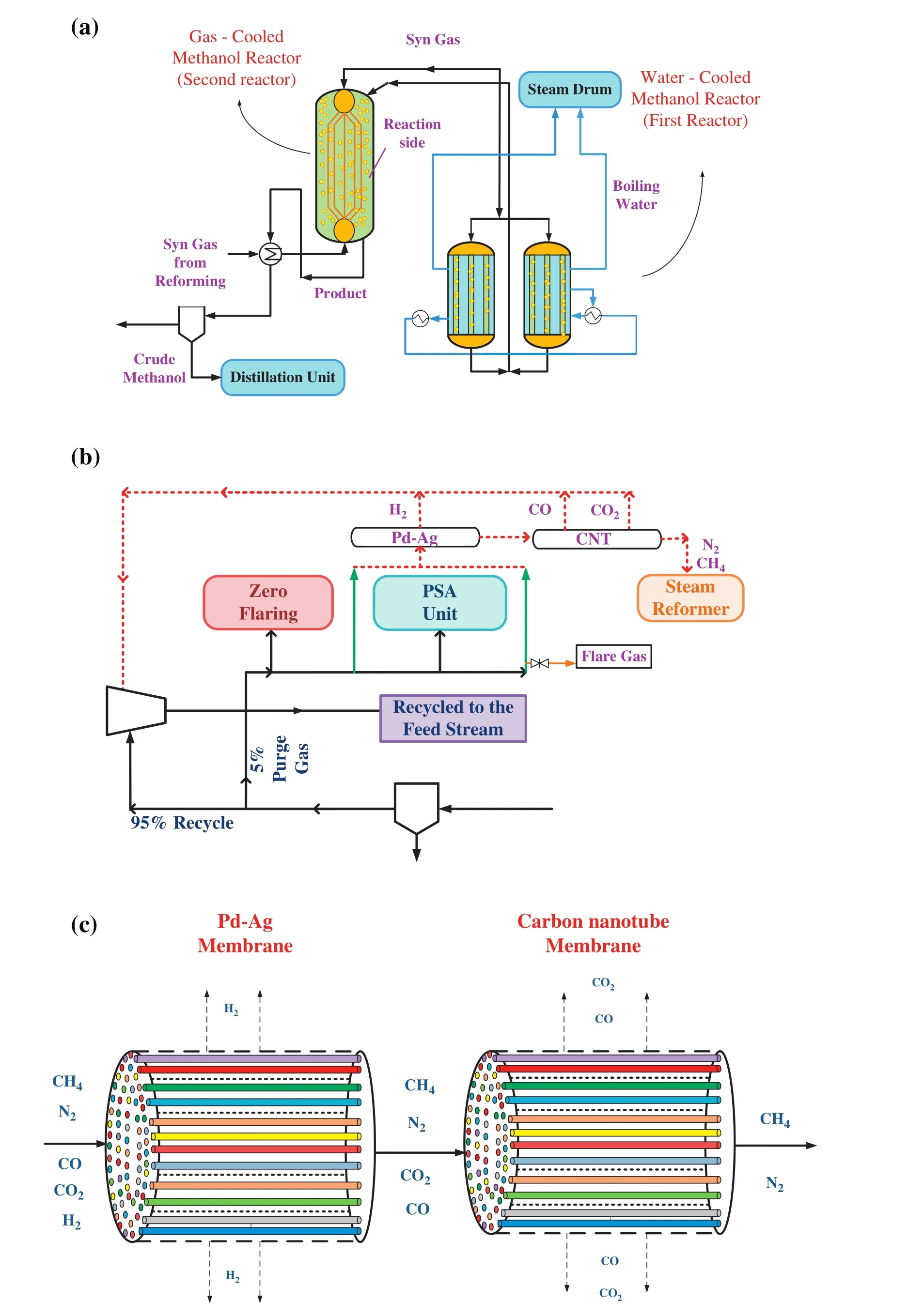
Fig.1.Schematic diagram of(a)a methanol production unit,(b)methanol purge gas streams and(c)purge gas purification unit.
3-The third stream is sent to the hydrogen recovery by the process of pressure swing adsorption(PSA)which cannot be returned to the reactor.
4-The fourth steam is sent to the steam reformer and it is used as fuel in the steam reforming unit.The flow rate of this stream is 22,679 m3·h?1.
There are two returnable purge gas streams in the domestic petrochemical company.One of them is utilized as fuel;however,the other purge gas stream is used as hydrogen rich stream in the desulfurization unit.Although COand CO2are considered as inert gases in the desulfurization unit,they are reactants of methanol synthesis reactors.Therefore,it is suggested that this branch of purge gas stream is recycled to the feed stream.Another stream is used as fuel in the steam reformer.Fuel is much cheaper than purge gas because actually purge gas is an unreacted synthesis gas which is considerably pricey to be produced.As a matter of fact,by recycling all components not only nitrogen and methane as inert gases are accumulated in the reactor during recycling,but also it reduces the reaction rate;moreover,methanol production rate decreases.Therefore,it is necessary to apply a purification unit before recycling these two purge streams in order to remove unwanted components such as nitrogen and methane.
For the purpose of gas separation,various methods can be introduced which are cryogenic method,absorption with lean oil,adsorption and membrane processes.Membrane processes have been utilized as a purification unit for separating gas components in the current study owing to their simplicity and low maintenance costs.
2.1.Purification unit
Hydrogen is the smallest component in the methanol purge gas stream.There is approximately 63%hydrogen in the purge gas.As a result,at first a membrane should be designed for hydrogen separation.There are many membranes for separating hydrogen in the literature.Pd-Ag,a popular membrane for H2separation,is examined in this study.Afterwards,CO and CO2should be separated from the gas mixture;therefore,carbon nanotubes(CNTs)are proffered.
17%of methanol purge gas contains inert gases like nitrogen and methane.Because of separating such inert gases,a Pd–Ag membrane is applied for hydrogen removal;furthermore,carbon nanotubes(CNTs)are preferred in order to separate carbon dioxide and carbon monoxide.A schematic diagram of this purification unit is illustrated in Fig.1(c).
Consequently,hydrogen,carbon dioxide and carbon monoxide are recycled to the feed of methanol unit in order to increase the methanol production rate.Besides,methane can be used as fuel in the methanol production unit and nitrogen can be converted into NOxin the steam reforming unit.
3.Reaction Scheme and Kinetics
Methanol synthesis includes three overall reactions.They are as follows:
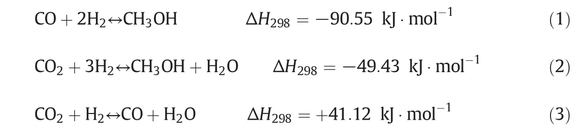
Reactions(1)–(3)are not independent so that one is a linear combination of the other ones.In the current work,the rate expressions have been selected from Graafet al.[24].The rate equations combining with the equilibrium rate constants provide enough information about kinetics of methanol synthesis[3].The corresponding rate expressions due to the hydrogenation of CO,CO2and reversed water–gas shift reactions over commercial CuO/ZnO/Al2O3catalysts are:
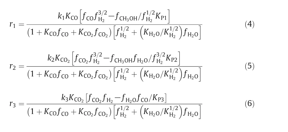
The reaction rate constants,adsorption equilibrium constants and reaction equilibrium constants in the formulation of kinetic expressions have been tabulated in Table 1,respectively.
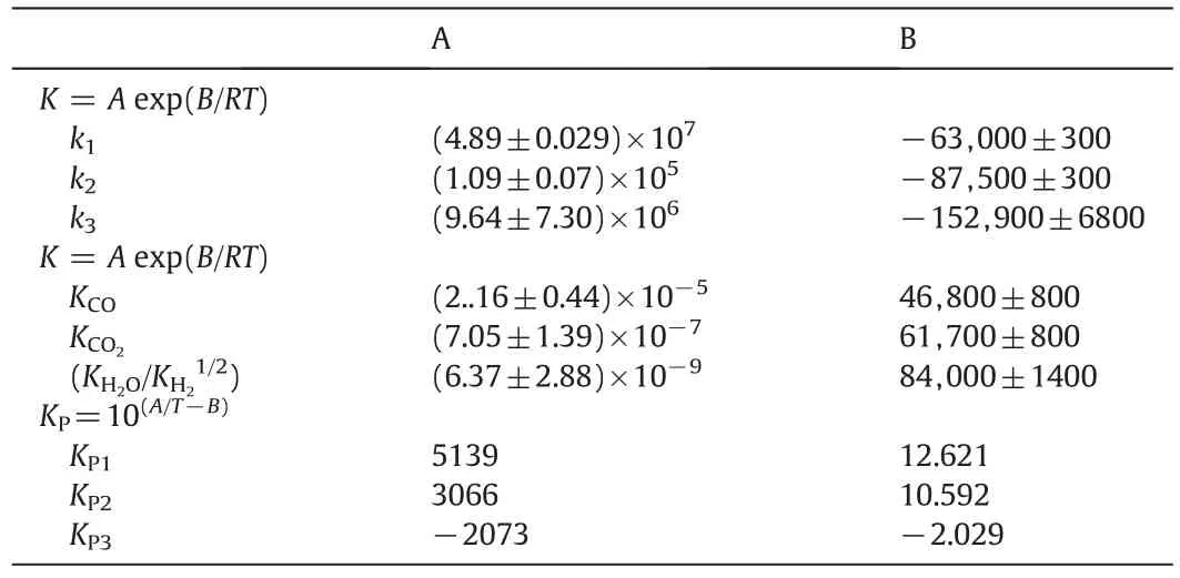
Table 1The reaction rate constants,the adsorption equilibrium constants,and the reaction equilibrium constants for methanol synthesis
4.Mathematical Model
4.1.Fixed bed reactors
A one-dimensional heterogeneous model,which is a conventional model for a catalytic reactor with heat and mass transfer resistances,has been developed for this reactor in order to determine concentration and temperature distributions inside the reactor.The reactor is simulated by MATLAB software.In this model the following assumptions are used:
The gas mixture is an ideal gas in both catalytic reactors[6,7].
Both reactors are operated at steady-state conditions.
Radial variations in both beds are negligible(one-dimensional model).
Axial diffusion of mass and heat are negligible.
Bed porosity in axial and radial directions is constant.
A one-dimensional plug flow in shell and tube sides is considered.
Chemical reactions are assumed to take place only in the catalyst particles.
Heat loss to surrounding is neglected.
4.1.1.Solid phase
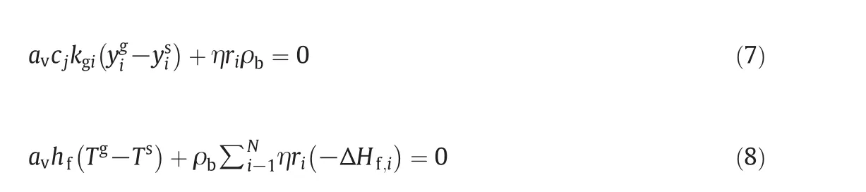
The mass and energy balances for the solid phase are obtained as follows:whereyssandTsare the solid-phase mole fraction and temperature for components(6 components)iin the reactor and η is the effectiveness factor.
4.1.2.Fluid phase
The following mass and energy balance equations are developed for the fluid phase:
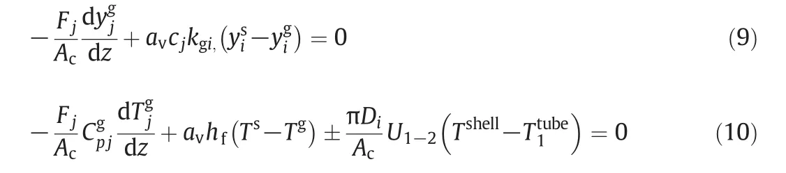
whereyigandTgare fluid phase mole fraction and temperature for componentiin the reactor,respectively.The energy equation consists of heat transfer by convection and exchanged heat between the fluid phase and solid phase.Boundary conditions are as follows:

whereyi0,gT0gandP0gare fluid phase mole fraction,inlet temperature of the reactor,and pressure at the entrance of the reactor,respectively.
4.2.Puri fi cation unit
The flux of hydrogen permeating through Pd–Ag membrane is as follows:
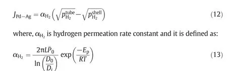
pH2demonstrates the hydrogen partial pressure in Pa.The outer and inner diameters of the Pd/Ag layer are presented by D0and Diin turn.The pre-exponential factorP0above 200°C is reported as 6.33 × 10?8mol·m?2·s?1·Pa?0.5and the activation energy,Ep,is 15.7 kJ·mol?1[25].
Furthermore,the permeating flux through CNT membrane has been shown in Eq.14.
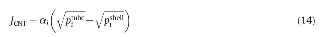
where,α is 0.16 barrel for carbon dioxide permeation and the permeation rate constant for carbon monoxide has been assumed approximately near the permeation rate constant of carbon dioxide.
5.Model Validation
The formulated model composed of11 ordinary differential equations and the associated boundary conditions lends itself to be an initial value problem.The algebraic equations in the model incorporate the initial conditions,the reaction rates,the ideal gas assumption,as well as aforementioned correlations for the heat and mass transfer coefficients and the physical properties of fluids.These equations along with the discretized ordinary differential equations using backward finite difference form a set of non-linear algebraic equations.The reactor length is then divided into 100 separate sections and the Gauss–Newton method in MATLAB programming environment is used to solve the non-linear algebraic equations in each section.Following this,the results are obtained and validated.The steady state model validation is performed between the pilot plant data reported by domestic petrochemical company and the mathematical modeling of CRC.Results of CRC model and the corresponding observed data of the pilot plant are presented in Table 2.A good agreement is observed between the modeling results and the pilot plant data.Therefore,this mathematical model performs well under industrial conditions.
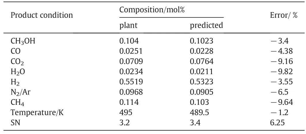
Table 2Comparison of mole percent between model results with plant data for fresh catalysts in CRC
6.Results
The aim of this study is to recycle purge streams into the methanol production reactor in order that the methanol production increases.According to the investigations,recycling all components from purge streams is not appropriate and effective.At first,the in fluence of recycling different gases from purge streams to the feed of methanol production unit has been studied.
1.recycling CO,CO2,H2,CH4and N2from purge streams;
2.recycling just CO,CO2and H2from purge streams;
3.recycling just CO and H2from purge streams;
4.recycling just CO and CO2from purge streams;
5.recycling just CO2and H2from purge streams;
6.recycling just CO from purge streams;
7.recycling just CO2from purge streams;
8.and recycling just H2from purge streams.
Despite recycling just H2and COis the bestcon figuration,there is almost no membrane to separate CO2from CO.Therefore,an appropriate purification unit has been performed in order that CO2,H2and CO are separated from the other components in the purge streams which is named as Desired Recycle Con figuration(DRC).The gas separation method is described in the process description section.In this study,the modeling results of DRC and CRC have been compared with each other.
Fig.2 illustrates methanol flow rate according to different recycling con figurations.As shown,the maximum methanol flow rate is achieved in the third con figuration which is related to recycling just COand H2to the feed stream.As described before,however it is the best con figuration,due to limitation in separation technology,recycling of the mixture of CO,CO2and H2is investigated and it is named as DRC.
Methanol production rate increases by approximately 0.106%in the second con figuration compared to CRC.As mentioned before,the second con figuration describes returning CO,CO2and H2from two purge gas streams to the methanol feed stream named as DRC.
Fig.3 shows methanol flow rate as a function of reactor length.As obviously, firstly methanol flow rate rises sharply during the first reactor length and then it increases smoothly during the second reactor length which is owing to high reaction rate in the beginning of reaction.It is clearly seen that the flow rate of methanol increases when DRC is applied.In other words,when DRC is applied,the flow rate of methanol is approximately increased by 0.106%in comparison with the one in CRC.Methanol flow rate enhancement demonstrates not only the superiority of DRC to CRC,but also the increase in profit obtained from DRC.
Hydrogen is one of the main reactants for methanol production.A comparison of hydrogen flow rate in DRC and CRC has been proposed in Fig.4.Generally hydrogen flow rate decreases along the reactor length owing to its fast consumption during the reactions.The flow rate of hydrogen increases considerably in DRC in comparison with the one in CRC.It is due to this fact that there is about 63%hydrogen in each purge stream which is recycled to the reactor feed stream.Obviously,the flow rate of hydrogen in DRC increases by nearly 0.39%compared to the one in CRC.A further advantage of applying DRC is the reduction of catalyst cocking caused by increasing hydrogen flow rate.
Molar flow rate of methanol,carbon dioxide,carbon monoxide,water and hydrogen at the end of the reactor is depicted in Fig.5(a)–(c)for CRC and DRC.As clearly seen,the proportion of produced methanol in DRC is higher than the one in CRC.
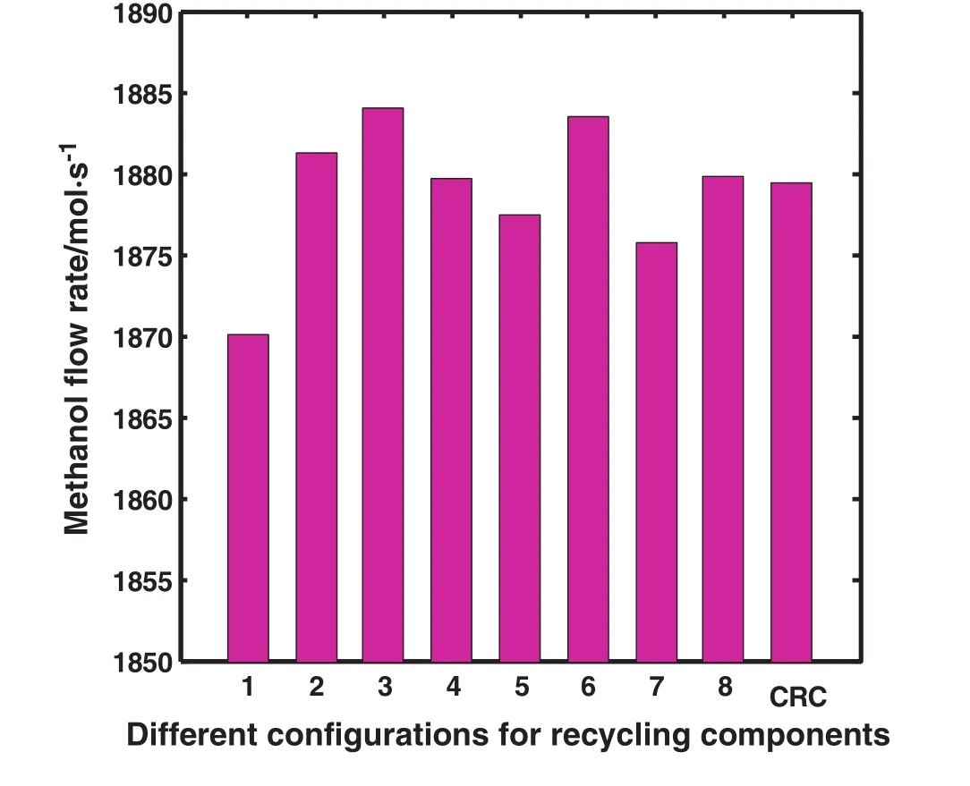
Fig.2.Schematic diagram of different con figurations comparing methanol flow rate in the outlet.
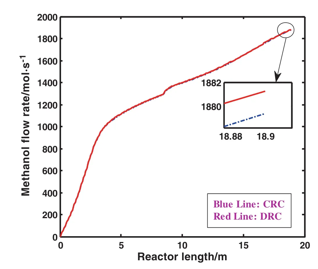
Fig.3.Comparison of methanol flow rate as a function of reactor length in CRC and DRC.
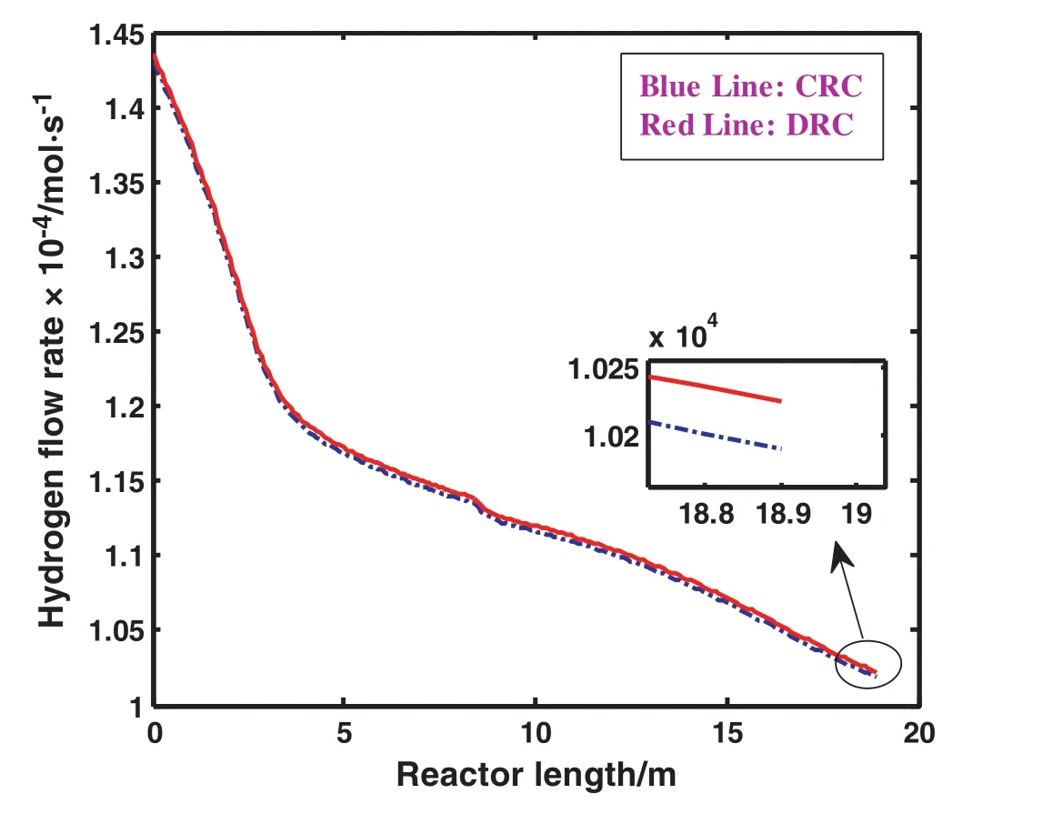
Fig.4.Comparison of hydrogen flow rate as a function of reactor length in CRC and DRC
The percentage of different component's conversion such as hydrogen,carbon dioxide and carbon monoxide versus the reactor length for both CRC and DRC are demonstrated in Fig.6(a)–(c),respectively.In Fig.6(a),hydrogen conversion increases dramatically in the first two meters of the reactor and afterward it rises gradually.It can be seen from Fig.6(b)that there is a dramatic rise in the conversion of CO2along the reactor length to approximately 12.5%in the first four meters of the reactor.Subsequently,having leveled off until the second 4 m of the reactor,CO2conversion then increases gradually.Moreover,it is obvious from Fig.6(c)that reactor the conversion of CO in the first grows sharply in comparison to the second reactor.Generally,the percentage of these component's conversions has risen in DRC compared to the one in CRC.It occurs because the consumption of hydrogen,carbon dioxide and carbon monoxide in DRC is higher than the one in CRC.
By applying DRC,the effect of recycling purge streams to the reactor on temperature along the reactor length is negligible.
The money obtained from methanol sale for DRC and CRC is depicted in Fig.7.The difference between the money which has been obtained from methanol sale in DRC and CRC is approximately 3763.649$·day?1.As clearly shown,the money obtained from methanol sale in DRD is about1.001 times more than the one in CRC.As a matter of fact,obtaining more money from methanol sale in DRC is one of the advantages of applying this novel con figuration which is profitable.
Fig.8(a)and(b)gives information about the effect of recycling hydrogen and carbon monoxide to the reactor on the methanol production along the reactor length,respectively.It is depicted that as recycling hydrogen and carbon monoxide to the reactor increases,the methanol production enhances as well.Moreover,these figures show that hydrogen and carbon monoxide are the beneficial components which are highly effective in increasing the methanol production.
The influence of recycling hydrogen on the rate of carbon dioxide production along the reactor length is illustrated in Fig.9.As recycling hydrogen from purge streams to the feed of reactor increases,the flow rate of carbon dioxide reduces.This is the superiority of recycling much more proportion of hydrogen from purge streams to the reactor feed stream.
7.Optimization
In the simplest case,an optimization problem consists of maximizing or minimizing a real function by systematically choosing input values from within an allowed set and computing the value of the function.The generalization of optimization theory and techniques to other formulations comprises a large area of applied mathematics.It is imperative to optimize the industrial operations,manufacturing and engineering activities in order to be more efficient.A mathematical model,which predicts the process behavior,is required to optimize the chemical and related processes[26].
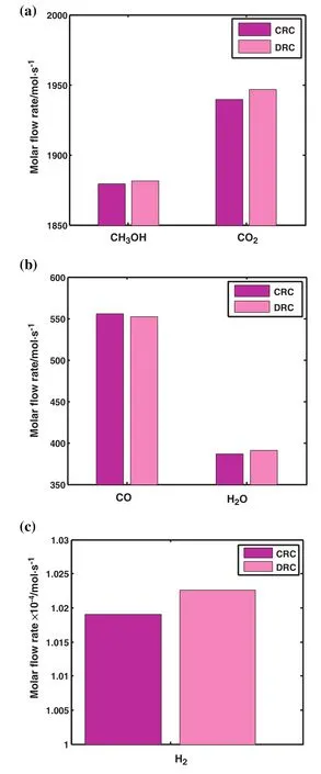
Fig.5.Comparison of molar flow rate of(a)CH3OH and CO2,(b)CO and H2O(c)H2 in the outlet of CRC and DRC.
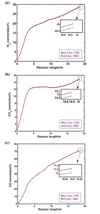
Fig.6.Comparison of(a)hydrogen,(b)carbon dioxide and(c)carbon monoxide conversion in CRC and DRC.
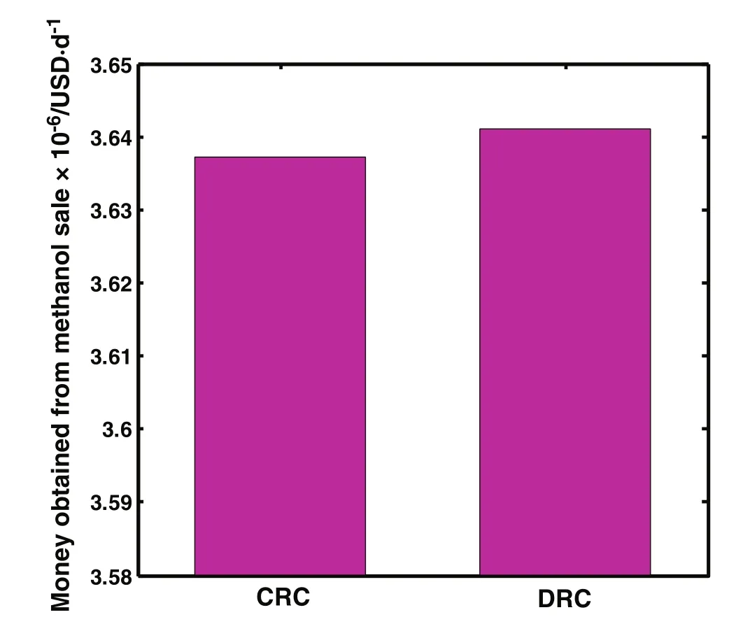
Fig.7.Comparison of money obtained from methanol sale per day in CRC and DRC.
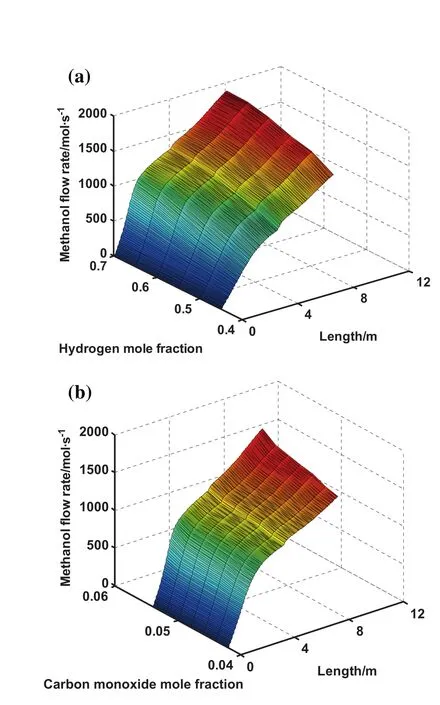
Fig.8.Effect of(a)hydrogen mole fraction and(b)carbon monoxide mole fraction on methanol production rate and reactor length.

Fig.9.Effect of hydrogen mole fraction on carbon dioxide production rate and reactor length.
RSM is utilized in order to optimize the methanol feed stream and operating conditions in the current study.The independent variables in this research are temperature(A),carbon dioxide flow rate(B),carbon monoxide flow rate(C)and hydrogen flow rate(D)which are given in Table 3.Furthermore,maximizing methanol flow rate and minimizing carbon dioxide flow rate have been considered as an objective function.
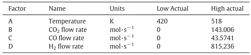
Table 3Domain of independent variables in RSM design
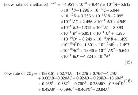
Design of experiment is based on levels of the independent variables resulted in 273 simulation runs.Eqs.15 and 16 present the fitted model that is able to provide a good fitness of the measured methanol and carbon dioxide production data,respectively.As clearly seen,the first parameter in these equations is the intercept and there are various coefficients which represent the effect of each factor as well as factor interactions.
Predicted values versus observed values for methanol and carbon dioxide are plotted in Fig.10(a)and(b),respectively.As obviously,the simulated values are in agreement with the predicted ones.Moreover,the values which are not simulated by the simulator can be predicted by Eqs.(15)and(16).
Internally studentized residuals as a function of fitted values for methanol and carbon dioxide are illustrated in Fig.11(a)and(b),respectively.No unusual structure is observed in these figures.These results show that the proposed model is sufficient.
Analysis of variance(ANOVA)has been applied for each parameter to identify the significance of the effects and interactions between the parameters.Moreover,a p-value less than 0.05 has been statistically considered significant.Design Expert(version 7)has been utilized for ANOVA and regression coefficient calculation.The important terms for the production of methanol and carbon dioxide are tabulated in Tables 4 and 5,respectively.These tables propose that the domain for all variables,which are considered in this model,present maximum methanol production and minimum carbon dioxide production with no significant change in the output and no change in any other variables.
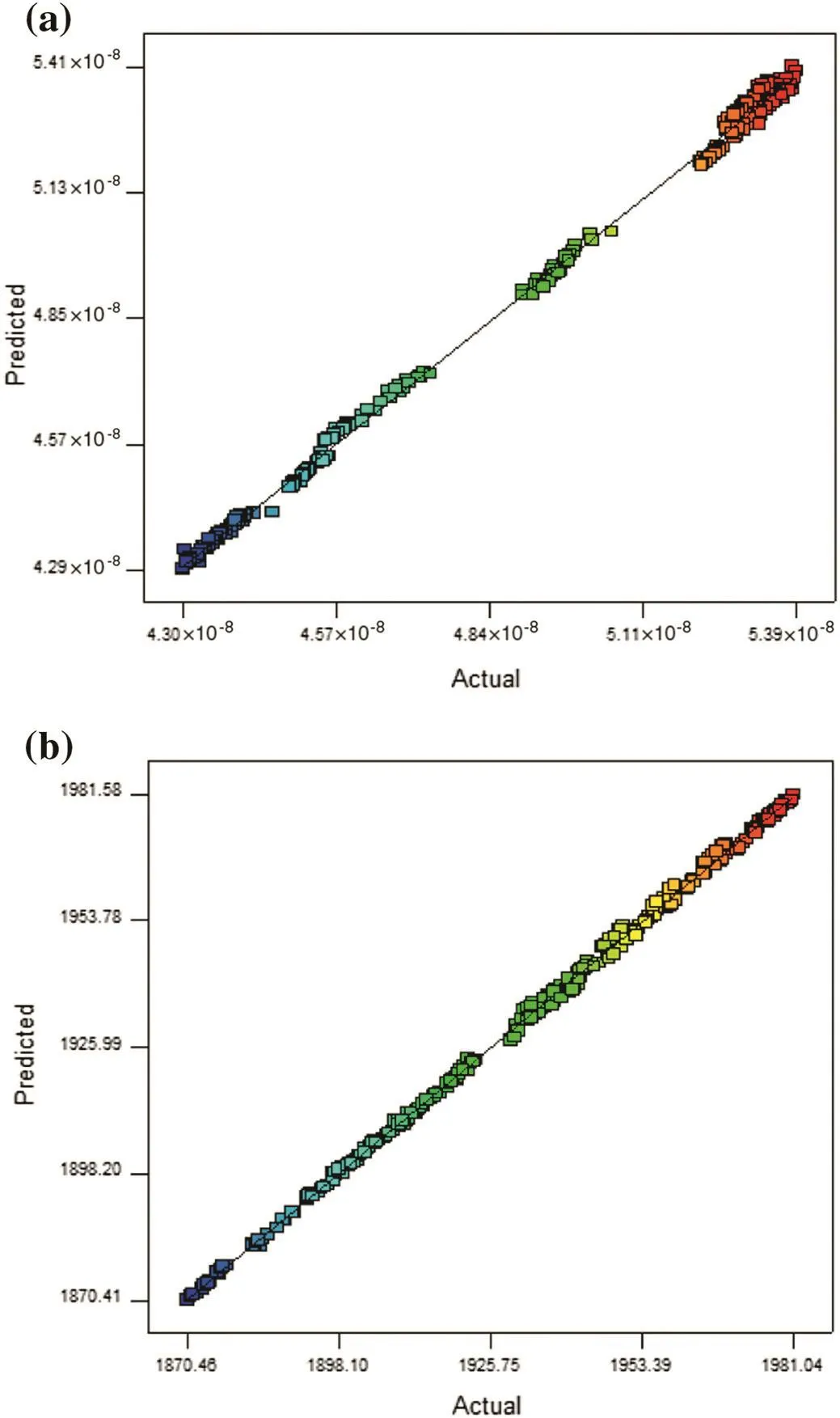
Fig.10.Normal probability plots of residual for(a)methanol and(b)carbon dioxide.
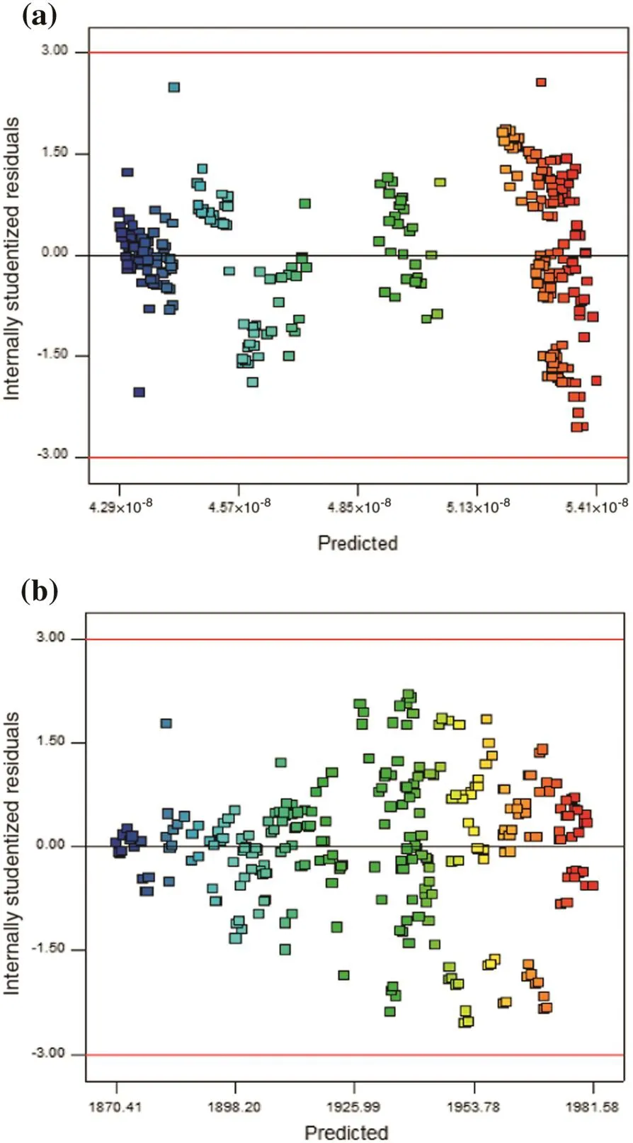
Fig.11.Plots of residual vs. fitted values for(a)methanol and(b)carbon dioxide.
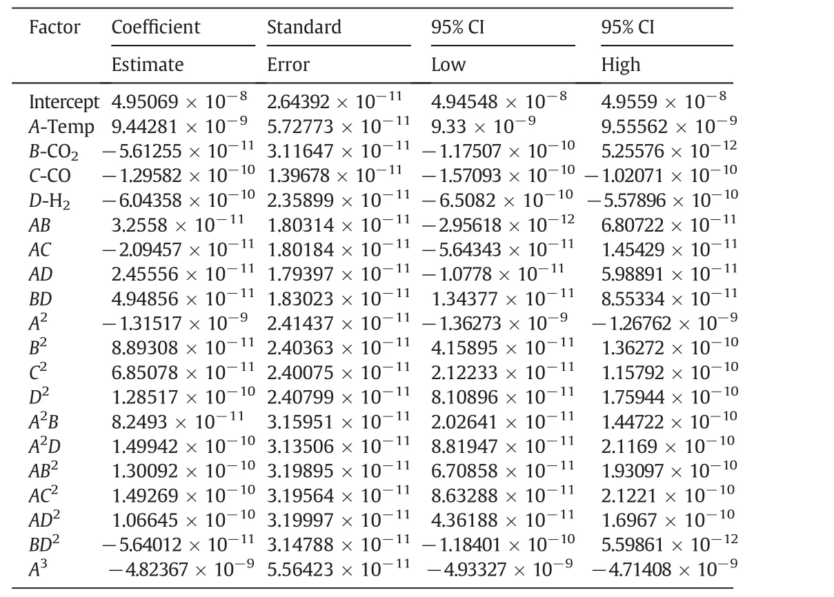
Table 4Model coefficients and the statistical interference of the effect of single variables and their interactions on the mean value of the estimated methanol production rate
The simultaneous effects of temperature and carbon dioxide flow rate on the production rates of methanol and carbon dioxide are depicted in Fig.12(a)and(b),respectively.Fig.12(a)shows that at first as the temperature increases,methanol production grows slightly and then it decreases.Subsequently,methanol production remains stable with increasing temperature at the end of the reactor.However,the inlet flow rate of carbon dioxide has no effect on the production of methanol.Fig.12(b)illustrates that simultaneous increase in temperature and inlet flow rate of carbon dioxide leads to increasing in the produced carbon dioxide.Therefore,it can be concluded that the effect of temperature on the production of methanoland carbon dioxide is greater than the input amount of carbon dioxide.
Fig.13(a)and(b)shows the simultaneous effects of hydrogen flow rate and carbon monoxide flow rate on the methanol production rate and carbon dioxide production rate,separately.Fig.13(a)depicts that the increase in the input flow rate of both hydrogen and carbon monoxide causes the increase in the rate of methanol production.But what stands out from the figure is that the impact of the input amount of hydrogen on the methanol production rate is higher than the input amount of carbon monoxide.Fig.13(b)shows that with increasing the input flow rate of hydrogen,carbon dioxide production rises and with the increase in input flow rate of carbon monoxide,carbon dioxide production goes up slightly.Consequently,the inlet amount of hydrogen has a significant in fluence on the production of methanol and carbon dioxide.
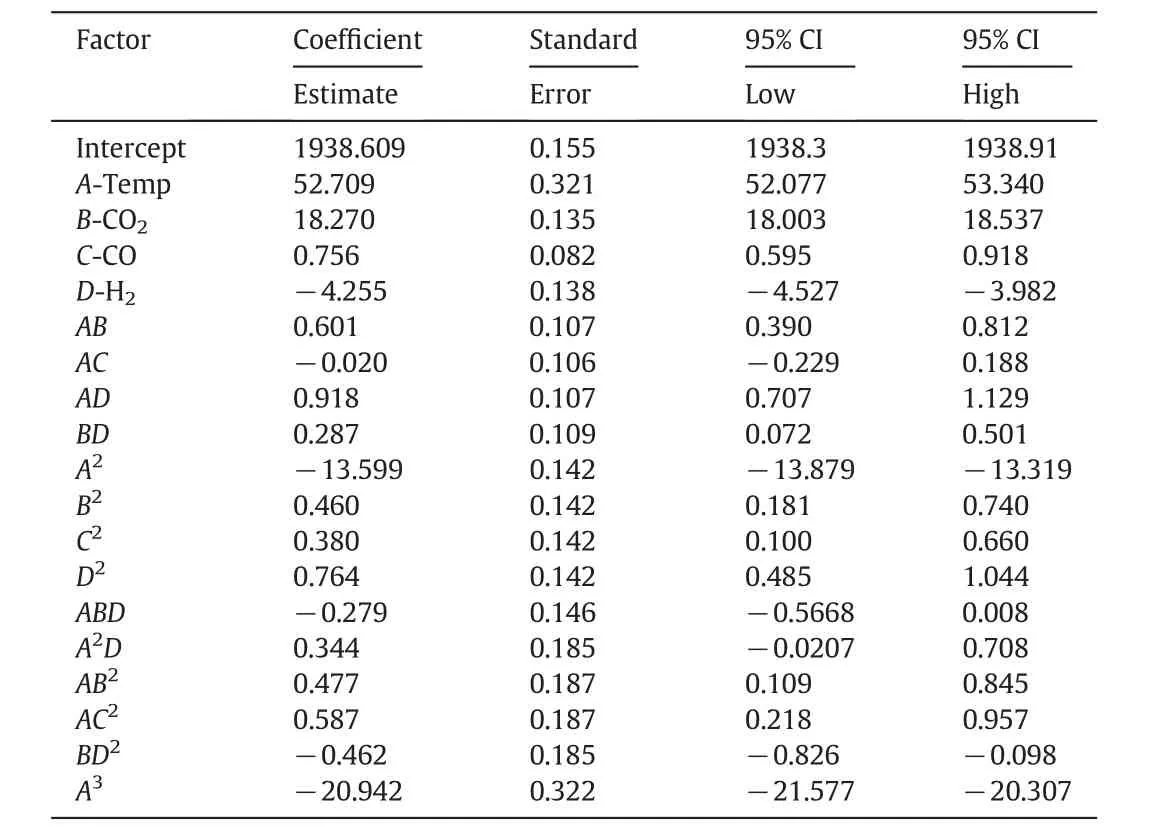
Table 5Model coefficients and the statistical interference of the effect of single variables and their interactions on the mean value of the estimated carbon dioxide production rate
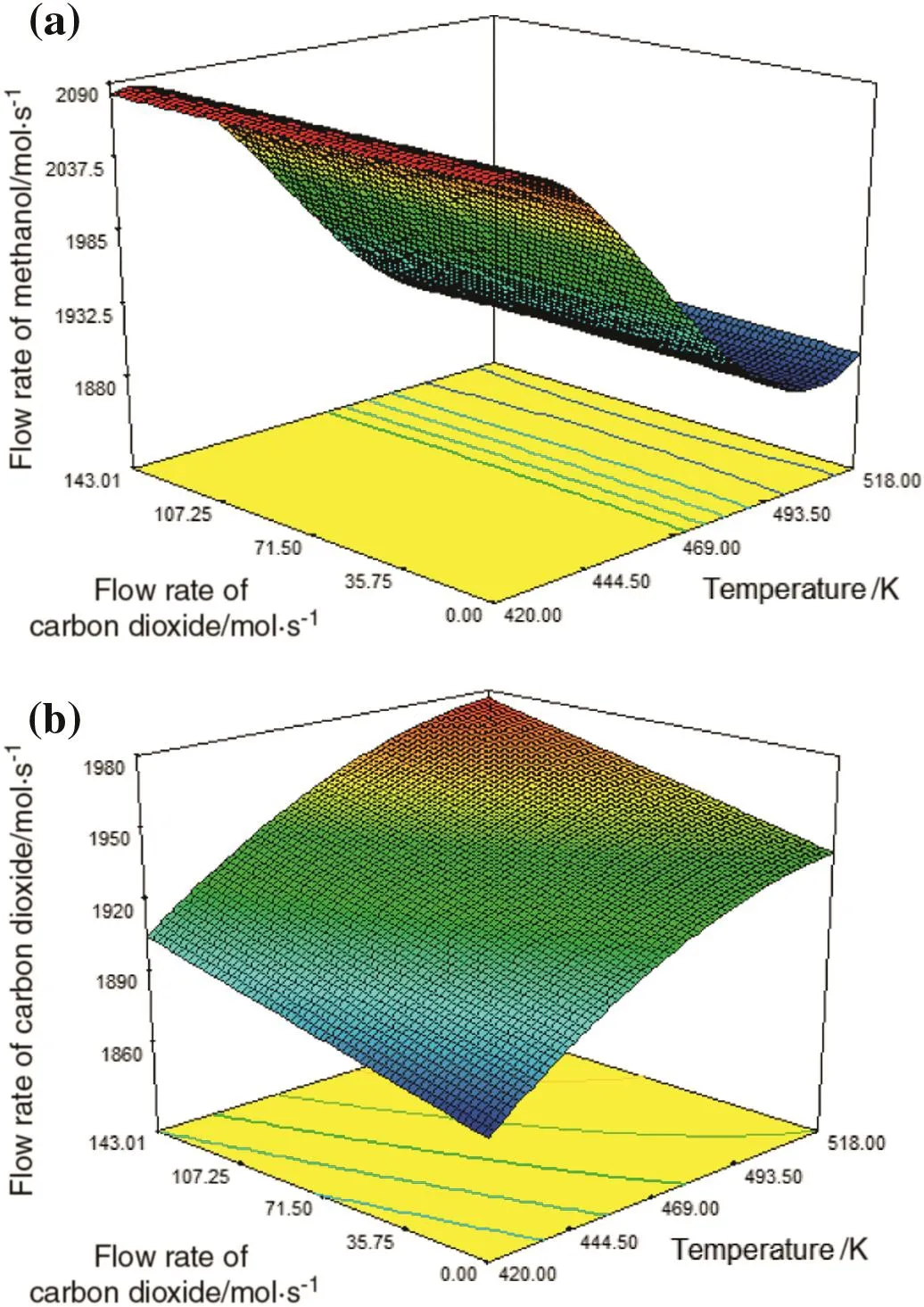
Fig.12.Simultaneous effects oftemperature and carbon dioxide flowrate on(a)methanol production and(b)carbon dioxide production.
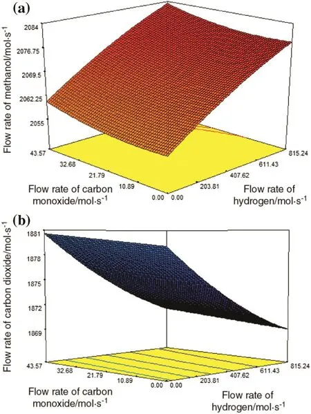
Fig.13.Simultaneous effects of hydrogen and carbon monoxide flow rates on(a)methanol production and(b)carbon dioxide production.
Optimized factors which are obtained by RSM for achieving maximum methanol flow rate and minimum carbon dioxide flow rate have been proposed in Table 6.Maximum methanol flow rate of 2083.61 mol·s?1and minimum carbon dioxide flow rate of 1870.46 mol·s?1are achieved when the inlet temperature of reactor is 420.502 K and the inlet flow rates of carbon dioxide,carbon monoxide and hydrogen are 0.01789,43.5661 and 815.11 mol·s?1,in turn.

Table 6A set of optimized factors obtained by RSM for achieving maximum methanol flow rate and minimum carbon dioxide flow rate
8.Conclusions
The purge gas of methanol unit in Iran petrochemical companies is used in two ways which do not have impact on the increase of methanol production rate.However,these purge gas streams contain the unreacted gases of methanol reactor feed stream.Furthermore,a large amount of money has been spent for producing them in the reforming unit.Therefore,the valuable components of such purge gas streams can be utilized as a feed of methanol synthesis rector.There are different con figurations which can be applied for recycling the components of purge streams to the feed stream.The Desired Recycle Con figuration(DRC)has been investigated in this study.Carbon monoxide,carbon dioxide and hydrogen are the optimal components which can be recycled from purge streams to the methanol feed stream for the purpose of achieving maximum methanol flow rate and minimum carbon dioxide flow rate in the outlet of the reactors.For the reduction of accumulation of nitrogen and methane in the reactor,it is suggested that they are separated from the gas mixture,because the presence of these two inert components in the reactor leads to the reduction of methanol production rate.As a result,a separation unit has been proposed in order to separate these components from the other components in the gas mixture of purge streams.The separation unit includes Pd–Ag and carbon nanotube membranes.By recycling carbon monoxide,carbon dioxide and hydrogen,the methanol flow rate increases approximately by 0.106%in DRC compared to CRC.Furthermore,the difference between the cost obtained from the methanol sale in DRC and CRC is about 3763.649USD·d?1.These results show the superiority of DRC to recycling the other components.In addition,the temperature and the molar flow rates of inlet components such as carbon dioxide,carbon monoxide and hydrogen are optimized by RSM which is one of the best and efficient optimization methods.Obtaining maximum value of methanol flow rate as a desired product and also minimum value of carbon dioxide flow rate as a destructive and detrimental component for the environment are the objective functions of RSM.As a matter of fact,10.83%increase in the methanol production rate and 4.078%decrease in the carbon dioxide production rate have been obtained by optimization.
Nomenclature
Accross section area of each tube,m2
avspecific surface area of catalyst pellet,m2·m?3
Cpspecific heat of gas at constant pressure,J·mol?1·K?1
ctotal concentration,mol·m?3
Didiameter of membrane,m
Epactivation energy of permeability,kJ·kmol?1
FTotal molar flow rate,mol·s?1
fifugacity of componenti,Pa
ΔHf,ienthalpy of formation of componentiJ·mol?1
ΔHienthalpy of reaction
hfgas–solid heat transfer coefficient,W·m?2·K?1
JCNTpermeation rate through the CNT membrane,mol·m?1·s?1
JPd-Agpermeation rate of hydrogen through the Pd-Ag membrane,mol·m?1·s?1
Kiadsorption equilibrium constant of speciesiMPa?1
KP,jequilibrium constant of reactionj
kgmass transfer coefficient for componenti,m·s?1
kireaction rate constant of speciesi
Lreactor length,m
Ptotal pressure(for exothermic side:Pa;for endothermic side:Pa
P0the pre-exponential factor,mol·m?2·s?1·Pa?0.5
ppartial pressure of componenti,Pa
Runiversal gas constant,J·mol?1·K?1
rireaction rate of componenti,mol·kg?1·s?1
Ttemperature,K
Uoverall heat transfer coefficient between exothermic and endothermic sides,W·m?2·K?1
yimole fraction of componenti,mol·mol?1
zaxial reactor coordinate,m
α permeation rate constant,mol·m?1·s?1·Pa?1/2
ρ density of fluid phase,kg·m?3
η catalyst effectiveness factor
π 3.1416
Superscripts
g In the bulk of gas phase
s At the surface of catalyst
Subscripts
0 inlet conditions
ichemical species
[1]M.R.Rahimpour,S.M.Jokar,Feasibility of flare gas reformation to practical energy in Farashband gas re finery:No gas flaring,J.Hazard.Mater.209-210(2012)204–217.
[2]M.Farniaei,M.Abbasi,A.Rasoolzadeh,M.R.Rahimpour,Enhancement of methanol,DME and hydrogen production via employing hydrogen perm-selective membranes in a novel integrated thermally double-coupled two-membrane reactor,J.Nat.Gas Sci.Eng.14(2013)158–173.
[3]G.H.Graaf,P.J.J.M.Sijtsema,E.J.Stamhuis,G.E.H.Joosten,Chemical equilibrium in methanol synthesis,Chem.Eng.Sci.J.41(11)(1986)2883–2890.
[4]N.Kuczynski,M.H.Oyevaar,R.T.Piters,K.R.Westerterp,Methanol synthesis in a counter-current gas–solid–solid trickle flow reactor:an experimental study,Chem.Eng.Sci.J.42(8)(1987)1887–1889.
[5]N.Park,M.J.Park,Y.J.Lee,K.S.Ha,K.W.Jun,Kinetic modeling of methanol synthesis over commercial catalysts based on three-site adsorption,Fuel Process.Technol.125(2014)139–147.
[6]M.R.Rahimpour,S.Ghader,Enhancement of CO conversion in a novel Pd–Ag membrane reactor for methanol synthesis,Chem.Eng.Process.43(9)(2004)1181–1188.
[7]M.R.Rahimpour,M.Lot finejad,Enhancement of methanol production in a membrane dual-type reactor,Chem.Eng.Technol.30(8)(2007)1062–1076.
[8]J.H.Edwards,N.R.Foster,The potential for methanol production from natural gas by direct catalytic partial oxidation,Fuel Sci.Technol.Int.4(4)(1986)365–390.
[9]G.E.P.Box,K.B.Wilson,On the experimental attainment of optimum conditions(with discussion),J.R.Stat.Soc.Ser.B13(1)(1951)1–45.
[10]C.Songa,Y.Kitamurab,S.Lib,Optimization of a novel cryogenic CO2capture process by response surface methodology(RSM),J.Taiwan Inst.Chem.Eng.45(4)(2014)1666–1676.
[11]S.Toemen,W.A.Wan Abu Bakar,R.Ali,Investigation of Ru/Mn/Ce/Al2O3catalyst for carbon dioxide methanation:Catalytic optimization,physicochemical studies and RSM,J.Taiwan Inst.Chem.Eng.45(5)(2014)2370–2378.
[12]G.F.Silva,F.L.Camargo,A.L.O.Ferreira,Application of response surface methodology for optimization of biodiesel production by transesterification of soybean oil with ethanol,Fuel Process.Technol.92(3)(2011)3407–3413.
[13]Y.Wu,S.Zhou,F.Qin,X.Ye,K.Zheng,Modeling physical and oxidative removal properties of Fenton process for treatment of land fill leachate using response surface methodology(RSM),J.Hazard.Mater.180(1–3)(2010)456–465.
[14]X.Duan,Z.Zhang,C.Srinivasakannan,F.Wang,J.Liang,Regeneration of spent catalyst from vinyl acetate synthesis as porous carbon:Process optimization using RSM,Chem.Eng.Res.Des.92(7)(2014)1249–1256.
[15]F.Samimi,Z.Khadem Modarresi,O.Dehghani,M.R.Rahimpour,A.Bolhasani,Application of response surface methodology for optimization of an industrial methylacetylene and propadiene hydrogenation reactor,J.Taiwan Inst.Chem.Eng.46(2015)51–64.
[16]I.Noshadi,N.A.S.Amin,S.Parnas,Continuous production of biodiesel from waste cooking oil in a reactive distillation column catalyzed by solid hetero poly acid:Optimization using response surface methodology(RSM),Fuel94(2012)156–164.
[17]J.Kumar,A.Bansal,Photo catalytic degradation in annular reactor:Modelization and optimization using computational fluid dynamics(CFD)and response surface methodology(RSM),J.Environ.Chem.Eng.1(2013)398–405.
[18]S.Kumar,R.K.Singh,Optimization of process parameters by response surface methodology(RSM)for catalytic pyrolysis of waste high-density polyethylene to liquid fuel,J.Environ.Chem.Eng.2(2014)115–122.
[19]M.Takht Ravanchi,T.Kaghazchi,A.Kargari,Application of membrane separation processes in petrochemical industry:A review,Desalination235(1–3)(2009)199–244.
[20]D.Saha,Z.Bao,F.Jia,S.Deng,Adsorption ofCO2,CH4,N2O,and N2on MOF-5,MOF-177,and zeolite 5A,Environ.Sci.Technol.44(5)(2010)1820–1826.
[21]J.Lindmark,J.Hedlund,Carbon dioxide removal from synthesis gas using Mfi membranes,J.Membr.Sci.360(1–2)(2010)284–291.
[22]K.Salehi,S.M.Jokar,J.Shariati,M.Bahmani,M.A.Sedghamiz,M.R.Rahimpour,Enhancement of CO conversion in a novel slurry bubble column reactor for methanol synthesis,J.Nat.Gas Sci.Eng.21(2014)170–183.
[23]F.Su,C.Lu,W.Cnen,H.Bai,J.F.Hwang,Capture of CO2from flue gas via multi-walled carbon nanotubes,Sci.Total Environ.407(8)(2009)3017–3023.
[24]G.H.Graaf,H.Scholtens,E.J.Stamhuis,Intra-particle diffusion limitations in lowpressure methanol synthesis,Chem.Eng.Sci.45(4)(1990)773–783.
[25]M.Bayat,M.R.Rahimpour,Simultaneous production of ultrapure hydrogen and gasoline in a novel thermally coupled double membrane reactor,Int.J.Energy Res.37(1)(2013)35–48.
[26]G.P.Rangaiah,Multi-Objective Optimization:Techniques and Applications in Chemical Engineering,National University of Singapore,Singapore,2008.
 Chinese Journal of Chemical Engineering2017年5期
- Chinese Journal of Chemical Engineering的其它文章
- The effect of transition metal ions(M2+=Mn2+,Ni2+,Co2+,Cu2+)on the chemical synthesis polyaniline as counter electrodes in dye-sensitized solar cells☆
- Catalytic ozonation of thymol in reverse osmosis concentrate with core/shell Fe3O4@SiO2@Yb2O3 catalyst:Parameter optimization and degradation pathway☆
- Influence of Na+,K+,Mg2+,Ca2+,and Fe3+on filterability and settleability of drilling sludge☆
- Partition coefficient prediction of Baker's yeast invertase in aqueous two phase systems using hybrid group method data handling neural network
- Solubility and metastable zone width measurement of 3,4-bis(3-nitrofurazan-4-yl)furoxan(DNTF)in ethanol+water
- Measurement and calculation of solubility of quinine in supercritical carbon dioxide☆