
Numerical investigation of the concentric annulus flow around a cylindrical body with contrasted effecting factors*
2015-04-20 05:52:54ZHANGXuelan張雪蘭SUNXihuan孫西歡LIYongye李永業(yè)XIXianan郗夏楠GUOFei郭飛ZHENGLijian鄭利劍
水動力學(xué)研究與進(jìn)展 B輯 2015年2期
關(guān)鍵詞:利劍
ZHANG Xue-lan (張雪蘭), SUN Xi-huan (孫西歡),2, LI Yong-ye (李永業(yè)), XI Xia-nan (郗夏楠),GUO Fei (郭飛), ZHENG Li-jian (鄭利劍)
1. College of Water Resource and Engineering, Taiyuan University of Technology, Taiyuan 030024, China,E-mail: hbxiehou@126.com 2. Shanxi Conservancy Technical College, Yuncheng 044004, China 3. Xi’an Water Conservancy Planning and Survey Designing Institute, Xi’an 710001, China
Introduction
In most of the previous investigations of the flow around cylinders, the cross flow over cylinders was involved and the lengths of these cylinders were mostly considered as infinite. Under these conditions, the flows over a single cylinder of different types and multi-cylinders of various arrangements and sizes(equal or unequal) were studied. Many qualitative results about the flow pattern and the force statistics were obtained, illustrating the formation mechanisms of the vortex shedding and the complex flow field.
Farrant et al.[1]and Behzad and Abolfazl[2]studied the flow around two cylinders (or circular piers)in the tandem array and the side-by-side array to show the variations of forces and what happens in downstream regions. Kang[3]observed six kinds of wake patterns in his two-dimensional numerical simulation of the flow around two cylinders side-by-side at low Reynolds numbers using the immersed boundary method. Harichandan and Roy[4]simulated the flow over two and three cylinders in the two arrangements using the unstructured grid CFR scheme. In their investigation, different wake patterns, including the flip-flopping, deflected patterns, the in-phase and anti-phase synchronized patterns and the steady patterns, were observed depending on the Reynolds number and the gap spacing. As the diameter of the upstream cylinder is reduced, it becomes an attaching rod fot the drag reduction. Zhang et al.[5]presented several flow patterns between the rod and the cylinder, with an increasing gap spacing at different rod sizes. He also discussed the relationship between the system drag redu-ction and the spacing ratiosL/D0(whereLis the spacing between the centers of the rod and the main cylinder,D0is the diameter of the cylinder). Wang et al.[6]studied the drag reduction of a circular cylinder with an upstream rod in a limited angleα(whereαis the staggered angle between the rod and the cylinder).
When there are more than two cylinders, more types of cylinder arrangements might be assumed for the composite flow. Bao et al.[7]performed a detailed investigation using three cylinders with equilateral arrangements. It is shown that the vortex shedding behind cylinders is similar to that behind a bluff body due to the proximity effect when the spacing gap between cylinders is small. A combination effect of the wake and the proximity complicates the wake structure for an intermediate gap spacing of 2D0. When the gap space further increases, the wake effect turns to be the main part of the interference. Farrant et al.[8]carried out simulations of the laminar flow around four cylinders using the cell boundary method and the finite volume method, respectively atRe=200. Lam et al.[9]discussed the relation between the flow characteristics and the spacing ratios atRe=100 andRe=200 with 2-D and 3-D simulations to calculate the flow around four cylinders in an in-line square configuration. To show the flow features at high Reynolds numbers,Lam and Zou[10]numerically calculated the flow around four cylinders in an in-line array atRe=1.5×10⁴using the Large Eddy Simulation. The calculation shows a distinct vortex shedding behind upwind cylinders and a bi-stable flow nature at spacing ratios of 3.5 and 1.5, respectively. Recently, the number of cylinders contained in investigations has been increased.Bao et al.[11]applied an in-line array of six square cylinders atRe=100. Yang et al.[12]arranged a main cylinder of a large size and six surrounding cylinders of small diameters to carry out the vortex shedding study.Huang et al.[13]performed the simulation of the laminar flow around two rows of cylinders to show formations of Kaman vortices. It is shown that the incomplete vortex shedding occurs behind the first row instead of the Kaman vortex formation when the cylinders are arranged in two inline rows and the separation distance is less than 2D0.
Besides, the computational boundary in a limited calculation domain is another factor that influences the flow structures. Compared with the free stream,the wall-bounded flow has different flow features owing to the interferences from the cylinders and the boundaries[14]. When the cylinders are placed in a pipe,the pipe flow will turn to be a wall-bounded turbulent flow due to the sudden disturbance. For the pipe turbulence pattern, the classical assumption about the mean velocity in the fully developed pipe flow is a logarithmic variation[15]. And there were two prototypical extensions proposed. One extension concerns the intermediated “mesolayers” to form the classical inner and outer layers, as proposed by Wei et al.[16]. Wosnik et al.[17]proposed another type of extension of the logarithmic variation with a shifted origin at low Reynolds numbers. Besides the two extensions, a main alternative of the logarithmic variation was proposed. Barenblatt[18]pointed out that the mean velocity obeys a power law with Re-dependent exponents both in the boundary layers and the pipe with consideration of the effects of the Reynolds numbers.
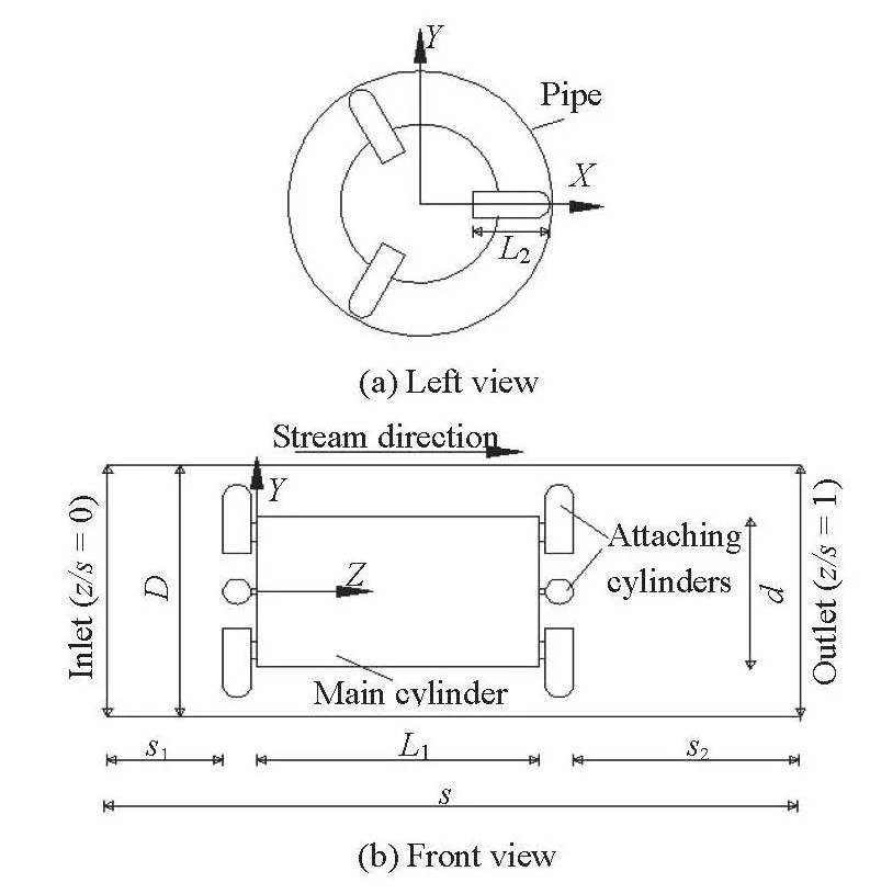
Fig.1 Schematic diagrams of the simulation model
To further explore the stream domains and the flow spaces, a cylindrical body, consisting of a main cylinder of a large diameter and six small attaching cylinders of equal sizes, located in a straight pipe, is considered in the present investigation. Some improvements as compared with the previous investigations are made. Firstly, six attaching cylinders are arranged with a radial distribution on the two end faces of the main cylinder. And a vertical relationship exists between the axes of the two kinds of cylinders of limited lengths. Secondly, the cylindrical body is located in a straight pipe of a limited diameter. The axes of the main cylinder and the pipeline are coincident to form a concentric annulus space. Thirdly, the pipe wall makes the flow around the cylindrical body a wallbounded flow and the sudden disturbance makes the pipe flow turn to be turbulent. Finally, the cylindrical body located in the straight pipe is a generalized arrangement in the process of a new type of pipe transportation. The knowledge of the flow field is useful for the improvement of the transportation. According to the above discussions, the complex flow should be further investigated to show the flow structure and the hydraulic characteristics of the flow field. Unlike the previous investigation of the concentric flow based onexperiments[19], this investigation will be mainly carried out by numerical simulations. Zhang et al.[20]discussed the flow field structure of the concentric annulus flow around the cylindrical body in the straight pipe by simulation. In this paper, the concentric annulus flow around the cylindrical body with contrasted effecting factors will be studied further using the munerical method to show special characteristics of the flow field.
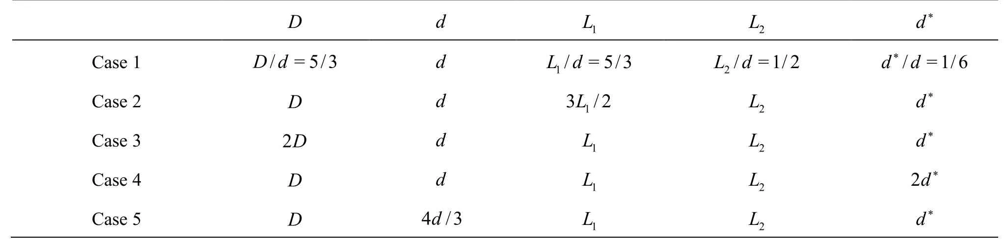
Table 1 Parameters of calculation models in all cases
1. Simulation model and numerical tool
The geometry of the cylindrical body is designed as a generalized model of a transport carrier in the hydraulic transport in the pipeline. The investigation of this geometry serves as a foundation for the improvement of the transportation. The schematic diagram of the simulation model, containing the pipe and the cylindrical body, is illustrated in Fig.1, in the left view and the front view of the model, where related parameters are shown. The structure of the cylindrical body, located in the pipe along the pipe axis, mainly consists of two parts: the main cylinder with diameterdand six attaching cylinders with diameterd*. On each end of the main cylinder, three attaching cylinders are arranged in a radial distribution with an interval angle ofo120 between two neighboring ones. The mini sheets are arranged between the main cylinder and the attaching cylinders to connect the two parts.The six attaching cylinders, contacting with the pipe wall and distributing in the radial arrangement, is to support the main cylinder in the pipe to form an annulus space for the stream. In the present investigation,an original simulation model (denoted as Case 1) is designed and several models with different parameters(denoted as Cases 2, 3, 4, 5) are compared. In the original simulation model, the length of the main cylin der isL1=5d/3 and that for the attaching cylinder isL2=d/2. The ratio of the diameters of the two types of cylinders isd*/d=1/6. The pipe is a straight one with the inner diameterD=5d/3. Owing to the coincident axes of the pipe and the main cylinder,a concentric annulus space around the main cylinder is formed, and the computational flow in the pipe is named as the concentric annulus flow. One end of an attaching cylinder, near the pipe wall, is a semi-sphere,whose diameter is equal to that of the attaching cylinder. A Cartesian coordinate is established in the model. The coordinate origin is placed at the center of the upstream end of the main cylinder and the positive direction ofZ-axis is along the stream direction.These compared models are in the same kind of arrangements with parameters given in Table 1. In Case 2,Case 4 and Case 5, the parameters of the cylindrical body are different. And the inner diameter of the pipe is larger in Case 3.
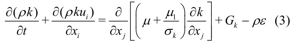
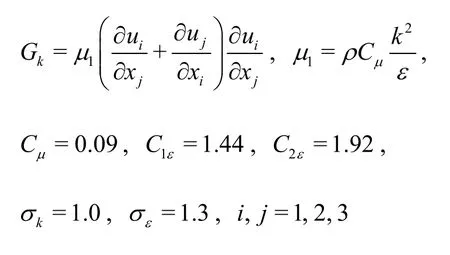
Based on the previous studies of annulus flows,including experimental and numerical investigations,the flows at five Reynolds numbers (denoted asRe1=7.67×10⁴,Re2=1.02× 10⁵,Re3=1.28× 10⁵,Re4=1.53×10⁵,Re5=1.79× 10⁵) are simulated and our numerical tools are tested. Various effecting factors are considered atRe3=1.28× 10⁵. Due to the high Reynolds number, the turbulence flow is assumed in the 3-D numerical simulation. According to the investigation purpose and the computational efficiency,the high Reynolds standardk-εmodelis adopted in these numerical calculations. The governing equations are as follows:
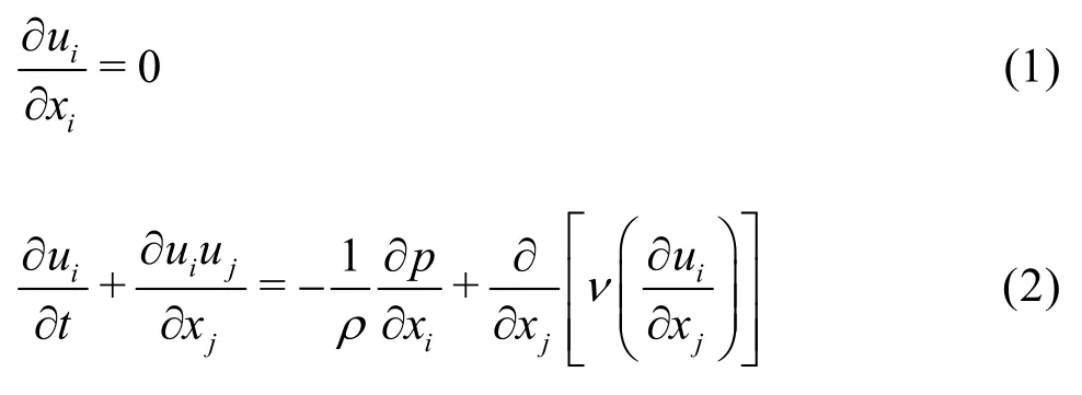
whereνis the kinematic viscosity, andρis the density of the fluid.Two transport equations corresponding to the unknown parameters (kandε) in the standardk-εmodel are
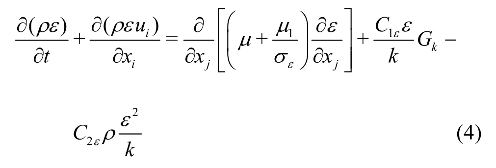
where
In the present numerical investigation, the SIMPLEC scheme with second order accuracy in Fluent 6.3 is adopted. The selection of the SIMPLEC scheme is because its feature of under-relaxation accelerates the convergence rate. The main computational domain iss=s1+s2+L1+2d*. An unsteady incompressible fluid flow of constant density and viscosity goes from the initial condition of mean velocityU=U0in the inlet,s1=10daway from the upstream end of the cylindrical body. The turbulent kinetic energykinand the turbulent dissipation rateεinin the inlet are given as
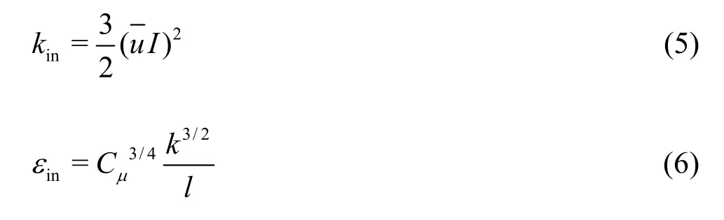
where the turbulent intensity is obtained byI=0.16·(ReD)-1/8(whereReDis the Reynolds number based
on the hydraulic diameter), and the turbulence length scale isl=0.07Din a circular pipe. The outlet,s2=20daway from the downstream end of the body,is configured as the “pressure-outlet”. The wall roughness heightsKsand the roughness constantsCkof both cylinders and the pipe are set as 10-5m and 0.5,respectively, based on the material of plexiglass. The grid system in each simulation is generated, with the interval size of 0.5 for the volume grid to balance the calculation efficiency and the accuracy and withy+suitably selected for the wall function. Take Case 1 as an example to give an illustration.y+=131 <200 means that the selected standard wall function is suitable for the simulation. In these simulations, the iterating time steps are 500 with step size of 0.005 and all iterations are converged, where the residuals in all equations are less than 0.001, and the flow develops fully with sufficient data for the investigation.
In the investigation, the pressure distributions and the flow patterns in different cases, and some global parameters, including the drag coefficient (Cd)and the lift coefficient (Cl), are discussed. These two parameters are defined as follows:
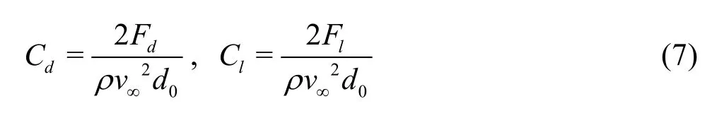
whereFdis the drag force inZ-direction andlFis the lift force inY-direction, respectively.v∞andd0are the characteristic velocity and the diameter, respectively.
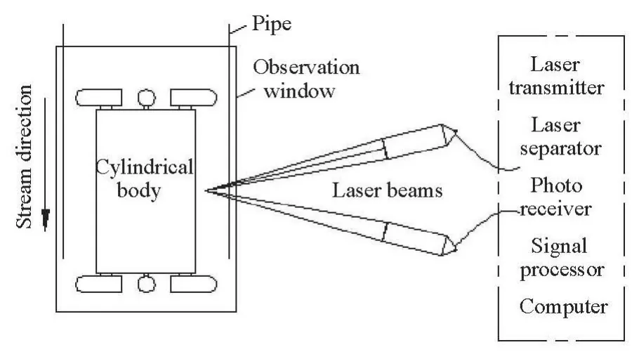
Fig.2 Schematic diagram of experimental arrangement in velocity testing
2. Numerical tool validation
For the purpose of validating the numerical calculations, experiments about the sectional velocity distributions and the pressure differences on the pipe wall are performed. The laser Doppler anemometry(LDA) measurement is used in the velocity testing of the concentric annulus flow. The experimental arrangement of the velocity testing is schematically illustrated in Fig.2. The LDA is a measuring technique to obtain the velocity at a point by detecting the frequency shift of the laser beam scattered by the particles suspended in the flow. With the test probes sending out laser beams, the LDA mainly involves five parts,which are given in the dashed box in the figure. The pressure sensors connected to the pressure taps, located at the intersection of the positiveX-axis, are adopted to measure the pressure drop of the pipe segment,which is between the sectionsz/s=0.267 andz/s=0.422 (wherezis the coordinate in theZ-axis direction). The pressure drops at five Reynolds numbers are, representatively, shown in Fig.3. Theinvestigated segment for the pressure drop just contains the cylindrical body, so the pressure drop is primarily produced by the local head loss due to the cylindrical body, ignoring the frictional head loss. In Fig.3(a), the numerical results and the experimental results of the pressure drop are compared. The velocity distributions on the positive axis in the two representative feature cross sections /=0.288satRe3, obtained by the present numerical simulation and the experiments, are compared in Figs.3(b) and 3(c), respectively. In these figures, some small differences exist between the numerical results and the experimental results, but the agreement is thought to be acceptable in view of the same distribution trend. Due to a certain distortion, caused by thezsandz/=0.345 assumption of the isotropic viscosity coefficient for each component of the Reynolds stress in the numerical model, which may occur in the flow simulations near the bending boundary, relatively larger differences are found for highery/D(whereyis the coordinate in theY-axis direction)than for the positions with lower values. The representative comparisons between these numerical results and experimental results show that the simulation is reliable for the investigation of the complex flow in the pipe.
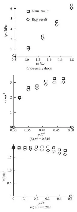
Fig.3 Validations of the pressure drops and velocity distributions
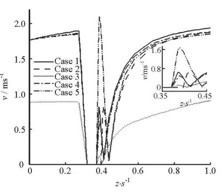
Fig.4 Velocity distribution along Z-axis in each case
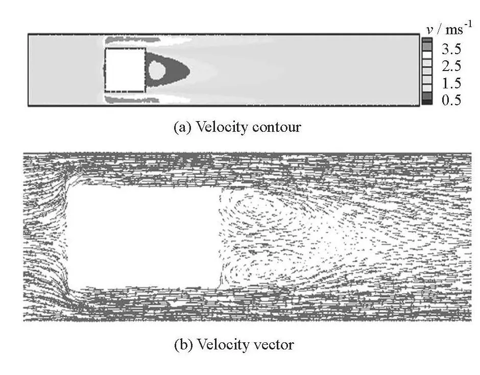
Fig.5 Velocity contours and vectors in section x/D=0 in Case 1
3. Numerical results
3.1 Velocity distribution along the pipe axis
Figure 4 shows the velocity distribution along the pipe axis (Z-axis in the coordinate system) in each case with a detailed illustration of the local segment of 0.35 / 0.48zs<<. There are velocity-vacancy segments in the range of 0.319 / 0.371s≤ in Case 2) due to the obstacle of the main cylinder. Besides, an up-down-up trend behind the velocity-vacancy segment exists in each case, which implies a sharp velocity fluctuation behind the main cylinder as illustrated in detail in Fig.5(a). As seen from the curve of Case 3, the velocity is much smaller than≤ ≤ (0.319≤z/0.396zsthose in other cases except in the velocity-vacancy segment, which is because the velocity in the enlarged flow cross section is decreased at a fixed Reynolds number = /ReUdν. In Case 5, the diameter of the main cylinder is increased to 4d/3. The updown range in the particular local segment is larger than in the other segments and a higher peak value appears in the area, which means that the main cylinder with a larger diameter leads to a wider area of velocity fluctuation behind the cylindrical body. In Case 2, the length of the main cylinder is increased. Thus, the range of velocity-vacancy is larger, but the highest value and the lowest value are unchanged in the local section. This phenomenon illustrates that the changed length of the main cylinder leads to a panning effect on the following local flow without changing the flow structure. Compared with the velocity distribution in Case 1, a small difference appears in Case 4, which means that the change of the diameter of attaching cylinders hardly produces a strong effect on the velocity distribution along the pipe axis. Based on the above analysis, the impacts of different factors on the velocity distribution along the axis are shown. The analysis supplies a preliminary understanding for further discussions in the plane analysis of the flow pattern.
Figure 5(a) shows the velocity contours of sectionx/D=0 (wherexis the coordinate in theX-axis direction) in Case 1 to illustrate the sectional velocity distribution for a further supplement for Fig.3.In the 2-D velocity distribution, a tongue-shaped wake is found behind the main cylinder, with an approximately circular zone of higher velocities than the surrounding values being nested inside. So there is a peak value, which is located in the nested zone, in each-Zaxial velocity distribution curve in Fig.4. In the outside of the nested zone, the velocity increases gradually along the axial flow direction in the pipe and the tongue-shaped wake disappears with the increasing velocity. In front of the main cylinder, there is also a small low velocity region due to the chocked flow effect. In Fig.5(a), two high velocity regions can be seen above and below the main cylinder, which can be easily understood according to the formula ofQ=AV. As the fluid flows into the annulus around the main cylinder, the cross section for the flow is shrunk suddenly and the velocity rises up correspondingly.Meanwhile, the viscous effects due to the pipe wall and the main cylinder wall make the velocity in the annulus core higher than that in the region near the wall. Similar to the tongue wake, the high velocity zone in the annulus vanishes gradually with the flow redistribution due to the sudden disturbance of the cylindrical body. In Fig.5(b), the velocity vectors in this section are indicated. Obviously, a pair of reversing zones appears behind the main cylinder. In front of the upstream end face of the cylinder, the flow direction is altered and the fluid flows into the annulus. Excepting for the two distinct locations, the velocity vectors in other spaces are parallel to the axial direction of the pipeline.
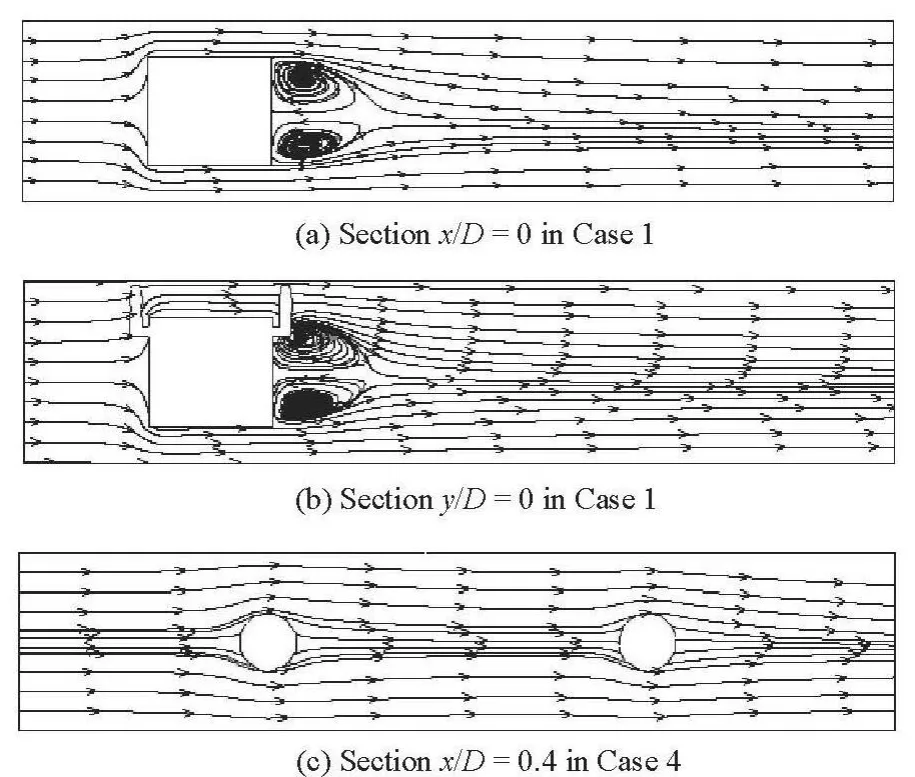
Fig.6 Streamlines in 2-D planes
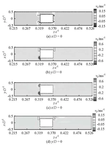
Fig.7 Contours of X-velocity and Y-velocity in sections of x/D =0 and y/D=0
For further understanding the flow pattern, the streamlines in the longitudinal sections at several situations are shown in Fig.6. Figures 6(a) and 6(b) show the streamlines in Case 1 and Fig.6(c) shows the streamlines in Case 4 to give a characteristic display ofthe flow. From Figs.6(a) and 6(b), one sees the reversing zones behind the cylinder, as is consistent with the vector plot. On the other hand, there is no reversing wake produced behind any attaching cylinder in Fig.6(c). In the figure, the flow around a pair of attaching cylinders on the upstream end face and the downstream end face of the main cylinder is shown, representatively. In all figures, the streamlines far away from the cylinders remain straight owing to the restriction of the pipe wall. The streamlines in other cases show similar appearances. Thus, it is concluded that the attaching cylinder in the limited calculation domain of the pipe at a high Reynolds number does not generate the classical flow around a circular cylinder with vortex shedding as in the free cross stream.
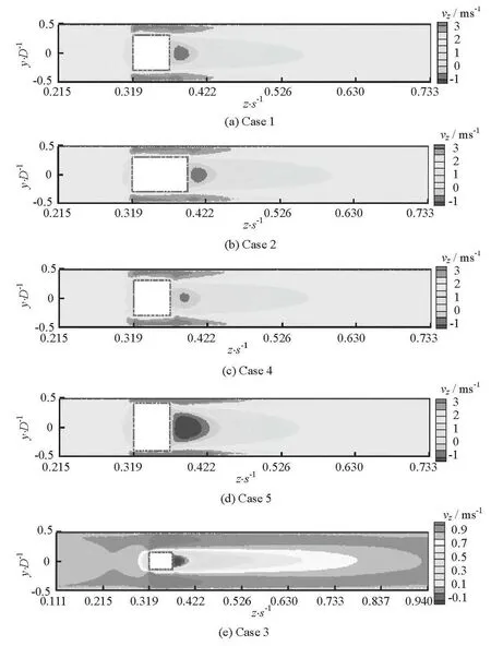
Fig.8 Contours of the axial velocity
3.2 Characteristics of velocities in three directions
The velocities in three directions (X,Y,Z-directions) need to be studied separately for a detailed understanding of the flow field around the cylindrical body. In Fig.7, the contours ofX-velocity (marked asvxin figures) andY-velocity (marked asvyin figures) in representative sections ofx/D=0 and/ =0yDin Case 1 are shown representatively. It is shown that the velocities in the two directions in the principal space of the calculation domain are at a low level of the absolute value. In regions near the edges of the end faces of the main cylinder and the surfaces of the attaching cylinders, one sees higher velocities than those in the surrounding space, due to the steering flow round the obstacle body. Thus, it is concluded that the axial direction (Z-direction) is the main velocity direction in the pipe. Then, the axial velocity contours in each case is shown in Fig.8.
Because the velocity levels are different in different areas of the pipe cross sections at the same investigated Reynolds number, while the velocity scales for contours in Cases 1, 2, 4, 5 (see Figs.8(a)-8(d)) are the same, the scales in Case 3 (see Fig.8(e)) are refined. In Fig.8(a), a basically similarZ-velocity(marked asvzin figures) distribution to the combinedvelocity distribution (in Fig.5(a)) is seen in the section.Compared with Fig.5(a), the difference in theZ-velocity distribution trend is that it increases from the tongue core to the outside region without a nested zone of higher velocities than the surrounding values.From the comparison ofZ-velocity contours between Case 2 and Case 1, it is shown that the ranges of the tongue wake and the annulus high velocity wake are prolonged without significant changes in the distribution pattern. The length variation of the main cylinder changes the affected range in the longitudinal direction. It is easily shown in the comparison between Case 4 and Case 1 that the area of the wake core with the lowest velocity is reduced. That is because of the more intense mixing effect from the flow passing the attaching cylinders with a larger size, that merges with the reversing wake behind the main cylinder and reduces the wake core area. And small convex parts are found in the front zone with low velocity and the annulus zone with high velocity next to the downstream end of the cylindrical body due to the attaching cylinders with enlarged diameters. On the other hand, in Case 5, the lowest velocity region in the wake zone is expanded, the width of the tongue wake is increased and the length is decreased due to the larger diameter of the main cylinder than in Case 1. And in the annulus, the core range with the highest velocity increases,which is because the cross section area of the annulus decreases as a result of the enlarged diameter of the main cylinder. In Case 3 (Fig.8(e)), the inner diameter of the pipe is much larger than that of the cylindrical body, and the annulus zones with high velocity and the wake with low velocity also exist in this situation.Due to the refined velocity scales, theZ-velocity distribution is shown in more detail. The length of the high velocity zone in the annulus is obviously smaller than others. The low velocity region gradually spreads to the whole cross section of the pipe, reversing the flow direction in a short segment. On the other hand,the tongue region disappears in a much longer segment behind the cylindrical body. In Fig.8(e), low velocities near the wall boundary owing to the wall viscous effect are clearly displayed.
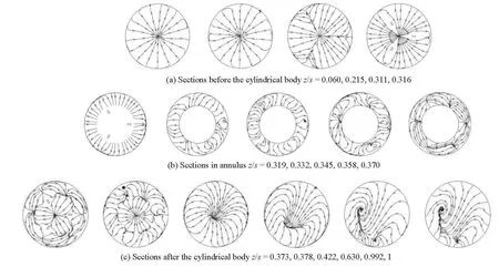
Fig.9 Streamlines in cross sections of the pipe domain
3.3 Streamline characteristics in cross sections
For the purpose of studying the flow patterns in cross sections in the pipe domain, the streamlines obtained by usingX-velocity andY-velocity in several sections in Case 1 are shown as an example in Fig.9. The sections (z/s=0.060, 0.215, 0.311, 0.316)in front of the cylindrical body are shown in Fig.9(a),the sections (z/s=0.319, 0.332, 0.345, 0.358, 0.370)in annulus are shown in Fig.9(b) and the sections (z/s=0.373, 0.378, 0.422, 0.630, 0.992, 1) behind the body are shown in Fig.9(c). In two cross sectionsz/s=0.060 and 0.215, the streamlines uniformly taper to the centers. Two streamlines would not intersest at a point under normal circumstances because the velocity direction must be unique at a point. Therefore, the intersection points in these figures mean zero velocities (combined byX-velocity andY-velocity) at the section centers. In the same way, the appearances of the streamline intersection in the following cross sections can be explained. Near the cylindrical body, the effect of the body shows gradually. In the sectionsz/s=0.311 and 0.316, the streamline distribution on each section turns to be divided into three parts andthe dividing edges follow the locations of the attaching cylinders. Unlike the former two sections, the streamlines diverge from the center, because the fluid flows towards the pipe wall to enter the annulus in the front neighboring region. Besides, the convergence lines appear as dividing edges in the sectionz/s=0.311 and these lines are not present due to the attaching cylinder fringes in sectionz/s=0.316. In the inlet section (z/s=0.319) of the annulus, the stream changes direction to flow into the annulus and the sectional streamlines point to the pipe wall with uniform distributions.
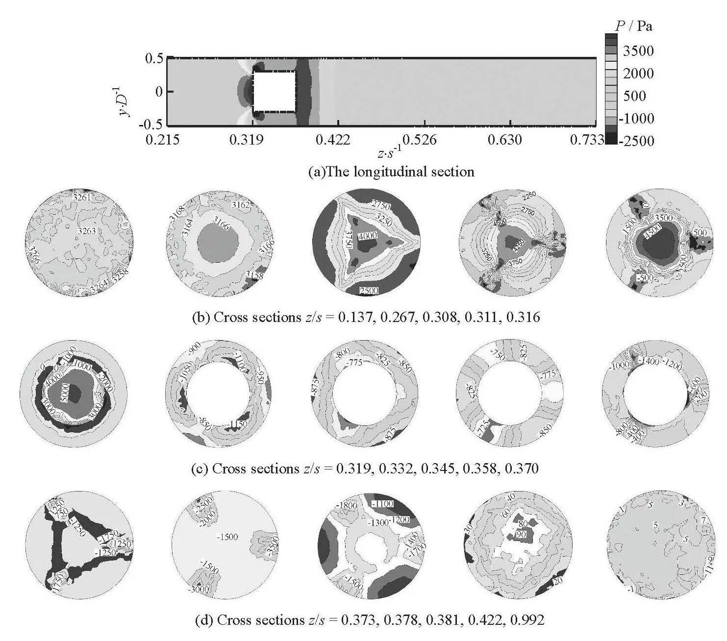
Fig.10 Pressure contours in several sections at Case 1
In the following segment of the annulus, the flow is restricted forward. So, the streamlines go from the pipe wall towards the inside in the following three sections, as is opposite to the case of the front neighboring region. In the three sections, the streamlines inz/s=0.358 show the most obvious bending. There are several intersection points in sectionz/s=0.370.Most streamlines start from one point to the neighboring one without pointing to the wall boundary. That is because the fluid flows out of the annulus and turns to fully fill the entire pipe cross section in this section.Meanwhile, the chocked flow effect of these downstream attaching cylinders spreads up there. The combined effect of the formers in the outlet section of the annulus leads to a new appearance.
In sectionz/s=0.373, the outer streamlines are the same as in sectionz/s=0.370 and a divergence from the circle center appears, divided by the three connection sheets. The divergence sustains in the next sectionz/s=0.378 and the outer streamlines remain similar with those in sectionz/s=0.358. According to analyses of Figs.6(a) and 6(b), the former sectionsz/s=0.373 and 0.378 are in the range of the reversing zone behind the cylindrical body. So the patterns of cross sectional streamlines there are rich in their variety. They are in the part near the cylindrical body in the reversing range. The stream flows from the center point to the surrounding area. Thus the divergence appears. Sectionz/s=0.422 is not in the reversing zone but in the tongue zone (Fig.5(a)), where the streamlines start from the pipe wall to converge at an inner position. In the following section (z/s=0.630),the range of the inward convergence increases. Near the pipe outlet (z/s=0.992) and in the outlet section (z/s=1), which are not in the tongue zone, the convergences appear as bending lines deviating from the section center. That is because the stream behavior in the pipe turns to be simple. The flow conduct in the cross sections decreases and the range of zero velocity increases in the appearance of lines. Based on above discussions, the flow patterns in the cross sections can be understood to a certain degree. Similar changes ofcross sectional streamlines along the pipe flow exist in other cases, which will not be discussed in detail in this paper.
3.4 Sectional pressure characteristics
The pressure distributions in the longitudinal section (x/D=0) and the feature cross sections in Case 1 are shown in Fig.10. From the longitudinal distribution (in Fig.10(a)), it can be seen that a high pressure zone exists in front of the main cylinder due to the low velocity. In front of the high pressure zone, a full segment with lower pressure is formed. Above and below the cylinder, the low pressure regions caused by the high velocity annulus zone are gradually disappearing.And the lowest value is found at the edge of the upstream end of the main cylinder. Outside of the annulus space, the pressure gradually rises up along the pipe filling a full section. To discuss the cross sectional pressure distribution, several feature cross sections in segments in front of the body (Fig.10(b)), in the annulus (Fig.10(c)) and behind the body (Fig.10(d)) are selected. In each cross section, the values are given instead of using scales. Sectionz/s=0.137 is chosen to analyze the sectional pressure distribution away from the cylindrical body in the upstream region. The pressure difference between the maximum and the minimum values is rather small and the areas with different values scatter in the section, outside of the affected range in front of the cylindrical body. As the fluid flows forward to be impacted by the cylindrical body, the pressure difference between the highest and the lowest values in sectionz/s=0.267 decreases and a high circle zone appears around the center. In the chocked flow region in front of the circular end of the main cylinder, the circle high pressure area is formed. Regions with different values disorderly scatter in the outside of the circular zone. In the range of the high pressure zone in front of the body (described in Fig.10(a)), the inside pressure turns to be triangularly distributed with the positions of the attaching cylinders as the apices in sectionz/s=0.308. That is because this section is in the affected range of the upstream attaching cylinders. And in this section, the range of pressure values increases to a larger value. The pressure distributions in the following two sections ofz/s=0.311 and 0.316 follow a generally similar pattern as the former one. Due to the altered scales to give good descriptions, the figures show a more detailed appearance. Meanwhile, negative pressures appear behind the attaching cylinders in sectionz/s=0.316,which is located at the back edge of the attaching cylinders.
Sectionsz/s=0.319, 0.332, 0.345, 0.358 and 0.370 are in the annulus space. In these sections, the absolute value of the negative pressure is at a higher level than that in sectionz/s=0.316, which is because the velocity in the annulus rises up and while the pressure goes down. With the changed positions of these cross sections, the pressure distributions are in different patterns exhibited in Fig.10(c).
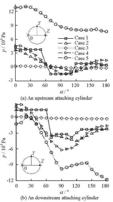
Fig.11 Circumferential pressure distributions on attaching cylinders surfaces
Outside of the annulus, a zone of higher pressure than the surrounding values is formed owing to the low velocity zone in the core region of each cross section behind the main cylinder in Fig.10(d). In section/=0.373zs, a feature triangular lower pressure region around the core zone appears and the highest values are taken at the three apices. That is because in the core zone the velocity is the lowest and the pressure there is higher than that in the surrounding area.Meanwhile, this section locates in the chocked flow region behind the downstream attaching cylinders.Then three apices with high pressure are formed. In the next section, the values in the three apices locations become the lowest and the same phenomenon appears in section /=0.381zs. The three apices are located in the wake region of these downstream attaching cylinders, where the velocity is high and the pressure is low. Due to the refined scales, the highest regions between two neighboring apex locations and the triangular zone are displayed in more detail. As the fluid flows forward, the triangular zone disappears gradually and it is found that a higher pressure is in the inside and a lower pressure is in the outside in section /=0.422zs. In section /=0.992zsnear theoutlet, the value range reduces and the plaque areas with different pressures scatter disorderly. Based on the above pressure discussions in the feature cross sections, the evolution of the characteristics of the cross sectional pressure is generally illustrated.
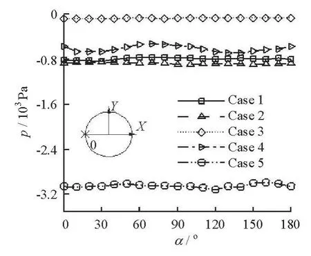
Fig.12 Circumferential pressure distributions on the main cylinder surface
3.5 Circumferential pressure distributions on cylindrical body surfaces
In Fig.11, the circumferential pressures on a pair of attaching cylinders surfaces are analyzed with coordinates and starting points labeled in the figures, in whichαmeans Angle on the horizontal axis. The circle centers of the researched pressure circumferences are located on the intermediated ring in the annulus. Figure 11(a) shows the circumferential pressures on the upstream attaching cylinder in all cases. The researched circumferential pressure in Case 5 is at the highest level, which is because the discussed location is the nearest to the core of the low velocity zone in front of the main cylinder due to the largest main cylinder diameter in Cases 1, 2, 4 and 5. The velocity decreases in the largest range and the pressure is at the highest level correspondingly. On the other hand, on the downstream attaching cylinder the pressure is the lowest (see Fig.11(b)), which means that the largest pressure drop between the two cylinders exists in this case. Owing to the disturbed flow upstream, the fluctuations appear in the pressure distribution on the downstream attaching cylinder. In Case 3, the pressures on the surfaces of the cylinders both upstream and downstream are in flat distributions, meaning that small difference exists among different directions with respect to the flow. That is due to the fact that the investigated position in this case is far from the pipe wall and the flow velocity is the lowest among all cases.The two combined effects lead to the flat distribution.The other three cases see analogous pressure distributions on the surfaces of the pair of attaching cylinders.The three cases have similar fluctuation trends except with some sharp jumps and small value differences,implying that the length of the main cylinder and the size of the attaching cylinder have very slight impacts on the investigated pressure as compared with other factors of the pipe size and the main cylinder diameter.
Figure 12 shows the surface pressures, at the middle position along the length of the main cylinder,from the starting point “0”, as is denoted in the coordinate. All pressure curves have small fluctuations around the half circumference. Among these pressure curves, the pressure values in Case 5 are obviously smaller than others, which are caused by the highest velocities in the thinnest annulus due to the enlarged diameter of the main cylinder. Among all comparisons between Case 1 and others, the smallest difference is between Case 1 and Case 2, meaning that the length of the main cylinder has only a slight impact on the discussed circumferential pressure distribution on the main cylinder. In Case 4, affected by the enlarged attaching cylinder diameter, the pressure values increase slightly and the curve has a most obvious fluctuation,meaning that these upstream attaching cylinders have impacts on the annulus and the impacts can not be eliminated by the redistribution flow in the half way of the annulus. The pressure in Case 3 with the largest pipe diameter is at the highest level. In this case, the width of the annulus is larger than others and the average velocity is the smallest under the same Reynolds number condition. Thus, the pressure level on the main cylinder surface is the highest among all cases.In all cases, the negative pressure on all main cylinder surfaces may lead to cavitation, which is not conducive to the cylindrical body. The above analyses show that the enlarged pipe diameter is an optional parameter to reduce the negative pressure under a fixed Reynolds number condition.

Table 2 System drag coefficient targets of each type of cylindrical body in five cases
3.6 Drag force coefficient
The system drag coefficient target is defined as
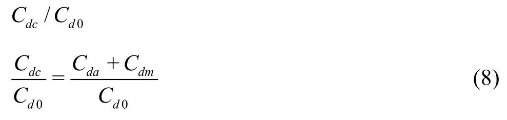
Here the system means the cylindrical body consisting of the main cylinder and the attaching cylinders.,,andare the drag coefficients of thesystem, the main cylinder in the system, the attaching cylinders in the system and the main cylinder only in the pipe.
The system drag coefficient target in each compared case is given in Table 2. It is shown that the system drag coefficient target in Case 1 (the original case)is 1.33, which means that a drag increasing effect is a result of attaching cylinders arranged on the main cylinder in the present wall-bounded calculation domain of the pipe. The system drag coefficient target in Case 5 is obviously higher than others. The reason is that the diameter of the main cylinder is increased to 4d/3 (as shown in Table 1) and the upstream end face is enlarged to generate forces from the pressure difference. Meanwhile, the drag force is generated by the forces from pressure difference and friction. As a result of the enlarged diameter of the main cylinder, the drag force on the body increases andrises up in a large margin. The target value in Case 3 is obviously lower than others owing to the enlarged pipe diameter (2D). As a consequence of the pipe diameter increase, the flow velocity in the inlet decreases at a fixed Reynolds number. Thus, the forces from pressure difference and friction are decreased and then the system drag coefficient target is reduced. Unlike the above two comparing cases, the target value in Case 2 is slightly higher than that in Case 1. And Case 4 gives a little higher difference value. The phenomenon implies that the enlarged length of the cylindrical body hardly has any influence on the drag force and the impact due to the enlarged diameter of the attaching cylinders is at a low level.
4. Conclusions
Numerical simulations of the concentric annulus flow in the limited pipe domain show characteristics of the complex flow in detail. Some main conclusions are summarized as follows:
(1) In all investigated computational cases, the velocity distributions see sharp fluctuations along the pipe axis behind the cylindrical body, as the tongue wake zones in the longitudinal sections with nested velocities higher than those in the surrounding areas.A pair of reversing zones appears in each tongue region, which is illustrated by the velocity vectors and streamlines in the longitudinal sections. Besides, the annulus is an area with high velocity due to the decreased cross area for the flow. Behind the attaching cylinders both upstream and downstream, there is no vortex shedding formed.
(2) For the velocities in three dimensions, the axial velocity is the main velocity in the pipe flow. At the edges of the main cylinder and the attaching cylinders, the velocities in the other two directions are higher than those in other spaces in the pipe due to the flow steering. Among various effects on the axial velocity distribution, the length of the main cylinder has not effect on the distribution trend. The enlarged attaching cylinder diameter reduces the wake core with the lowest velocity and the enlarged main cylinder diameter improves the lowest region and the wake width. The streamline patterns in the cross sections along the pipe experience several feature developing stages, illustrating the flow behaviors in the cross sections. There are many intersections in these sections,which mean that the total velocity (combined byX-velocity andY-velocity) of zero value exists in these sections.
(3) The pressure in the annulus is the lowest, as compared with the two sides outside of the annulus in the pipe, due to the highest velocity there. With changes of the distance from the discussed cross section to the cylindrical body, the sectional pressure distributions turn to be in different appearances. Among these affecting factors, the length of the main cylinder and the diameter of the attaching cylinders have weak impacts on the pressure distributions on the attaching cylinder surfaces. But the other two factors lead to obvious changes of the pressure values and the distribution tendencies in the discussed characteristics. Similar analyses of these factors are made from the circumferential pressure distributions on the main cylinder surface.
(4) The analysis on the defined system drag coefficient target shows that the enlarged pipe diameter decreases the drag coefficient and the enlarged diameter of the main cylinder increases the value greatly.The target values for the other two changed factors rise up slightly.
[1] FARRANT T., TAN M. and PRICE W. A cell boundary element method applied to laminar vortex shedding from circular cylinders[J]. Computers and Fluids,2001, 30(2): 211-236.
[2] BEHZAD A. A., ABOLFAZL A. K. Flow field around single and tandem piers[J]. Flow, Turbulence and Combustion, 2013, 90(3): 471-490.
[3] KANG S. Characteristics of flow over two circular cylinders in a side-by-side arrangement at low Reynolds numbers[J]. Physics of Fluids, 2003, 15(9): 2486-2498.
[4] HARICHANDAN A. B., ROY A. Numerical investigation of low Reynolds number flow past two and three circular cylinders using unstructured grid CFR scheme[J]. International Journal of heat and fluid flow,2010, 31(2): 154-171.
[5] ZHANG P., WANG J. and HUANG L. Numerical simulation of flow around cylinder with an upstream rod in tandem at low Reynolds numbers[J]. Applied Ocean Research, 2006, 28(3): 183-192.
[6] WANG J., ZHANG P. and LU S. et al. Drag reduction of a circular cylinder using an upstream rod[J]. Flow,Turbulence and Combustion, 2006, 76(1): 83-101.
[7] BAO Y., ZHOU D. and HUANG C. Numerical simulation of flow over three circular cylinders in equilateral arrangements at low Reynolds number by a secondorder characteristic-based split finite element method[J].Computers and Fluids, 2010, 39(5): 882-899.
[8] FARRANT T., TAN M. and PRICE W. A cell boundary element method applied to laminar vortex-shedding from arrays of cylinders in various arrangements[J].Journal of Fluids and Structures, 2000, 14(3): 375-402.
[9] LAM K., GONG W. and SO R. Numerical simulation of cross-flow around four cylinders in an in-line square configuration[J]. Journal of Fluids and Structures,2008, 24(1): 34-57.
[10] LAM K., ZOU L. Experimental study and large eddy simulation for the turbulent flow around four cylinders in an in-line square configuration[J]. International Journal of Heat and Fluid Flow, 2009, 30(2): 276-285.
[11] BAO Y., WU Q. and ZHOU D. Numerical investigation of flow around an inline square cylinder array with different spacing ratios[J]. Computers and Fluids, 2012,55: 118-131.
[12] YANG An-mei, LV Lin and DONG Guo-hai et al. Numerical simulation of flow around affiliated multi-circular cylinder[J]. China offshore platform, 2009, 24(6):7-12(in Chinese).
[13] HUANG Z., OLSON J. and KEREKES R. et al. Numerical simulation of the flow around rows of cylinders[J]. Computers and Fluids, 2006, 35(5): 485-491.
[14] FEDOSOV D. A., PIVKIN I. V. and KARNIADAKIS G. E. Velocity limit in DPD simulations of wall-bounded flows[J]. Journal of Computational Physics, 2008,227(4): 2540-2559.
[15] MARUSIC I., MCKEON B. and MONKEWITZ P. et al.Wall-bounded turbulent flows at high Reynolds numbers: Recent advances and key issues[J]. Physics of Fluids, 2010, 22(6): 065103.
[16] WEI T., FIFE P. and KLEWICKI J. et al. Properties of the mean momentum balance in turbulent boundary layer, pipe and channel flows[J]. Journal of Fluid Mechanics, 2005, 522: 303-327.
[17] WOSNIK M., CASTILLO L. and GEORGE W. K. A theory for turbulent pipe and channel flows[J]. Journal of Fluid Mechanics, 2000, 421:115-145.
[18] BARENBLATT G. L. Scaling laws for fully developed turbulent shear flows. Part 1. Basic hypotheses and analysis[J]. Journal of Fluid Mechanics, 1993, 248: 513-520.
[19] RODRIGUEZ-CORREDOR F. E., BIZHANI M. and ASHRAFUZZAMAN M. et al. An experimental investigation of turbulent water flow in concentric annulus using particle image velocimetry technique[J]. Jounal of Fluids Engineering, 2014, 136(5): 051203.
[20] ZHANG Xue-lan, SUN Xi-huan and LI Yong-ye. 3-D numerical investigation of the wall-bounded concentric annulus flow around a cylindrical body with a special array of cylinders[J]. Journal of Hydrodynamics,2015, 27(1): 120-130.
猜你喜歡
今日農(nóng)業(yè)(2022年4期)2022-11-16 19:42:02
江蘇安全生產(chǎn)(2021年8期)2021-11-05 08:14:46
公民與法治(2020年10期)2020-07-25 01:41:28
國防(2019年6期)2019-07-20 06:19:44
幽默大師(漫話國學(xué))(2019年6期)2019-06-13 02:51:52
領(lǐng)導(dǎo)決策信息(2017年17期)2017-06-21 09:51:21
僑園(2016年8期)2017-01-15 13:57:32
新聞傳播(2015年4期)2015-07-18 11:11:29
學(xué)習(xí)月刊(2015年22期)2015-07-09 03:40:32
發(fā)明與創(chuàng)新(2015年37期)2015-02-27 10:40:32

- 水動力學(xué)研究與進(jìn)展 B輯的其它文章
- Erratum to “Estimation of drag forces caused by natural woody vegetation of different scales”
- The effect of a curved bed on the discharge equation in a spillway with a breast wall*
- Irreversibility analysis of unsteady couette flow with variable viscosity*
- Three-dimensional simulation for problem of penetrative convection near the maximum density*
- Effect of vegetation on flow structure and dispersion in strongly curved channels*
- Thermodynamic analysis for a third grade fluid through a vertical channel with internal heat generation*