
Experimental and Numerical Study on Heat Transfer Enhancement of a Rectangular Channel with Discontinuous Crossed Ribs and Grooves*
2012-10-31 03:34:54TANGXinyi唐新宜andZHUDongsheng朱冬生
TANG Xinyi (唐新宜) and ZHU Dongsheng (朱冬生)**
Key Laboratory of Enhanced Heat Transfer and Energy Conservation of the Ministry of Education, South China University of Technology, Guangzhou 510640, China
Experimental and Numerical Study on Heat Transfer Enhancement of a Rectangular Channel with Discontinuous Crossed Ribs and Grooves*
TANG Xinyi (唐新宜) and ZHU Dongsheng (朱冬生)**
Key Laboratory of Enhanced Heat Transfer and Energy Conservation of the Ministry of Education, South China University of Technology, Guangzhou 510640, China
Experimental and numerical investigations have been conducted to study turbulent flow of water and heat transfer characteristics in a rectangular channel with discontinuous crossed ribs and grooves. The tests investigated the overall heat transfer performance and friction factor in ribbed and ribbed-grooved channels with rib angle of 30°. The experimental results show that the overall thermo-hydraulic performance for ribbed-grooved channel is increased by 10%-13.6% when compared to ribbed channel. The investigation on the effects of different rib angles and rib pitches on heat transfer characteristics and friction factor in ribbed-grooved channel was carried out using Fluent with SST (shear-stress transport) k-ω turbulence model. The numerical results indicate that the case for rib angle of 45° shows the best overall thermo-hydraulic performance, about 18%-36% higher than the case for rib angle of 0°. In addition, the flow patterns and local heat transfer characteristics for ribbed and ribbed-grooved channels based on the numerical simulation were also analyzed to reveal the mechanism of heat transfer enhancement.
heat transfer enhancement, rib, groove, rectangular channel, turbulent flow
1 INTRODUCTION
The increasing necessity for saving energy and material caused by the world resource shortage and environmental concerns has prompted to develop more effective heat transfer equipment [1]. The techniques of heat transfer augmentation attract the interests of scientists [2]. Ribs are often used to enhance forced convective heat transfer between the wall and fluid because they cause flow separation and reattachment, consequently resulting in destroying the laminar sublayer.
In the past, investigations on turbulent flow and heat transfer enhancement in ducts or channels with rib, groove or rib-groove turbulators have been carried out extensively. Hu and Shen [3] measured detailed distributions of internal heat transfer coefficients in a convergent cooling passage with a staggered array of 45° discrete ribs, and combination of ribs with grooves. The area-averaged enhancement factors of 3-4 for discrete ribs and of 2.5-3.2 for the combination of discrete ribs with grooves have been obtained.Eiamsa-ard and Promvonge [4] performed experimental work on the turbulent forced convection heat transfer and friction characteristics in a rectangular duct with three types of rib-grooved turbulators(rectangular-rib and triangular-groove, triangular-rib and rectangular-groove and triangular-rib with triangular-groove). They found that the use of turbulators at lower Reynolds number (Re) gives higher enhancement index and in comparison with the smooth duct,all rib-groove arrangements significantly enhance the heat transfer up to 80%, 60%, and 46%, respectively.The friction factors are approximately 6.9, 5.5 and 4.8 times above the smooth duct, respectively. Eiamsa-ard and Promvonge [5] reported the heat transfer enhancement in a heat exchanger with delta-wing tape inserted.Kaewkohkiat et al. [6] experimentally studied on the heat transfer and friction characteristics in a rectangular channel with rib-groove turbulators and reported that both Nusselt number and friction factor increase with decreasing pitch ratio. Bilen et al. [7] experimentally studied heat transfer and friction characteristics of a fully developed turbulent air flow in different grooved tubes (circular, trapezoidal and rectangular) and reported that heat transfer enhancement is up to 63% for circular groove, 58% for trapezoidal groove and 47% for rectangular groove, in comparison with the smooth tube at the highest Reynolds number of 38000. Layek et al. [8,9] experimented on Nusselt number and friction factor in a chamfered ribbed duct with V-groove having chamfer angles of 5°, 12°, 15°, 18°, 22°and 30°. They found that the performance parameter increases with increase in Reynolds number. Overall, the mechanism of heat transfer enhancement by the ribs is based on the flow separation, reattachment and secondary flow.
Recently, in order to reduce the flow resistance in the channel with ribs, numerous investigations on the flow and heat transfer for the discrete inclined ribs have been carried out [10, 11]. In their work, the inclined discrete ribs have been used as longitudinal vortices generator and the heat transfer rate is increased by 150%-300% over the plain duct with less pressure loss compared with transversal ribs. Inclined discrete ribs can generate longitudinal vortices and give less blockage of the channel, thus increasing the heat transfer rate of the channel with less pressure drop. Use of the artificial grooves is widely used in modern heat exchangers, because they are very effectivein heat transfer augmentation. In this work, the combination of crossed and discontinuous ribs-grooves array was used to enhance heat transfer with less pressure loss and the better thermal performance is expected.The analysis pays particular attention to the effects of geometric parameters and complex flow structures on heat transfer enhancement based on the numerical simulation.
2 EXPERIMENTAL MODEL AND PROCEDURE
A ribbed channel without grooves and a ribbed-grooved channel with rib angle of 30°and rib pitch of 15 mm are tested and compared in the experimental work. For the ribbed-grooved channel,eight ribs and three grooves in rows are mounted on the flat plate, and grooves are set perpendicular to ribs,while only eight ribs are mounted on the plate in the ribbed channel. The positions of ribs and grooves are also shown in Fig. 1. The geometric dimensions of ribbed channel and ribbed-grooved channel are listed in Table 1 and Fig. 2. The parameters of ribbed channel without grooves [Fig. 2 (a)] are similar to the ribbed-grooved channel [Fig. 2 (b)]. In the rectangular channel, the ribs and grooves [Fig. 1 (b)] are oblique to the main flow direction. The physical model of rib used in this work is shown in Fig. 1 (a). The same sizes of the 3D ribs and grooves are used. The geometrical parameters for the rectangular channel with discontinuous ribs-grooves are the rib height, e, rib length, l, rib width, w, rib longitudinal pitch, p, rib transverse pitch, c, and slope angle, α, and inclined angle for side wall of the rib, β. The cases with different geometrical parameters are listed in Table 2.
The experimental system shown in Fig. 3 consists of a cold water tank, settling chamber, test section,sensors and data collectors. The test section is a rectangular duct with the cross section of 41 mm×20 mm and a length of 600 mm. The ribs and grooves were made by pressing on a sheet of stainless steel plate.The ribbed-grooved plate with 1 mm in thickness was manufactured by punch die forming technology with a machining precision of ±0.1 mm. Before the test section,there is a 300 mm-long entrance section of the channel.A flow straightener was installed in the settling chamber to reduce the vortices and align flows. The flow rate in the rectangular duct was measured by volumetric flow meter with an accuracy of 3% and controlled by a valve installed on the pipeline. The pressure drop was measured by a differential pressure transducer with an accuracy o f 1 Pa and the full scale range of 1000 Pa. Both the inlet and outlet temperatures of the water were measured by using four calibrated chromel-alumel Type-K thermocouples with accuracy of ±0.1 °C. Fifteen thermocouples were attached to the bottom wall of test section. The data were collected by data acquisition system (34970A, Agilent).Temperatures measured for 10 s intervals were collected, stored in a PC and then analyzed. In order to obtain constant heat flux, an electrical heating plate was tightly attached to the bottom and upper surface of the test section by using the silicone greases. The test plate and the heating plate were pressed tightly on the test section. The heating plate with 1.5 mm in thickness was connected with a DC power supply and power output controller. A digital multimeter with accuracy of ±1% for voltage and ±1% for resistance was utilized. The side surfaces were adiabatic. The test section was wrapped with a layer of insulated material made by plastic foam.

Table 1 Summary of geometrical parameters of rectangular channel with discontinuous crossed ribs-grooves

Table 2 Geometrical parameters for ribs-grooves cases

Figure 1 3-D views of rectangular channel with ribs and grooves

Figure 2 Structure and layout of the rectangular channel with discontinuous crossed ribs and grooves

Figure 3 Experimental system 1—flow straightener; 2—settling chamber; 3—water pump; 4—valve; 5—cold water tank; 6—cooling system; 7—volumetricflow meter; 8—data acquisition system; 9—computer system; 10—heat exchanger; 11—differential pressure transducer; 12—thermocouple
For each test run, steady state conditions were assured by checking both temperature and differential pressure readings. The outflow water was cooled by a cooling system. The inlet water temperature was maintained at 20 °C by a temperature controller. All temperatures, volumetric flow rate and pressure drop were collected after conditions had been steady.
3 MATHEMATICAL DESCRIPTION
The numerical simulations were performed using the CFD software package Fluent 6.3. The general forms of the governing equations are:
continuity equation:
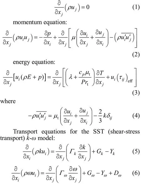
where Gkrepresents the generation of turbulent kinetic energy due to the mean velocity gradients, Gωrepresents the generation of ω, Ykand Yωrepresent the dissipation of k and ω due to turbulence, and Dωrepresents the cross-diffusion term.
4 DATA REDUCTION
The net heat transfer rate from the wall is calculated as

where Qlossis the rate of heat loss, G is the mass flow rate of water through the test section and electrical power Qeis calculated as

From the calculation of the heat balance at the steady state flow condition, Qlossis found to be about 7%-12% of the input electrical power. With the rise of Reynolds number, Qlossis decreased because the thermal resistances in convective heat transfer are reduced.Based on the thermal balance calculation, it is found that Qlosscan’t be negligible.
The average Nusselt number Nuavefor the channel in the experiment is defined based on the net heat transfer rate Qnetas

Here A is the heating area of test plate, Dhis the hydraulic diameter of channel, which is calculated from Dh4Ac/P, where Acis the cross-sectional area of the flow and P is the wetted perimeter. λ is the fluid thermal conductivity, Tbis bulk mean temperature of the fluid, which is calculated as


The overall average Nusselt number, friction factor and Reynolds number are

where u is the bulk mean channel velocity over the channel cross section.
In order to compare the heat transfer performance of different channel at the same pumping power, the thermal enhancement factor (η) used to evaluate the overall performances is defined as [12]:

where0Nu and0f stand for Nusselt number and friction factor for the smooth channel, respectively.
For the experimental results, the Nusselt number and friction factor correlations for the smooth channel are used as a benchmark to show the heat transfer enhancement factor and friction factor ratio of the ribbed and ribbed-grooved channels. The Nusselt number and friction factor for the smooth channel are calculated using the correlations proposed by Gnielinski [13],Petukhov and Hartnett [14], respectively:Gnielinski correlation

5 NUMERICAL SIMULATION METHOD AND VALIDATION
The grid with a million hexahedral elements is divided into three parts in the computational domain—the near wall region, the extended region and the ribbedgrooved region. Mesh density in the vicinity of the ribbed-grooved wall and bottom wall are fine to ensure the accuracy of the numerical results, and the meshing follows a uniform distribution in the inlet and outlet parts. To ensure that the fully-developed flow is formed at the entrance of ribbed-grooved channel region and reversed flow does not appear at the outlet, upstream and downstream region are extended 3 times of channel height and 6 times of channel height, respectively.
Figure 1 (b) shows a schematic of the boundary for the computation. The bottom wall was heated with isothermal wall temperature (Tw=333 K), and side walls of the channel were set as adiabatic conditions.To reduce the computation effort the channel geometry was reduced and only half of the segment was investigated. The top wall of channel was set as a symmetry condition. All of the simulations were carried out with Reynolds number based on the hydraulic diameter (Dh), ranging from 5354 to 16063. The details of boundary conditions in the computation are listed in Table 3. The boundary conditions in the computation are identical to the experiments except thermal condition on the bottom wall. For turbulent flow with Pr > 0.7, the difference of the Nusselt number between the constant wall heat flux condition and isothermal wall temperature can be negligible due to the intense mixing between the fluids [15]. The SIMPLE algorithm was used for the velocity-pressure coupling. The second order upwind scheme was used for the discretization of the convective terms. The shear-stress transport (SST) k-ω model was adopted as turbulence model. This model used a low-Reynolds number approach for the description of the flow in the region near the wall, which allowed the resolving of details in the viscous sublayer by applying very fine mesh near the walls. Three dimensional and incompressible Navier-Stokes equations were solved by the commercial software Fluent 6.3. The convergence criteria for the velocity, k and ω were less than 10?5with being less than 10?8for energy equation.
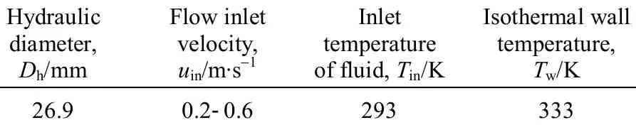
Table 3 Boundary condition of the computation
6 RESULTS AND DISCUSSION
6.1 Experimental uncertainty estimate and validation
The uncertainty estimate was conducted with the method proposed by Kline and McClintock [16]. The maximum uncertainties for Nu and f were ±10.8% and±8.2% respectively, whereas the uncertainty in temperature measurement on the plate wall was about±3%. The experimental validity was performed by comparing with the correlations on friction factor and Nusselt number for a smooth duct. Fig. 4 shows the variation of f and Nu with Re between experimental data and correlation in the smooth duct. The Nusselt number for the smooth duct is found to agree with Eq.(16) within less than 10% and the friction factor agrees well with Eq. (18) within less than 8% for the Reynolds number range of 5354-16063. Therefore,the pressure drop and heat transfer measurements in the experiment were reliable.
Grid independence test at the Re=16063 for Case 2 was conducted by varying the number of meshes. The results of grid independence test are shown in Table 4. The relative difference of the average Nusselt number between the two maximum grids is less than 1%. Therefore, the grid with 964573 elements was used for the simulations, considering the compromise of computational time and accuracy.

Table 4 Grid independency test at Re=16063 for Case 2
6.2 Comparison of experimental and numerical results
The numerical results of ribbed and ribbedgrooved channel for the case of α =30°, p 15 mm were compared with the experimental data to validate the computational model. Fig. 4 shows that the numerical results agree well with the experimental results for both the Nu and friction factor with relative differences less than 10% and 12% respectively. The relative differences may be caused by several reasons as follows: (1) the assumption of turbulent model is different from the real flow; (2) the differences between experimental model and numerical model; (3)the relative errors in experimental measurement; (4)differences of inlet turbulent intensity between experiment and simulation. Therefore, the computational model is reliable.
In terms of experimental results, it is observed from Fig. 4 that the Nusselt number for ribbed-grooved channel is enhanced by about 16.2%-21.1%, and the friction factor is increased by about 17%-20.9%,compared with ribbed channel. The reason of heat transfer enhancement in the ribbed-grooved channel is that the presence of grooves distorts the flow field when compared to ribbed channel. The increase in flow resistance is induced by the flow separation and additional vortices in the flow field.
The variation of the Nusselt number ratio (Nu/Nu0)and friction factor ratio (f/f0) obtained from the experiments for ribbed channel and ribbed-grooved channel is presented in Fig. 5 (a). It is seen from the figure that the Nusselt number ratio tends to decrease with the rise of the Reynolds number for all channels.On the contrary, the friction factor ratio increases with the increasing Reynolds number. The Nusselt number ratios are found to be about 2.3-2.9 and 2.8-3.5 for ribbed channel and ribbed-grooved channel, respectively. On the other hand, the friction factor ratios for ribbed-grooved channel are in the range of 4.0-4.6,higher than that for ribbed channel.
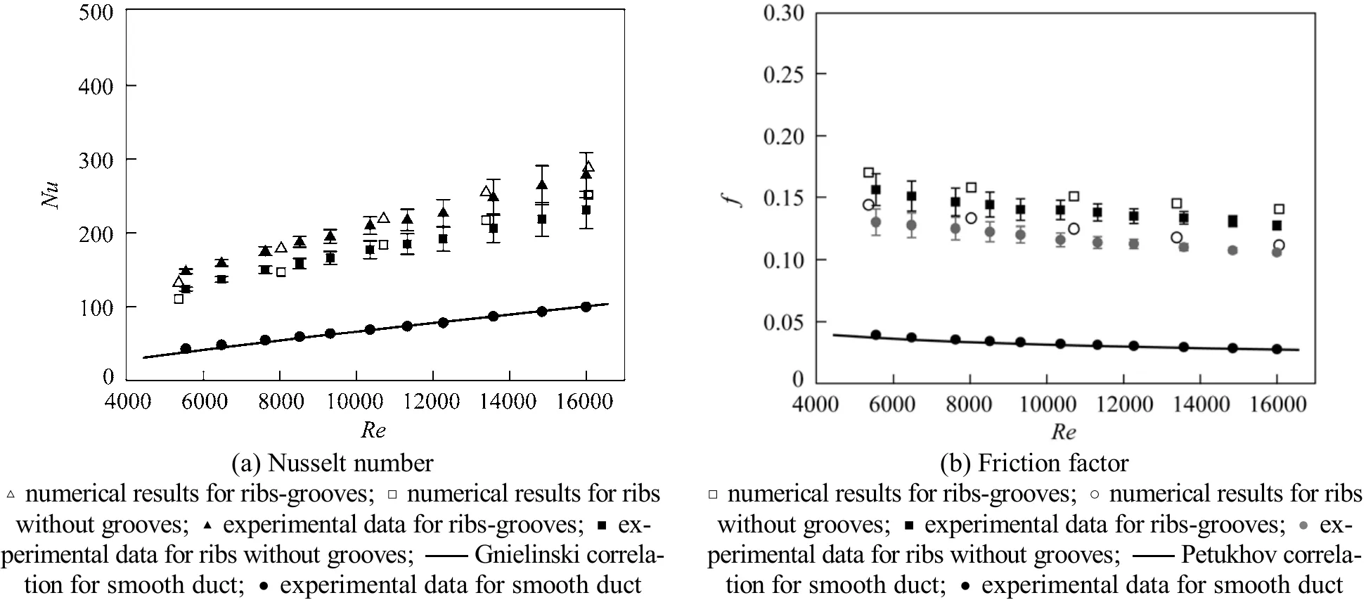
Figure 4 Comparison of simulated results, experimental data and correlation

Figure 5 Overall performance ratios for ribbed and ribbed-grooved channel in the experiment
Figure 5 (b) shows the overall thermal performance factors for ribbed and ribbed-grooved channel obtained from the experiments. It is observed that the thermal performance factors for ribbed channel and ribbed-grooved channel are above unity and their values are in a range of 1.48-1.95 and 1.67-2.19, respectively. Compared with ribbed channel, the overall thermal performance of ribbed-grooved channel is increased by about 10%-13.6%.
6.3 Numerical simulations for different slope angles and spacings of ribs-grooves
Figures 6-8 show the variation of the three different thermo-hydraulic performance ratios such as f/f0,Nu/Nu0and η, where the subscript (0) in the definitions of each performance ratio denotes the smooth channel without the ribs and grooves.

Figure 6 Variations of the Nusselt number ratios and friction factor ratios as a function of slope angle■ α =30° (Case 1); ● α =45° (Case 2); ▲ α =60° (Case 3);▼ α =0° (Case 4)
Figure 6 shows the Nusselt number and friction factor ratios for Cases 1, 2, 3 and 4, with slope angle from 0°-60° and a constant pitch d=15 mm. Case 1 shows the maximum value of Nusselt number ratio,probably because the flow is oriented by the ribs and more fluids travel to the grooves, inducing intense flow separation, flow attachment and flow ejection.The helical motion, induced by the inclined discrete ribs, is formed in the flow field. Therefore, the fluids near the ribs are wrapped into the mainstream and the fluid mixing is intensified, thus enhancing the heat transfer. With increasing slope angle, the heat transfer near the ribs is enhanced because the secondary flows induced by the rib-directed flow are intensified. The increasing slope angle of rib implies that the windward surface is enlarged and the Nusselt number on the windward surface is increased due to the mechanism of flow impingement. For Case 4 of α 0°, the Nusselt number is lower than other cases probably due to weaker secondary flow and shrunken windward surface of ribs.
Figure 7 shows the variation of Nusselt number ratios and friction factor ratios with Reynolds number for different rib pitches. With the variations of rib pitches, the degree of heat transfer enhancement Nu/Nu0is between 2.8-3.7, while the friction factor ratio varies from 4.4-5.2. The reduction of rib pitches increases the turbulent mixing in the duct, resulting in increasing the heat transfer rates.
The variations of overall thermo-hydraulic performance ratios are shown in Fig. 8. For the constant rib pitches, Case 2 shows the best overall performance,about 18%-36% higher than Case 4. For constant slope angle, the overall performance ratio is maximized at Case 5 among the present three cases with different rib pitches, and the increment is approximately 7.3%, compared to Case 6 with largest rib pitches.
Figure 7 Variations of the Nusselt number ratios and friction factor ratios as a function of rib pitch p/mm: ■ 15 (Case 2); ● 13 (Case 5); ▲ 17 (Case 6)
Figure 9 shows that the overall thermal-hydraulic performance ratio for Case 2 is about 1.7-2 times that for 90° ribs at Reynolds numbers between 5500 and 14000. Furthermore, the overall thermal-hydraulic performance ratio for Case 2 is improved by about 10.1%-19.4% compared with V-shape ribs, which indicates that the combination of ribs and grooves can improve the overall thermal-hydraulic performance ratio in the rectangular channel. The data of overall thermal-hydraulic performance ratio for the V-shape ribs and 90° ribs are given by Peng et al [17].
6.4 Flow field and heat transfer characteristics from numerical results
In this section, the numerical results of the flow pattern and the local heat transfer characteristics in the ribbed channel and ribbed-grooved channel are based on the Case 1 at Re 8031, α =30° and p=15 mm.

Figure 8 Variations of the different thermo-hydraulic performance ratios as function of different parameters

Figure 9 Comparison of overall thermal-hydraulic performance ratio for different ribs▲ V-shape ribs [17]; ● 90° ribs [17]; □ present work (Case 2)

Figure 10 Streamline in the ribbed-grooved channel (Case 1, Re 8031)
Figure 10 shows the streamlines near the ribsgrooves for Case 1 at Re 8031. The flow-recirculating regions widely generated inside the grooves induce the helical motion. The tornado-like structures with two vortices are transformed into jet-vortex structures.The helical streamlines show that the vortices move along the side wall of the rib and interact with each other behind the ribs due to the rib-directed flow. It is noted that the coming vortex core passes around the trailing edge of the previous rib, and then merges into the new vortex. The recirculation, flow attachment and secondary flow appear inside the grooves. The flow ejection at the rear edge of the grooves washes the wall continuously, enhancing the heat transfer near this region. Mixing enhancement induced by the vortices around the ribs-grooves intensifies the velocity fluctuation in the flow field.
Figure 11 shows the secondary flow in the downstream cross section of ribbed-grooved channel. It is found that the secondary flow velocities are quite large at the trailing edge of ribs near the bottom wall.Therefore, the fluid washes upon the bottom wall and heat transfer rate is high in this region. Two primary longitudinal vortices with two secondary vortices appear on the cross section downstream.
Figure 12 shows the turbulent intensity (Tu) distribution on the cross section downstream for Case 1 at Re=8031. The region of high Tuappears in the vicinity of ribs. However, the Tuvalue is lower inside the groove due to the flow recirculation and low velocity. The levels of downstream Tuincrease because the vortical flow is enhanced. The region of high Tuis extended to the whole cross section and moves towards the direction of the trailing edge of ribs.

Figure 11 Velocity vector on the transversal plane of y 0.048 m for ribbed-grooved channel at Re=8031 and Case1
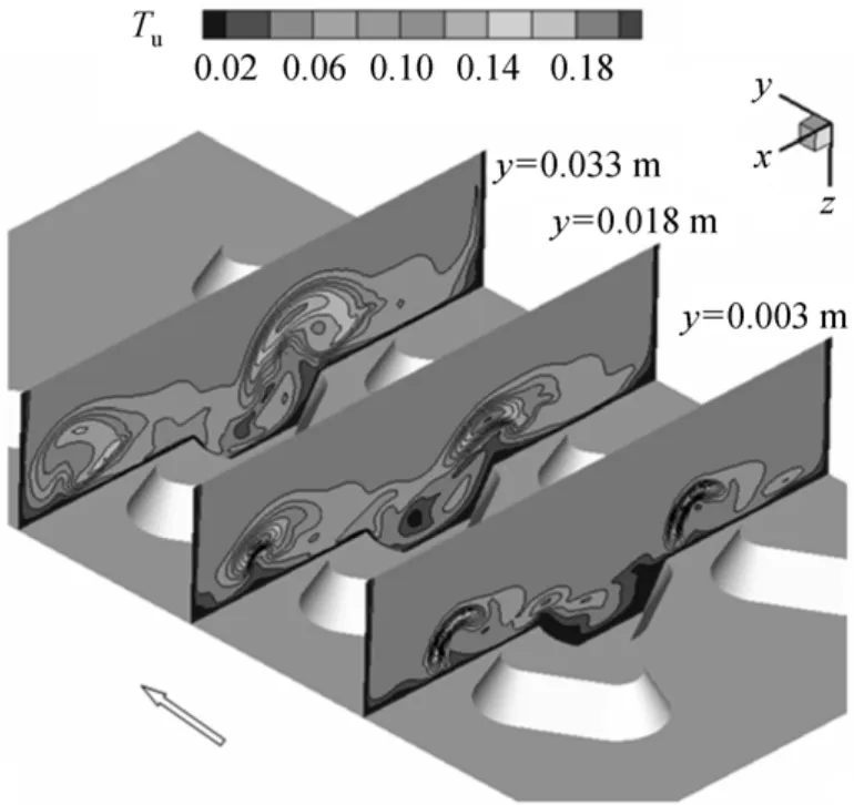
Figure 12 Distribution of turbulent intensity (Tu) on the transversal plane for ribbed-grooved channel at Re 8031 and Case 1
Figure 13 shows the local Nusselt number distribution in ribbed and ribbed-grooved channels at Re 8031 respectively. It is seen that the maximum value of local Nu is located at the leading edge of ribs and the windward side of ribs because of fluid impingement on windward side of ribs and intensified turbulent flow in these regions. The local Nu changes greatly at the lateral side of ribs. This is due to the velocity fluctuation and horseshoe vortex in these regions, so that the thermal boundary layer is disrupted intensely. The local Nu is also high on the rear side of grooves where the recirculation and secondary flow is enhanced, so the contribution to the total heat transfer enhancement is made by the secondary flow in the flow field. It is noted that the Nu is increased on the flat plate near the rear edge of the grooves due to the flow ejection. The region with high Nu appears from the second groove because more fluids are oriented to the grooved region by the ribs. On the other hand, the Nu value is lower behind the ribs. The reason is that the velocity in the wake zone is low and the removal of thermal energy is reduced.
Figure 14 indicates the comparison of streamwise Nu distribution at x=0 between ribbed channel and ribbed-grooved channel. Upstream Nuyof the ribbedgrooved channel is almost the same as that of the ribbed channel and the thermal boundary layer develops gradually. At y=0 Nuydecreases significantly at the front edge of the first groove because of the flow separation. After that, Nuyincreases gradually due to flow attachment inside the groove. With the developing boundary layer Nuydecreases again. At the rear edge of groove, Nuyattains local maximum due to flow re-attachment. Overall, Nuyat the central line of ribbedgrooved channel is larger than that of ribbed channel.
Figure 15 shows the local Nusselt number distribution on the transversal plane for the ribbed channel and ribbed-grooved channel at Re=8031. The region with the high Nu near the ribs is attributed to the longitudinal vortices on the cross section. This is because the secondary flow enhances the mixing of the hot water near the walls and the cold water in the middle of the channel. Downstream, the effects of groove on the heat transfer are stronger due to rib-oriented flow and mixing enhancement. The increasing heat transfer rates inside the grooves are mainly induced by the flow attachment and “tornado-like” flow in this region.
7 CONCLUSIONS
In the present work, experimental and numerical investigations on overall heat transfer characteristics,friction factor and overall thermal performance ratio in rectangular channels with ribs and ribs-grooves have been conducted. By computation, the effects of different slope angles and rib pitches on the overall heat transfer and flow resistance in ribbed-grooved channel also have been studied. The main conclusions are obtained as follows:
(1) The experimental results show that the Nusselt number ratio and friction factor ratio in ribbed-grooved channel are higher than that in ribbed channel without grooves. Compared with ribbed channel, the overall thermal performance of ribbed-grooved channel is increased by about 10%-13.6%.
(2) The numerical results indicate that among four cases of different slope angles considered in the present study, the heat transfer coefficient for Case 1 is the highest; Case 2 shows the most superior thermohydraulic performance; The overall thermo-hydraulic performance ratio for Case 2 is improved by approximately 18%-36%, compared to Case 4.
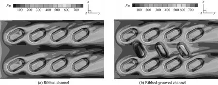
Figure 13 Distribution of local Nusselt number (Nu) on the bottom surface at Re=8031

Figure 14 Streamwise Nu distribution at x=0 of ribbed and ribbed-grooved channel at Re=8031○ ribs-grooves; □ ribs without grooves

Figure 15 Spanwise Nusselt number of different cross section for ribs and ribs-grooves at Re=8031□ ribs without grooves; ○ ribs-grooves
(3) From the numerical results, it is observed that the overall thermo-hydraulic performance ratio for crossed, discontinuous ribs-grooves (Case 2) is improved by about 10.1%-19.4% compared with the cases for V-shape ribs.
NOMENCLATURE
A heat transfer area, m2
Dhchannel hydraulic diameter, m
e rib height, m
f friction factor
h heat transfer coefficient, W·m?2·K?1
I electric current
κ turbulence kinetic energy, m2·s?2
Nu Nusselt number
Pr Prandtl number
p rib pitch, m
?p pressure drop, Pa
Q heat transfer rate, W
Re Reynolds number
T temperature, K
Tuturbulent intensity
?T temperature difference, K
u mean flow velocity, m·s?1
V voltage
W channel width, m
x coordinates, mm
z coordinates, mm
α inclination angle, (°)
η thermal enhancement factor
λ thermal conductivity, W·m?1·K?1
μ molecular viscosity, kg·m?1·s?1
ρ density, kg·m?3
ω dissipation of turbulent kinetic energy, s?1
Subscripts
b bulk
w wall
0 flat plate
1 Sara, O.N., Pekdemi, T., Yapici, S., Yilmaz, M., “Heat-transfer enhancement in a channel flow with perforated rectangular blocks”, Int.J. Heat Fluid Flow, 22 (5), 509-518 (2001).
2 Webb, R.L., Principles of Enhanced Heat Transfer, John Wiley Sons,Chichester (1994).
3 Hu, Z.J., Shen, J., “Heat transfer enhancement in a converging passage with discrete ribs”, Int. J. Heat Mass Transfer, 39 (8), 1719-1727 (1996).
4 Eiamsa-ard, S., Promvonge, P., “Thermal characteristics of turbulent rib-grooved channel flows”, Int. Commun. Heat Mass Transfer, 36(7), 705-711 (2009).
5 Eiamsa-ard, S., Promvonge, P., “Influence of double-sided delta-wing tape insert with alternate-axes on flow and heat transfer characteristics in a heat exchanger tube”, Chin. J. Chem. Eng., 19 (3),410-423 (2011).
6 Kaewkohkiat, Y., Kongkaitpaiboon, V., Eiamsa-ard, S., Pimsarn, M.,“Heat transfer enhancement in a channel with rib-groove turbulators”, AIP Conf. Proc., 1207 (1), 311-316 (2010).
7 Bilen, K., Cetin, M., Gul, H., Balta, T., “The investigation of groove geometry effect on heat transfer for internally grooved tubes”, Appl.Therm. Eng., 29 (4), 753-761 (2009).
8 Layek, A., Saini, J.S., Solanki, S.C., “Effect of chamfering on heat transfer and friction characteristics of solar air heater having absorber plate roughened with compound turbulators”, Renew. Energy,34 (5), 1292-1298 (2009).
9 Layek, A., Saini, J.S., Solanki, S.C., “Heat transfer and friction characteristics for artificially roughened ducts with compound turbulators”, Int. J. Heat Mass Transfer, 50 (24), 4845-4854 (2007).
10 Song, W.M., Meng, J.A., Li, Z.X., “Numerical study of air-side performance of a finned flat tube heat exchanger with crossed discrete double inclined ribs”, Appl. Therm. Eng., 30 (13), 1797-1804 (2010).
11 Li, X.W., Meng, J.A., Guo, Z.Y., “Turbulent flow and heat transfer in discrete double inclined ribs tube”, Int. J. Heat Mass Transfer, 52(3), 962-970 (2009).
12 Shah, R.K., London, A.L., Laminar Flow Forced Convection in Ducts, Academic Press, Inc., New York (1978).
13 Gnielinski, V., “New equations for heat and mass transfer in turbulent pipe and channel flows”, Int. Chem. Eng., 16 (2), 359-368 (1976).
14 Petukhov, B.S., Hartnett, J.P., Advances in Heat Transfer, Vol.6,Academic Press, New York, 504-564 (1970).
15 Yang, S.M., Tao, W.Q., Heat Transfer, Higher Education Press, Beijing (2006). (in Chinese)
16 Kline, S.J., McClintock, F.A., “Describing uncertainties in single-sample experiment”, ASME Mech. Eng., 75, 3-8 (1953).
17 Peng, W, Jiang, P.X., Wang, Y.P., Wei, B.Y., “V-shape ribs Experimental and numerical investigation of convection heat transfer in channels with different types of ribs”, Appl. Therm. Eng., 31 (13),2702-2708 (2011).
2011-11-24, accepted 2012-02-25.
* Supported by the Guangdong Science and Technology Project (2008A01070003).** To whom correspondence should be addressed. E-mail: cedshzhu@scut.edu.cn
 Chinese Journal of Chemical Engineering2012年2期
- Chinese Journal of Chemical Engineering的其它文章
- Optimization for Production of Intracellular Polysaccharide from Cordyceps ophioglossoides L2 in Submerged Culture and Its Antioxidant Activities in vitro*
- A Pilot-scale Demonstration of Reverse Osmosis Unit for Treatment of Coal-bed Methane Co-produced Water and Its Modeling*
- ECT Image Analysis Methods for Shear Zone Measurements during Silo Discharging Process*
- Temperature-triggered Protein Adsorption and Desorption on Temperature-responsive PNIPAAm-grafted-silica: Molecular Dynamics Simulation and Experimental Validation*
- Adsorptive Thermodynamic Properties and Kinetics of trans-1,2-Cyclohexandiol onto AB-8 Resin
- Tracking Submicron Particles in Microchannel Flow by Microscopic Holography*