
Simulation of liquid cone formation on the tip apex of indium field emission electric propulsion thrusters
2024-04-24 06:17:24YimingSUN孫逸鳴HanwenDENG鄧涵文XinyuLIU劉欣宇andXiaomingKANG康小明
Plasma Science and Technology 2024年4期
Yiming SUN (孫逸鳴),Hanwen DENG (鄧涵文),Xinyu LIU (劉欣宇) and Xiaoming KANG (康小明),*
1 School of Mechanical Engineering,Shanghai Jiao Tong University,Shanghai 200240,People’s Republic of China
2 Innovation Academy for Microsatellites,Chinese Academy of Sciences,Shanghai 201210,People’s Republic of China
Abstract Field emission electric propulsion (FEEP) thrusters possess excellent characteristics,such as high specific impulse,low power requirements,compact size and precise pointing capabilities,making them ideal propulsion devices for micro-nano satellites.However,the detection of certain aspects,such as the evolution process of the liquid cone and the physical quantities at the cone apex,proves challenging due to the minute size of the needle tip and the vacuum environment in which they operate.Consequently,this paper introduces a computational fluid dynamics (CFD) model to gain insight into the formation process of the liquid cone on the tip apex of indium FEEP.The CFD model is based on electrohydrodynamic (EHD) equations and the volume of fluid (VOF) method.The entire cone formation process can be divided into three stages,and the time-dependent characteristics of the physical quantities at the cone apex are investigated.The influences of film thickness,apex radius size and applied voltage are compared.The results indicate a gradual increase in the values of electrostatic stress and surface tension stress at the cone apex over an initial period,followed by a rapid escalation within a short duration.Apex configurations featuring a small radius,thick film and high voltage exhibit a propensity for liquid cone formation,and the cone growth time decreases as the film thickness increases.Moreover,some unstable behavior is observed during the cone formation process.
Keywords: FEEP,needle emitter,liquid cone formation,CFD simulation
1.Introduction
As a novel electric propulsion technology,field emission electric propulsion (FEEP) offers precise thrust ranging from severalμN to hundreds ofμN while maintaining low thrust noise [1].FEEP possesses several advantages,including high specific impulse,compact form factor and long service life,making it highly suitable for drag compensation,attitude control and orbit maintenance for nano-satellites [2].According to the wetting properties of the propellant,FEEP can be categorized into needle,capillary,and porous types [3–6].The solid needle-type FEEP features a micro-sized tungsten tip,which exhibits high electrical impedance,operates at a low firing voltage,and facilitates thrust clustering to generate substantial propulsion [7].Indium serves as a recommended propellant due to its melting point (156 °C),enabling it to solidify and withstand vibrations during launch.
The development of indium-needle FEEP is based on the technology of the liquid metal ion source (LMIS) [8].LMIS comprises a heater assembly,an extractor,and a needle emitter that is wetted by liquid metal,as illustrated in figure 1.When the heater assembly heats liquid metal propellant to its melting point and a high electric potential is applied within the space between the emitter and extractor,the liquid bumps on the tip apex due to the combined effects of electrostatic force and surface tension stress.Subsequently,it undergoes growth,forming a conical cone,a so-called Taylor cone,with a cusp protrusion at the apex,until the electric field at the cusp apex reaches a critical level,with ion emission occurring [9].Simultaneously,the presence of fluid negative pressure at the cone apex propels the liquid metal to flow along microgrooves on the surface towards the apex of the cone,which serves to replenish the already ejected ions [10,11].
The formation and evolution of the liquid cone on the tip apex constitute the fundamental physical processes underlying FEEP.These processes involve complex interactions among electrostatic forces,surface tension and fluid flow.Taylor was the first to establish a theoretical analysis of liquid cone formation,considering the static equilibrium between electrostatic forces and surface tension pressure and ignoring liquid flow and ion emission [12].Under these assumptions,the half-cone angle was derived as 49.3° when a critical voltage was applied between the emitter and extractor.Kingham and Swanson adopted a model of a jet-like protrusion on the end of a Taylor cone and found that the cusp apex radii were typically in the order of a few tens of angstroms with protrusion lengths ranging from 400 ? to 500 ? [13].Early models of cone-jet formation focused on the quasi-equilibrium of the liquid cone surface.In later studies,Burton and Taborek simulated the dynamic evolution process of charged inviscid droplets and observed that the droplets become unstable with small perturbations,ultimately forming a lemon shape with a sharp tip [14].Suvorov presented an electrohydrodynamic model that described the dynamic behavior of the Taylor cone using the Navier–Stokes equations and considered free liquid boundaries subject to Maxwell field stress,surface tension stress and viscous effects [15].However,the calculations in this model assumed a flat needle tip,whereas the fabricated conical needle tip typically has an approximately hemispherical apex.Several scholars have indirectly or directly observed the formation of the liquid cone.Wagneret alobserved the rapidly frozen liquid cone on the tip apex while operating at approximately 20μA [16].In addition,dynamic instabilities were also found on the needle shank behind the Taylor cone by a 200 keV transmission electron microscope,resulting in microdroplet emission.Praprotniket alobserved the in situ shape of the liquid cone in indium LMIS with ion emission using a 1 MeV electron transmission microscope [17].It was noted that the jet length increased and the cone angle decreased with increasing emission current.However,due to the interference of electric fields and the limitation of exposure speed,precise observation of the transient response during operation using an electron microscope is challenging.Recently,some CFD codes have been employed to simulate the dynamic behavior of cone formation of aqueous solution or ionic liquid.Senet alsimulated the cone-jet electrospray on carbon nanofiber emitters using a CFD code(FLOW-3D) and demonstrated the feasibility of these simulations [18].Liuet alsimulated the meniscus formation of an ionic liquid in the electrospray process and found that the alternation of polarity can delay the cone growth time [19].Heet alsimulated the droplet emission process on capillary standing waves under the dual action of electric field and vibration by a CFD software FLUENT [20,21].In addition to CFD methods,molecular dynamics has been utilized to investigate the formation of the liquid cone by computing the interaction between atom and field.Zhanget alstudied Taylor cone formation and the electrospray jet process of capillary emitters at an atomistic scale [22].However,due to computational costs,the model was considerably simplified relative to the real system using scaling laws [23].
Despite significant effort dedicated to investigating the liquid cone phenomenon,little attention has been given to the cone formation process and the evolution of physical quantities at the cone apex over time.This lack of attention can be attributed to the challenges associated with observation and measurement.Since the needle emitter cannot be operated and directly observed in the atmosphere due to the liquid metal’s susceptibility to oxidation,this creates the issues of focus and capture in the vacuum chamber.The apex radius of the needle is typically several micrometers,and the distance of the counter electrodes is in the order of tens of microns.The jet diameter of the cusp on the cone apex in the range of sub-microns is too small to be observed through optical cameras.In addition,measuring physical quantities,such as the electric field on the fluid surface and pressure beneath the cone apex,is nearly impossible.Therefore,numerical simulation provides a more feasible approach for studying the formation of the liquid cone in FEEP.In this regard,we have developed a computational fluid dynamics (CFD) model of FEEP utilizing a solid needle emitter.This model aims to enhance the understanding of the fundamental characteristics and formation process of the liquid cone at the tip apex.
The structure of the paper is organized as follows.Section 2 provides an overview of the electrohydrodynamic theory,which is employed to describe the behavior of the liquid during the cone formation process.Section 3 presents the analysis and establishment of the CFD model.In section 4,the evolution of the liquid cone on the tip apex is investigated,and the time-dependent characteristics of physical quantities at the cone apex are revealed.In addition,the influence of film thickness,apex radius and applied voltage on cone growth time and free surface shape is examined and compared.This section also addresses the discussion of instabilities observed during the formation process of the Taylor cone.Finally,in section 5,a summary of the work is provided.
2.Theory
The CFD simulation is based on the Taylor–Melcher dielectric fluid model and the EHD equations [24,25].To precisely capture the free surface between the air and liquid phases,the volume of fluid (VOF) method [26] is applied.This is facilitated through the utilization of FLOW-3D,a dedicated CFD software.FLOW-3D offers various physics modules that are internally integrated,allowing users to select and couple multiple modules for calculations.In this simulation,the modules of electro-mechanics,surface tension and viscosity are specifically employed to analyze the liquid cone formation process on the tip apex of the FEEP thruster.
The equation of fluid continuity and the Navier–Stokes equation were used to describe the dynamic behavior of the liquid cone formation.Assuming that the liquid is incompressible (of constant densityρ) and has the constant viscosityμ.The gravity term can be omitted,considering the size of the liquid cone (several micrometers).It can be described as,
whereuis the fluid velocity,Pis the hydrodynamic pressure andFeis the body force.The convective effects induced by temperature primarily stem from viscosity and conductivity.Given the constant operational temperature of the thruster,the size of the liquid cone (several micrometers),and the transient formation process (several microseconds),it is reasonable to neglect variations in viscosity and conductivity,treating them as constants.Therefore,electromechanical forces are the main driving force inFe,and the electrostatic force is expressed as,
whereρeis the net free charge density,Eis the electric field strength,ε0is the vacuum permittivity andεlis the fluid dielectric constant.The first term on the right is Coulomb force due to the free charge on the liquid surface,and the second term is polarization force arising from polarization effects.
The governing equation for the electric potential and electric field in the fluid is given by the Laplace equation:
The law of charge conservation on the vacuum-liquid interface is as follows:
wherenis the unit normal vector andσis the electric conductivity of the liquid.At the interface,there is a jump in the electric field in the normal direction due to surface charge density,while the electric field in the tangential direction is continuous:
whereφlis the electric potential in the liquid,φvis the electric potential in the vacuum,εvis the relative permittivity of the vacuum,qis the electric charge quantity andtis the unit tangential vector.The mechanical equilibrium condition at the normal direction of the interface is,
whereTeis the electrostatic stress tensor,Tfis the fluid stress tensor andγis the surface tension coefficient.In the VOF method,the motion of the interface is governed by the kinematic equation:
The interface is tracked by the volume fraction functionF:
where 1 represents the cell occupied by the liquid,and 0 is the vacuum.Equations are solved in FLOW-3D by choosing appropriate boundaries and initial conditions.
3.Modelling and validation
3.1. Modelling of the liquid cone formation process
In the FEEP system,the needle emitter is typically fabricated by electrochemical etching.The apex radius of the tip ranges from several micrometers,as shown in figure 2(b),while the liquid film thickness is in the range of tens to hundreds of nanometers [10].However,the dimensions of the needle tip length and extractor diameter are in the order of several millimeters,as depicted in figure 2(a).This significant difference in dimensions makes it challenging to simulate the entire flow on the needle tip surface and apex.
In this study,our focus is on the process by which the liquid film forms a liquid cone on the needle tip.Consequently,the needle tip geometry can be approximated by a solid hemisphere uniformly covered by a liquid film,as illustrated in figure 3(a).The physical parameters of liquid indium [27–29] including fluid densityρ,viscosityμ,electrical conductivityσand surface tension coefficientγare listed in table 1.Figure 3(b) depicts the solid disk extractor placed 100μm above the emitter.A positive voltageΦ=V0is applied to the tip hemisphere,while the extractor is set to zero voltageΦ=0,creating a high electric field between the two electrodes.The no-slip wall condition of fluidu=0 is imposed on the tip surface.As the tip is approached,the area near the apex has no grooves [30],as shown in figure 2(b).
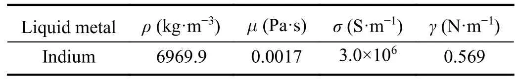
Table 1.Physical properties of the liquid indium.
Thus,the tip apex can be considered smooth in this model.The geometry in this model exhibits cylindrical symmetry around thez-axis,allowing the use of cylindrical coordinates and mesh for computational simplification.Mesh convergence study was conducted in figure 4,in order to ensure that the results are mesh independent.The results indicate that a mesh size less than or equal to 0.25μm has sufficient refinement to obtain a better resolution.Considering the balance between resolution and computational efficiency,the fluid domain employs a mesh size of 0.25μm,while the spatial domain is assigned a mesh size of 0.5μm.The simulation domain encompasses a radial dimension of 6μm and an axial dimension of 120μm.Boundaries 1 and 2 are set as the outflow boundary,and boundary 3 represents the boundary wall.
3.2. Validation of the established model
To verify the accuracy of the established model,an experimental approach was conducted by freezing the liquid cone on the tip apex and observing it using an electron microscope.In the experiment,a tungsten tip with an apex radius of 5μm was wetted with liquid indium,resulting in a film thickness of 0.4μm at the tip apex estimated from the SEM image.The distance between the counter electrode and the emitter was adjusted to 100μm.The liquid cone was frozen while operating at emission current of 18μA,a voltage of 7.5 kV and a pressure of 5×10⁻⁴Pa.The simulation used the same parameters as those in the experimental setup.
Figure 5(a) displays the scanning electron microscope(SEM) image of the frozen Taylor cone on the tip apex obtained from the experiment.Figure 5(b) illustrates the simulation results of the liquid cone shape.The cone shape obtained from the simulation exhibits a better consistency than the experimental results.The measured cone angle of the frozen cone is 98.5°,with an error of 6.7% when compared to the simulated value of 91.9°.Furthermore,the model undergoes validation by simulating the onset voltage,and the results are compared with the experimental data presented in figure 6.To ensure consistency,identical wetting processes and parameters are employed,maintaining a uniform film thickness of 0.4μm on the needle tip,with a fixed distance of 200μm between the counter electrode and the emitter.The results show a slight discrepancy between simulation and experimentation,with the simulation values averaging approximately 4% higher than the experimental results.These results indicate a reasonable agreement between the simulation and experimental observations,validating the accuracy of the established model.
3.3. Parameters set in the simulation
The tip apex radius can be fabricated at a desired value through electrochemical etching and a roughening process.However,it is common for the apex radius to be processed below 10μm due to considerations of low onset voltage and high mass efficiency [31,32].For the purpose of comparison,a typical tip radius of 5μm was chosen,while 3μm and 7μm were used as alternative values.The film thickness represents the degree of wetting,with a thicker film indicating a better wetting degree.A minimum film thickness of 0.3μm is required [33].Consequently,a film thickness ranging from 0.3 to 0.7μm was employed to examine the impact of different film thicknesses.In the simulation,the applied voltage is set near the onset voltage corresponding to the apex radius.Furthermore,different voltages are applied to the same apex radius in order to investigate the influence of voltage.
4.Results and discussion
4.1. Evolution of the liquid cone
The parameters utilized in the current model are as follows:an apex radius of 5μm,a film thickness of 0.5μm,an applied voltage of 6210 V.The counter electrode is positioned at a distance of 100μm from the tip apex.The formation process of the liquid cone can be divided into three stages,as depicted in figure 7.Stage 1: the liquid film is a hemisphere shape at the initial stage.Over time (0.6–1.2μs),the liquid gradually converges from both sides of the tip towards the apex under the influence of the electric field.At 2.09μs,a thicker fluid accumulates at the apex,resulting in a bump shape.It is observed that the formed conical liquid cone has an approximate half angle of 42° at 2.4μs,slightly smaller than the theoretical value of the Taylor cone (49.3°).This deviation is attributed to the fact that the system is not in static equilibrium during the movement of the liquid.In this first stage,the initial hemisphere liquid film redistributes due to the electrically driven process.Stage 2: from 2.4 to 2.71μs,the height of the liquid continues to increase,and the cone apex becomes sharper.By 2.71μs,the Taylor cone is essentially formed.During this stage,the apex radius of the cone gradually decreases,approaching the characteristics of a Taylor cone.Stage 3: from 2.71 to 2.74μs,the cone cusp is further protruded due to the high electric field acting on the small surface of the cusp apex.At 2.74μs,the cone jet is formed with a half angle of 38.7°.Subsequently,microdroplets are emitted in the cone jet area.In this stage,the cone jet is fully developed,and microdroplet emission occurs.Figure 8 illustrates the electric field intensity along thez-axis (symmetry axis) during the evolution of the liquid cone,and the center of the hemisphere is thez-zero point.Initially,the electric field intensity is low,but as the liquid cone gradually forms,the electric field at the cone apex increases,reaching values ranging from 108to 109V·m-1.The electric field at the cone apex reaches 1.3×10⁹V·m-1at 2.7μs,achieving the ionized field threshold.It is important to note that FLOW-3D is a simulation software primarily designed for fluid dynamics.As such,it can effectively simulate the entire formation process of the liquid cone.However,it should be highlighted that the subsequent ion emission mechanism is field emission.Consequently,FLOW-3D can only accurately simulate the formation process of the cone jet,and after that it will transit into the droplet emission stage instead of the actual ion emission state.
4.2. Time-dependent characteristic of physical quantities at the cone apex
Figure 9(a) illustrates the time dependence of electrostatic stress and surface tension stress at the cone apex.These physical quantities exhibit a distinct characteristic of gradually increasing values over an extended period,followed by a rapid escalation within a short duration.The evolution of stress growth can also be divided into three stages corresponding to liquid cone growth.In the initial stage,stress increases slowly over time,with the shape of the liquid cone also changing slowly during this time.Advancing to the second stage,due to the liquid cone shape basic formation,stress increases at a quicker rate.Finally,in the third stage,because of the cone cusp protrusion and high electric field action,stress experiences a rapid and run-away escalation.It can be observed at 2.74μs that the electrostatic stress surpasses and is much larger than the surface tension stress.The Bernoulli equation at the cone apex can be expressed as,
wherePis the pressure,ρis the density,uis the fluid velocity,Teis the electrostatic stress,Tfis the surface tension stress and δ is the strain due to the fluid stretching.From the equation and figure 9(a),it can be analyzed that the unequal values of electrostatic and surface tension stress include contributions from kinetic energy density and negative pressure beneath the cusp.The negative pressure plays a role in driving the flow of liquid on the surface of the needle.Figure 10 presents the pressure distribution within the liquid cone during its evolution.Notably,there is a region of negative pressure beneath the cone apex.Figure 9(b) is the shape of the liquid level obtained by approximating the fluid mesh points.The horizontal axis is in the radial direction and the vertical axis is in thezdirection (symmetry axis).By comparing the surface shapes throughout the evolution process in figure 9(b),it becomes apparent that the onset of the run-away behavior coincides with the formation of a quasi-conical surface shape.As the conical liquid cone develops,the cone apex area and radius shrink with increasing cone height,leading to the rapid growth of electrostatic stress and surface tension stress.
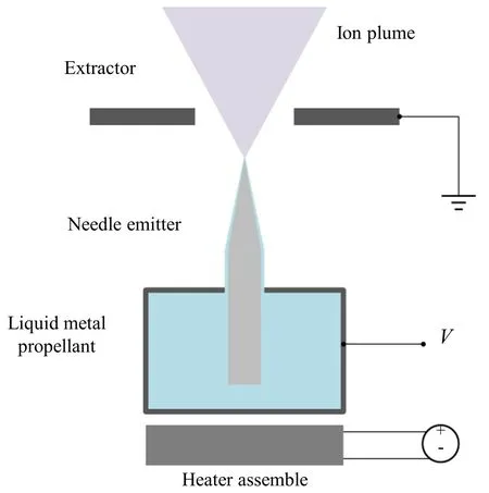
Figure 1.Schematic of the needle-type FEEP setup.
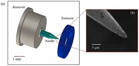
Figure 2.Comparing the macro size of the FEEP thruster with the micro size of the tip apex.(a) Schematic setup of the FEEP thruster and (b) SEM image of the needle tip and tip apex.
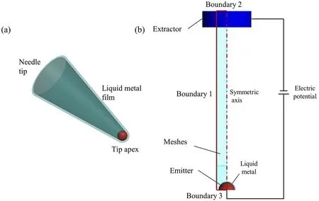
Figure 3.Modeling and meshing of the emission process.(a) Model of the needle tip wetted by a film of liquid metal and (b) meshes and boundary conditions.
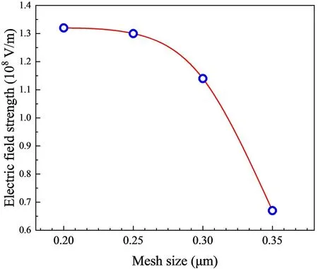
Figure 4.Maximum electric field strength versus mesh size.
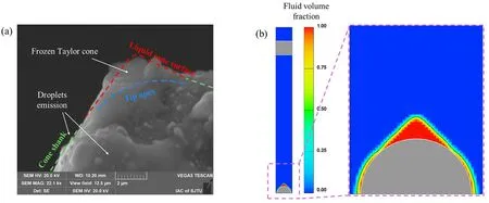
Figure 5.Comparison of the cone shape in a frozen Taylor cone with the simulation result.(a) Frozen Taylor cone of liquid metal indium at the tungsten tip and (b) the simulation result.
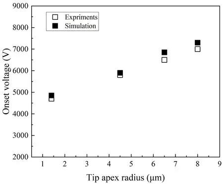
Figure 6.Onset voltage versus tip apex radius.
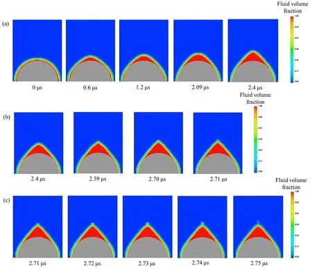
Figure 7.The formation process of the Taylor cone at the apex radius of 5 μm,applied voltage of 6210 V and film thickness of 0.5 μm.(a) First stage,(b) second stage and (c) third stage.
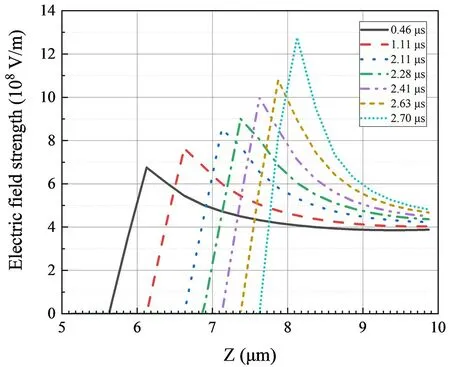
Figure 8.Evolution of the electric field strength along the z-axis in the liquid cone formation.
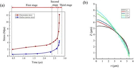
Figure 9.Time-dependent behavior at the cone apex.(a) Electrostatic stress and the surface tension stress at the cone apex and (b) variation of the free surface shape.
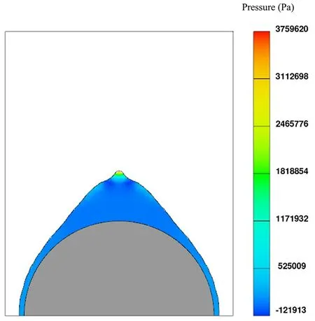
Figure 10.The pressure distribution inside the liquid cone during evolution at 2.56 μs.
In figure 11(a),the cone-apex velocity along thez-axis exhibits behavior similar to the time-dependent stress acting on the liquid surface.During the stage of liquid accumulation,the velocity increases gradually over an extended period and then rapidly escalates.Prior to the occurrence of emission,the velocity of the cone apex reaches a value of 33 m·s-1.In addition,the position of the cone apex also follows the same pattern of motion.Although the ion emission process cannot be represented with FLOW-3D,the charged microdroplets generated during the actual highcurrent situation can be reflected and investigated in the simulation.Figure 11(b) illustrates the velocity distribution of the charged microdroplets along thez-axis.It is observed that the velocity of the microdroplets jetted from the cusp exhibits a linear distribution and the maximum velocity is 35100 m·s-1.
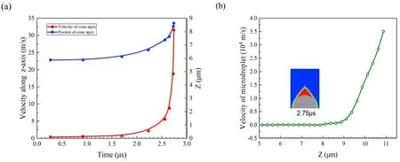
Figure 11.Motion of liquid surface and microdroplet emission at the cone apex.(a) Variation of the fluid position velocity of the cone apex and (b) velocity distribution of the jetted microdroplet.
4.3. Influence of the film thickness,apex radius and applied voltage
Figure 12 presents the influence of film thickness on the cone growth time,considering an apex radius of 5μm and an applied voltage of 6210 V.The results indicate that the cone growth time decreases as the film thickness increases.In other words,a thinner film requires more time to form the Taylor cone.This behavior can be attributed to the difficulty of liquid flow towards the apex when a thin film is present,due to the viscous drag near the solid boundary.At thinner film thicknesses,the viscous effect becomes dominant,resulting in a longer time for the liquid cone to form.As the film thickness increases,the influence of viscosity on the formation time gradually weakens.
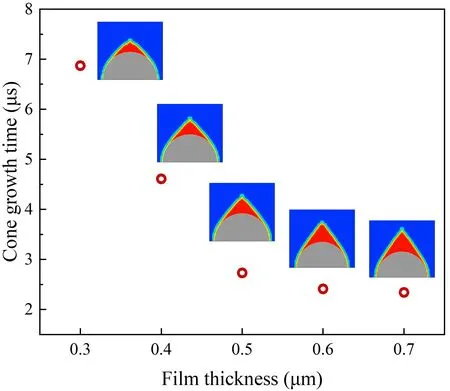
Figure 12.Formation time of the Taylor cone as a function of film thickness.
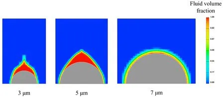
Figure 13.Formations of the liquid cone with different apex radii of 3 μm,5 μm and 7 μm.
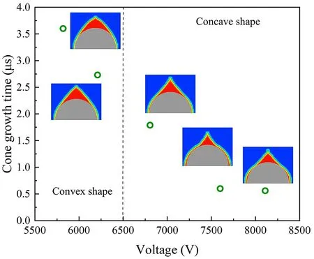
Figure 14.Formation of the Taylor cone at different applied voltages.
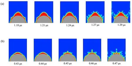
Figure 15.Unstable formations of the liquid cone.(a) Microdroplets occurring at the bottom of the Taylor cone with the film thickness of 0.8 μm and voltage of 7200 V and (b) fragmentation of the liquid cone in the formation process with the film thickness of 0.5 μm and voltage of 7980 V.
In figure 13,the formation of the liquid cone at different apex radii is depicted,considering a film thickness of 0.5μm and an applied voltage of 5820 V.It can be seen that the tip apex with a radius of 5μm exactly forms the Taylor cone,as the applied voltage approaches the onset voltage.Furthermore,the tip apex with a smaller radius of 3μm is more prone to forming the Taylor cone.However,the tip apex with a larger radius fails to generate a liquid cone.This discrepancy can be explained by considering the interplay between the liquid film and the walls.In the case of a thick film (0.5μm) relative to the apex radius of 3μm,the influence of viscosity can be neglected.Moreover,the sharp apex at the initial stage results in a higher electric field at the liquid surface and promotes the redistribution process driven by the electrostatic force.Consequently,the combination of a blunt apex and a thin film leads to the unsuccessful formation of the liquid cone at an apex radius of 7μm.
In figure 14,the influence of different voltages on the cone formation time is investigated,considering an apex radius of 5μm and a film thickness of 0.5μm.The results show that the cone growth time decreases with the applied voltage.Because of the higher voltage,the electrostatic stress at the liquid surface impels the faster formation of the liquid cone.In addition,at a low voltage of 5820 V,the surface of the liquid cone exhibits a convex shape,while the jet of the liquid cone becomes slender,and the height rises with the increase in voltage.This phenomenon can be explained by the self-shaping characteristic of LMIS,where changes in the field strength not only extend the cone-jet length but also result in a decrease in the half angle,and a concave shape of the cone surface.The simulation results presented in figure 14 are in good agreement with the experiments conducted by Benassayaget al[34],who observed the dynamic formation of the liquid cone on the tip of Ga-LMIS using anin situ3 MeV electron transmission microscope.Furthermore,Praprotniket al[17] also observed the dynamic behavior of the indium liquid cone and the cone jet process using anin situmethod.
4.4. Instabilities during the formation of the Taylor cone
It is found in the simulations that Taylor cones do not form stably under all conditions.Two typical cases analyzed below demonstrate the potential instabilities that can occur during the formation of the Taylor cone,highlighting the importance of parameters,such as film thickness,applied voltage and wetting properties,in achieving stable cone formation and emission processes.
The first case of the instabilities of the Taylor cone in the simulation is investigated with a film thickness of 0.8μm and an applied voltage of 7200 V,as shown in figure 15(a).When the liquid film is thick and the applied voltage (emission current) is high,the liquid surface is unstable and turbulent flow occurs in the cone formation process.As a result,microdroplets,known as Faraday droplets,with diameters of a few tenths of a micron are emitted from the shank of the liquid cone [16,35].The instability is likely triggered by surface waves that form during the liquid cone formation process.It is found that this situation occurs in a specific combination of liquid film thickness and high-voltage parameters.
In the second case,depicted in figure 15(b),a film thickness of 0.5μm and an applied voltage of 7980 V are used.When the liquid film is relatively thin and the voltage is high(or the emission current is high),the speed at which the bump of the liquid at the apex moves is greater than the speed at which the surrounding fluid flows towards the apex,resulting in cone jet fragmentation and the formation of microdroplets.This results in the liquid being unable to replenish the fluid needed for cone formation,leading to the collapse of the cone and the emission of Rayleigh droplets[36,37].The second instability case has smaller scale of emitted droplets and higher frequency compared with the first case.This situation can be observed in needles with a poor wetting film when there is oxide contamination on the liquid metal surface or a discontinuous crack liquid film due to thermo stress during cyclic heating of the thruster,causing high flow impedance and forming unstable emission.
5.Conclusion
The CFD simulations presented in this work are demonstrated to be capable of predicting the physical quantities in the liquid cone,and provide valuable reference in FEEP design and performance evaluation.The following conclusions can be drawn:
(1) Employing EHD equations and the VOF method to describe fluid behavior and track the free surface,the model accurately captures the formation of the liquid cone on the micro tip apex.The formation process can be divided into three stages: liquid hump at tip apex,liquid cone basic formation,cone apex protrusion and cone jet formation.
(2) The simulation results reveal interesting behavior of various physical quantities at the cone apex such as electrostatic stress,surface tension stress and velocity.These quantities exhibit a run-away behavior,slowly increasing over a long time and then rapidly becoming very large within a short time.This behavior is closely related to the formation of the quasi-cone structure.
(3) The film thickness is identified as a significant factor influencing the formation of the liquid cone on the tip apex.The cone growth time decreases as the film thickness increases due to the viscous drag acting close to the solid boundary.However,when the liquid film becomes sufficiently thick,the influence of viscosity becomes negligible.
(4) The simulation also indicates that the formation of the liquid cone is more likely with a smaller apex radius under the same film thickness and applied voltage.The higher the applied voltage,the shorter the cone growth time.Furthermore,increasing the applied voltage leads to an increase in the protrusion length of the cusp and a concave shape of the free surface,resulting in a decrease in the cone angle.
(5) In simulation,microdroplets are sometimes emitted from the shank of the liquid cone.In addition,it is noted that the discontinuity of the liquid metal film caused by poor wetting or cyclic heating can lead to the failed formation and collapse of the Taylor cone.
Overall,the CFD simulation presented in this work provides valuable insight into the behavior of the liquid cone formation and its dependence on various parameters,contributing to the understanding and optimization of FEEP systems.
Acknowledgments
This work was supported by National Natural Science Foundation of China (No.52075334).
 Plasma Science and Technology2024年4期
- Plasma Science and Technology的其它文章
- Experimental results of a magnetic field modification to the radio frequency driver of a negative ion source
- A fringe jump counting method for the phase measurement in the HCN laser interferometer on EAST and its FPGA-based implementation
- Novel method for identifying the stages of discharge underwater based on impedance change characteristic
- Performance of pulsed plasma thruster at low discharge energy
- Dynamic propagation velocity of a positive streamer in a 3 m air gap under lightning impulse voltage
- On the evolution and formation of discharge morphology in pulsed dielectric barrier discharge