
Final results of the first phase of the PROTO-SPHERA experiment: obtainment of the full current stable screw pinch and first evidences of the jet + torus combined plasma configuration
2024-03-19 02:36:42PaoloMICOZZIFrancoALLADIOAlessandroMANCUSOVincenzoZANZAGerardaAPRUZZESEFrancescaBOMBARDALucaBONCAGNIPaoloBURATTIFrancescoFILIPPIGiuseppeGALATOLATEKAFrancescoGIAMMANCOEdmondoGIOVANNOZZIAndreaGROSSOMatteoIAFRATIAlessandroLAMPAS
Plasma Science and Technology 2024年2期
Paolo MICOZZI,Franco ALLADIO,Alessandro MANCUSO,Vincenzo ZANZA,Gerarda APRUZZESE,Francesca BOMBARDA,Luca BONCAGNI,Paolo BURATTI,Francesco FILIPPI,Giuseppe GALATOLA TEKA,Francesco GIAMMANCO,Edmondo GIOVANNOZZI,Andrea GROSSO,Matteo IAFRATI,Alessandro LAMPASI,Violeta LAZIC,Simone MAGAGNINO,Simone MANNORI,Paolo MARSILI,Valerio PIERGOTTI,Giuliano ROCCHI,Alessandro SIBIO,Benedetto TILIA and Onofrio TUDISCO
1 FSN Dipartimento Fusione e tecnologie per la Sicurezza Nucleare,ENEA Agenzia Nazionale per Le Nuove Tecnologie Energia e lo Sviluppo Economico Sostenibile,Frascati (Rome) 00044,Italy
2 IAPS Istituto di Astrofisica e Planetologia Spaziali,INAF Istituto Nazionale di Astrofisica,Rome 0133,Italy
3 Physics Department,University of Pisa Faculty of Natural Sciences Mathematics and Physics,Pisa 56127,Italy
Abstract In astrophysics,the boundary conditions for plasma phenomena are provided by nature and the astronomer faces the problem of understanding them from a variety of observations [Hester J J et al 1996 Astrophys.J. 456 225],on the other hand,in laboratory plasma experiments the electromagnetic boundary conditions become a major problem in the set-up of the machine that produces the plasma,an issue that has to be investigated step by step and to be modified and adapted with great patience,in particular in the case of an innovative plasma confinement experiment.The PROTO-SPHERA machine [Alladio F et al 2006 Nucl.Fusion 46 S613] is a magnetic confinement experiment,that emulates in the laboratory the jet + torus plasma configurations often observed in astrophysics: an inner magnetized jet of plasma centered on the(approximate) axis of symmetry and surrounded by a magnetized plasma torus orthogonal to this jet.The PROTO-SPHERA plasma is simply connected,i.e.,no metal current conducting rod is linked to the plasma torus,while instead it is the inner magnetized plasma jet (in the following always called the plasma centerpost) that is linked to the torus.It is mandatory that no spurious plasma current path modifies the optimal shape of the plasma centerpost.Moreover,as the plasma torus is produced and sustained,in absence of any applied inductive electric field,by the inner plasma centerpost through magnetic reconnections [Taylor J B and Turner M F 1989 Nucl.Fusion 29 219],it is required as well that spurious current paths do not surround the torus on its outboard,in order not to lower the efficiency of the magnetic reconnections that maintain the plasma torus at the expense of the plasma centerpost.Boundary conditions have been corrected,up to the point that the first sustainment in steady state has been achieved for the combined plasma.
Keywords: laboratory plasmas,magnetic confinement,astrophysical plasmas
1.Introduction
The PROTO-SPHERA experiment [1] was built at the CRENEA in Frascati in order to study an innovative configuration of plasma magnetic confinement,in view of controlled fusion research,and it is quite different from the confinement experiments studied up to now.PROTO-SPHERA is an attempt to emulate in the laboratory the jet + torus plasma of the Crab Nebula [2,3]: an internal magnetized plasma centerpost (jet) on the axis of symmetry of the configuration,surrounded by a magnetized plasma torus orthogonal to the plasma centerpost,as shown in figure 1.The confined plasma geometry is simply connected,as well as the geometry of the machine that encloses it: no metal conductor is topologically linked to the plasma torus and consequently the vacuum chamber is simply a cylinder.The plasma centerpost is sustained by a DC voltage,applied between electrodes internal to the vacuum vessel,and the plasma torus is formed by self-organization around the plasma centerpost: the lines of force winding around the centerpost are broken and reconnected [4] into lines of force winding around the torus (DC Helicity Injection).The experiment is capable of sustaining the torus as long as the centerpost is kept running,provided that magnetic reconnections are recurring and that the magnetic flux transfer from the jet to the torus is efficient enough.
An unavoidable difference between PROTO-SPHERA and its cosmical examples [5] is that in astrophysics the containment force fulfilling the virial theorem is obviously the gravitational one,whereas in the case of a laboratory experiment the virial theorem must be fulfilled by means of the magnetic field produced by poloidal field coils (PF coils),external to the plasma configuration [6],coils which are responsible for containing the expansive force of the current carrying plasma torus.Another difference,which is less obvious,is that in astrophysics,in the nonrelativistic approximation,the solenoidal condition for the plasma current densityis automatically satisfied everywhere [7]; instead in a laboratory experiment there are nearby metallic conductors,which the plasma can charge,and therefore divergences of the plasma current density can occur.On one hand,the electric charging of these metal surfaces can induce the spontaneous rotation of the plasma around its symmetry axis,which makes the laboratory configuration more similar to the astrophysical ones,while on the other hand,it can trigger the release of secondary spurious plasma currents.We will see in the following that the electrostatic boundary conditions are very critical for the stability of the plasma configuration in the laboratory.
2.Purpose and aims of the experiment
2.1.A confinement experiment based upon magnetic reconnections
The presence of a toroidal fieldBTin PROTO-SPHERA is a straight consequence of Maxwell’s equations (Ampere’s theorem),provided that the electrodes are able to produce the plasma currentICPin the centerpost discharge,according to the design specifications.However,in astrophysical examples and in the PROTO-SPHERA machine,the existence of the confined plasma,i.e.,of a torus carrying a currentIST,around the plasma jet (or centerpost) relies on plasma-dynamic phenomena,in particular on magnetic reconnections,where dissipative phenomena,such as plasma resistivity or viscosity,play a crucial role.It is a general observation that nature is able to form resilient toroidal configurations in fluid media where jet stream forces act.The most obvious fluid-dynamical analogies are the smoke rings,that are produced by straight jets of steam from erupting volcanoes [8] as well as by skilled cigarettes smokers,but also the air rings that are created and supported underwater by playful cetaceans [9].The vortex rings are due to the presence of a jet stream of a fast-moving fluid in a distinct fluid quiescent background.The shear imposed at the interface between the two fluids slows down the outer layer of the fast-moving fluid relatively to the centerline one.The fluid spins around a closed loop forming a toroidal vortex.
In PROTO-SPHERA the magnetic reconnections occur on the ordinary X-points,which exist on two circles,one above and the other below the equator of the machine,as shown in figure 1(a).In the magnetic reconnections,in addition to the transfer of energy,there is also a transfer of magnetic flux and of electric current: in the case of PROTOSPHERA part of the toroidal electric current,which winds inside the plasma centerpost discharge,as seen in figure 1(b),is therefore transferred inside the surrounding torus,right through the tears that occur on the two circles of ordinary X-points.

Figure 1.(a) Poloidal cross-section of PROTO-SPHERA plasma,CP stands for centerpost,ST for torus,the mechanical structures of the poloidal field coils are removed from the scheme.(b) Scheme of a tokamak (top) and of PROTO-SPHERA (bottom): pink colour is for plasma,grey for vessel,orange for metal bars,blue for electrodes.(c) Perspective sketch of the plasma and of the annular electrodes.(d) View of the annular anode (top) and of the annular cathode (bottom).
Many aspects of magnetic reconnection are still today poorly understood [10]: even the reconnection time is assessed differently on the basis of different theoretical models [11].In magnetic confinement experiments magnetic reconnections typically have more adverse than advantageous effects,as often they spoil the integrity of the magnetic toroidal flux surfaces,but a very relevant aspect is their ability to accelerate,out of thermal equilibrium,the plasma electrons: a characteristic that causes sudden x-ray emissions [12].Furthermore,the magnetic reconnections,by converting a part of the magnetic energy of the field into the kinetic energy of the plasma,are also able to heat the plasma[13],by affecting the thermal component of its distribution function; this characteristic makes magnetic reconnections extremely interesting in the pursuit of controlled fusion.A heating method based on natural phenomena,intrinsically produced by the self-organization of the plasma configuration,could prove to be more effective than the heating methods that have to resort to additional heating devices,located outside the machine producing and confining the plasma,as the effort to build the former is often greater than the effort to build the latter.The possibility of obtaining the heating of the plasma by magnetic reconnections is suggested by the astrophysics of the Sun: today a credited hypothesis for the high temperature of the solar corona (from 4500-6000 Kelvin degrees of the underlying solar photosphere to millions of Kelvin degrees of the outer corona) is that it is due to the magnetized flux tubes rising from the thin solar tachocline,crossing the whole convective region of the Sun,piercing the photosphere and the chromosphere and finally undergoing magnetic reconnections (such as solar flares) and releasing thermal energy to the lower density plasma of the solar corona [14,15].
2.2.The PROTO-SPHERA configuration
The PROTO-SPHERA experiment is a magnetic confinement configuration with axial symmetry,just like the tokamak [16]: the plasma,studied in view of controlled fusion nuclear reactions,must take the form of a torus and there are two indispensable requirements for confining it.First there must be a toroidal magnetic fieldBT(directed along the large circle of the torus) and second a poloidal magnetic fieldBpol(directed along the small circle of the torus),this last requirement is equivalent to the presence of a toroidal electric current flowing inside the plasma torus.
The plasma thus becomes organized according to magnetic flux surfaces,each contained inside another; on every flux surface the lines of magnetic force are wrapped along helices,as shown in figure 1(b).
PROTO-SPHERA is a variant of the tokamak configuration,in which a central plasma discharge,dubbed centerpost(CP) in figure 1(a) and surrounded by the torus,dubbed spherical torus (ST),replaces both central metal conductors:the inner side of the toroidal field coils and the ohmic transformer shown in figure 1(b) and consequently eliminates them.This choice implies an enormous simplification of the shape of the container,which becomes a cylindrical vacuum vessel,but the configuration requires that two electrodes[1,17],an anode and a cathode,are present inside the vacuum.The plasma centerpost has a variable diameter for a length of about 1 m and opens in the form of a mushroom in front of both annular electrodes,as seen in figure 1(c).The annular form of the electrodes was chosen not only in order to dilute the surface density of the plasma power and of electric current impinging upon them,but also because the“mushroom” shaped plasma in front of both electrodes stabilizes the overall configuration in ideal MHD [18].
The anode on the top was built as a hollow gas-puffed annular anode,composed of 30 copper modules,protected on its plasma facing side by tiles of copper-tungsten alloy,the grey elements of figure 1(d).Each module has 20 holes each in front of the plasma and neutral gas is diffused from its rear toward the plasma: the plasma is,on its turn,able to diffuse inside the front holes toward the neutral gas.The cathode on the bottom,which is not fed by neutral gas,is a hot annular cathode,divided in 6 sectors,with a total of 54 tungsten filaments,shown in figure 1(d),heated to about 2900 Kelvin degrees; the six-phased AC heating of the filaments is switched off just before a DC voltage is applied between the electrodes in order to obtain the plasma break-down.
2.3.The PROTO-SPHERA load-assembly
The first PROTO-SPHERA vacuum vessel was the former START tokamak [19] vacuum vessel (made of aluminium,2 m internal diameter,4 cm thick,a gift of Culham UKAEA Research Center in 2004).For using it on PROTO-SPHERA the original START vessel was supplemented by two AISI304 ferrules,reaching a total height of 2.5 m.Following the requirements illustrated in the previous paper [1],derived from the choices of compression,shaping and elongation of the magnetic configuration,in the initial load-assembly(built from 2006 to 2009) there were eight poloidal magnetic field coils inside the vacuum chamber: the PFInt-B shaping group coils,shown in figure 2(a),industrially built,armored by 5-10 mm thick AISI304 casings and all fed in series by a single power supply.
The casing of the coils is electrically floating; in particular the PF2 and PF3.1 shaping coils are connected together,as well as the PF4.1 and PF4.2 shaping coils.The PFInt-B group coils are capable of shaping the centerpost plasma,while distiguishing the plasma discharge in three sections:on top the anodic plasma,in the middle the main equatorial plasma (located within a 0.87 m vertical space between the two PF2 poloidal field mirror coils) and on the bottom the cathodic plasma.The centerpost discharge passes through the holes inside both of the two PF2 mirror coils,which are internally protected by additional copper-tungsten cylindrical shells.The poloidal magnetic field reaches in the holes of the PF2 mirror coils its maximal value: about 0.5 T.
All the eight Group-B-PFInt coils,whose names are indicated in figures 2(a) and (c),being contained inside the vacuum vessel,are near the plasma and their AISI304 casings reach during the plasma discharge different floating electric electrostatic potentials,roughly proportional for each individual coil to the plasma currentICPflowing in the centerpost.Later (2018),in order to attempt the formation of the first confined tori,four magnetic vertical field coils,the PFExt coils shown in figure 2(b),and wound around the vacuum chamber,were added and fed in series with the PFInt-B internal coil.The role of the PFExt coils is to radially constrain the torus plasma like the “vertical field” coils in standard tokamaks since their currents have opposite sign with respect to the torus current.They are far from the torus,therefore their currents are approximately 3 times the torus current.Furthermore the poloidal field produced by the PFExt coils (opposite to the poloidal field in the centerpost)makes easier the X-point formation.
With the exception of the six-phased AC cathode heating power supply,all the conductors that carry the currents from the power supplies to the PF coils and to the machine are coaxial cables; in particular the power supply of the plasma centerpost is applied to the anode through two coaxial metal rings on top of the machine (figures 2(b) and (c)),in order to minimize any error field.Copper bars outside the vacuum vessel return the plasma centerpost currentICPfrom a lower copper collecting ring to a similar upper copper ring:the copper bars are the only components reminiscent of the outer part of a toroidal magnet in a tokamak and are shown in figure 2(c).The power supplies of the experiment are briefly described in Appendix.

Figure 2.(a) Scheme of plasma centerpost (pink) and of PFInt-B internal armored coils,the main plasma is limited by the two PF2 mirror coils; two polycarbonate insulating spacer ring (shown in blue) separate the aluminium vessel from the two ferrules on top (shown) and bottom (not shown); the mechanical structures of the cylindrical vessel and of both electrodes are removed from the scheme.(b) The 4 PFExt coils (green-blue) wound around the vacuum vessel and,at the center of top and bottom lids,the copper busbars that introduce inside the vessel the current that the electrodes convert into the plasma centerpost current.(c) The copper bars,shown in red outside the vacuum vessel,which return the plasma centerpost current from a lower collecting ring to an upper outer coaxial ring; the coaxial cable that feeds the PFInt-B coils is shown in blue.
2.4.The PROTO-SPHERA operation
PROTO-SPHERA was built and operated in its initial phase-1 from mid-2014 until the beginning of 2018.Details on its geometry,operative procedure and preliminary results have been already given elsewhere [1,20].The discharge sequence of the experiment is as follows: first of all the 6-phased AC currents heating the cathode filaments are rised up with a ramp lasting about 30 s,such that the required 2900 Kelvin degrees are reached at the end of the current ramp.Within the last 10 s of the cathode heating the vacuum vessel is filled by the operating neutral gas,through the holes of the anode,at a pressure ranging from 5×10⁻³to 5×10⁻²mbar,and the filling continues until the end of the plasma discharge.During the last 50 ms of the cathode heating the poloidal field coils internal to the vacuum vessel (PFint-B)are energized,and in case also the ones external to the vessel(PFext).Finally by switching on the power supply of the plasma centerpost a DC voltage appears between anode and cathode and the plasma centerpost is created,at least 50 ms after the cathode filaments heating currents have been switched off.The top part of the vessel (an AISI304 ferruleand-lid) and its bottom symmetrical ferrule-and-lid are insulated - interposing spacer rings - from the grounded aluminium middle vessel and left floating,as seen in figure 2(a).A number of magnetic sensors internal to the vacuum vessel measure the poloidal magnetic field generated by the plasma centerpost as well as its currentICP,in different locations along it.
A preliminary campaign of experiments on PROTOSPHERA was run from the summer of 2014 up to February 2015,devoted to assess the plasma break-down.In this phase the plasma central discharge was obtained in presence of the final annular cathode on the bottom of the machine,but with a simpler provisional cylindrical anode on top of it.
3.Electrostatic and magnetic boundary conditions
The phase-1 of the experimental campaign was aimed to obtain a 1 s lasting centerpost hydrogen plasma at the full plasma currentICP= 10 kA,the maximum deliverable by the plasma centerpost power supply (see Appendix).When the commissioning of the PROTO-SPHERA experiment started,a number of problems appeared,which prevented the achievement of the operational aim of the machine,in particular at the beginning it was impossible to feed the centerpost plasma with the full current,a stationary centerpost discharge was not immediately achievable and it was even impossible to produce a stable hydrogen plasma centerpost.It took almost three years of work (from May 2015 to January 2018) to modify and correct the boundary conditions of the experiment,in order to achieve the full aim of the phase-1 centerpost plasma.
The problems and the solutions found during the commissioning of PROTO-SPHERA in phase-1 will be presented in the following subsections.
3.1.Insulation of anode gas feeding system by Teflon components
Eventually in May 2015 the final annular anode,enclosed within the upper mechanical group,was lowered on top of the aluminium cylindrical vacuum vessel,as seen in figure 3(a).
Just at this time the first use of plastic insulators began:the annular anode gas-puffing system had to be electrically insulated from the AISI 304 top lid of the machine; Teflon blocks and Teflon tubes for injecting gas on the rear of each of the 30 annular anode modules were introduced,see figure 3(b).The experiment has been run since 2015 without any damage to these Teflon components.Figure 3(c) illustrates the lifting of the lower cathodic mechanical group from the bottom of the machine,showing that the cylindrical geometry is quite suitable for all kind of interventions,repairs and corrections.During the years from 2014 to 2021 the experiment was opened for repairs and corrections,9 times the upper mechanical group and 7 times the lower mechanical group were removed and reinserted.This possibility of easily opening,repairing,correcting and closing the machine,is the unique feature that has allowed for the progressive adjustment of the boundary conditions of the experiment.
3.2.Magnetic nozzle insulation by large polycarbonate top and bottom flanges
The proper phase-1 operation of PROTO-SPHERA began during the year of 2015,in presence of the final annular anode.Argon plasmas were produced at first,as their initial break-down voltage (over a total distance of 2.1 m along the magnetic field lines) was as low as 80 V; nevertheless in October 2015,the centerpost current reached onlyICP= 3.0 kA in argon plasmas and lasted only 0.3 s.Copper busbars,already shown in figure 2(b),penetrate through the top and the bottom lids,and introduce inside the vacuum vessel the current that the electrodes convert into the plasma centerpost current.The busbars went at that time through two big AISI304 flanges,placed in the center of the upper and the lower lid of the machine.The problem was that the plasma deposited an increasing level of metallization upon the copper busbars,shown in figure 4(a).The space available for insulating of busbars with respect to the flanges was quite narrow,as seen in figure 4(b).
The two big AISI304 flanges were then replaced by two 4 cm thick polycarbonate insulating flanges,machined with the same mechanical details as the metal ones.This replacement happened in June and July 2016.Thanks to the polycarbonate flanges the metallization problem has been solved on both sides of the machine and more than 1200 plasma discharges have thereafter been obtained,without any further deterioration,as seen in figures 4(c) and (d).

Figure 3.(a) The annular anode being lowered on the aluminium vacuum vessel (May 2015).(b) Image of the copper anode,on the rear side of which white Teflon blocks and tubes insulate the gas-puffing system from the upper lid; the metal disc below is the PF3.1 coil and the cylinder the PF2 mirror coil,through whose hole the plasma emerges in the equatorial section of the machine.(c) The annular cathode,below the machine,being lifted into the vacuum vessel.
3.3.Triple magnetic X-points and magnetic nozzle
The problem with the top and bottom busbars was not only one of electrical insulation,it was a direct effect of the physics upon which the experiment is based: one of the appealing features of configuration similar to PROTOSPHERA,in view of future magnetic confinement thermonuclear reactors,is that they contain two degenerate (or triple) X-points [21].Such triple X-points have null fieldB=0 and are placed on the symmetry axis,on the opposite sides of the machine,each sitting in the middle of both annular electrodes.
One of the two triple X-points,the upper one illustrated in the field map of figure 5(a),can be clearly observed -figure 5(b) - in the PROTO-SPHERA discharges,in the middle of the annular anode,figure 5(c).Due to the strong light emission from the anode,the observation is easier during the decay of the plasma centerpostICPcurrent,when the discharge is being switched off.It is quite evident that the triple anodic X-point is able to channel the plasma directly upon the large flanges at the center of the machine upper lid.The strong permanent light emitted,during the plasma switch-off,from the hot cathode filaments does not allow the observation of the lower cathodic triple X-point.
In future fusion reactors the charged fusion products,endowed with high energy and large poloidal Larmor radius,would drift across the magnetic separatrix - shown in figure 1(a) - from the nuclear burning torus into the open field lines of the plasma centerpost; their expulsion from the plasma centerpost will be preferentially from one of the two triple Xpoints [21],depending upon the sign ofinside the plasma.This preferential triple X-point could become the basic component of a magnetic nozzle,allowing for the use of the nuclear fusion burner as a space thruster,whereas the other triple X-point could be used for direct energy conversion.
3.4.The spurious current bridges
After the introduction of the two polycarbonate top and bottom lid flanges,spurious discharges that were able to close the centerpost plasma current onto the aluminium cylindrical vessel became the next most relevant problem.In the argon discharges the intensity of these spurious current was not sufficent to trigger abrupt plasma terminations,their effect was limited to sudden decreases of the plasma centerpost current,an example of which is shown in figure 6; the sudden current drops were in all cases associated with the plasma centerpost discharging onto the conducting aluminium vacuum vessel.

Figure 4.In presence of AISI304 central lid flanges.(a) Anode top busbars viewed from inside the vessel.(b) Enlarged view of one cathode bottom busbar,also from the inside,showing a relevant metallization.(c) The visible light of an argon plasma centerpost emerging from the upper anodic polycarbonate flange,shot #567.(d) The visible light of an argon plasma centerpost emerging from the lower cathodic polycarbonate flange,shot #577.

Figure 5.(a) Poloidal cross section map of magnetic lines of force near the anode (yellow),showing the triple X-point on axis,in the middle of the anodic PFInt-B coils (blue).(b) Image of the upper triple X-point,while the plasma centerpost (which lays below) is being switched-off,shot #117.(c) The hollow annular anode.
The aluminium conducting vacuum vessel acted therefore in argon plasmas as an unwanted current bridge,in parallel and in competition with the plasma centerpost currentICP,see figure 7(a).In hydrogen plasmas however the unwanted current paths were so strong as to lead to plasma terminations,an example of which is shown in figures 7(b)and (c); the termination phenomenon was not so different from the well-known tokamak disruption [22].The hydrogen plasma was much more prone to terminations than the argon plasma,as the initial break-down voltage increased from the 80 V for the argon plasmas up to 240 V for the hydrogen plasma.
This problem was fixed by lining the inner side of the aluminium vacuum cylinder with two large polycarbonate foils,doubly overlapping,2 mm thick,2.05 m high,about 6.4 m overall circumference,shown in figure 8(a).In addition,two secondary,again doubly overlapping,polycarbonate linings,also 2 mm thick,were added on the rear of the upper anodic mechanical group,shown in figure 8(b),and on the rear of the lower cathodic mechanical group,shown in figure 8(c).
Despite plasma terminations were never more observed after that,the argon plasma centerpost current could not yet overcome the currentICP= 3.5 kA (the target current beingICP= 10 kA),as shown in figure 9(a); the reason was again the presence of residual plasma currents flowing outside the proper centerpost path.Thin current carrying plasma filaments,emerging from the lower (cathodic) PF2 mirror coil,as shown in figures 9(b) and (c),were usually brighter on their plasma-metal terminations at their negative electric potential but almost invisible on their plasma-metal terminations at the positive potential.Like in the case of ELM instabilities [23],the filaments followed closely the magnetic lines of force and significantly broke the axial symmetry of the machine.
Other modifications were made in order to prevent the flowing of plasma currents outside the prescribed path: first two large insulating diaphragm separators,see figure 10(a),made out of a 10 mm thick polycarbonate slab,pierced by two passing holes for the plasma,were inserted in the central part the machine and attached to edges of the upper and of the lower mechanical groups - not far from the two PF2 internal mirror coils,which are separated from each other by 0.87 m.A polycarbonate insulating spacer ring,vacuum sealed with two o-rings on both sides,was furthermore inserted between the upper ferrule and the aluminium vessel,see figure 10(b); an identical insulating spacer ring was put in position on the bottom of the machine.The purpose of the two spacing rings is to insulate electrically the aluminium vessel from the two ferrule-and-lid on top and bottom.
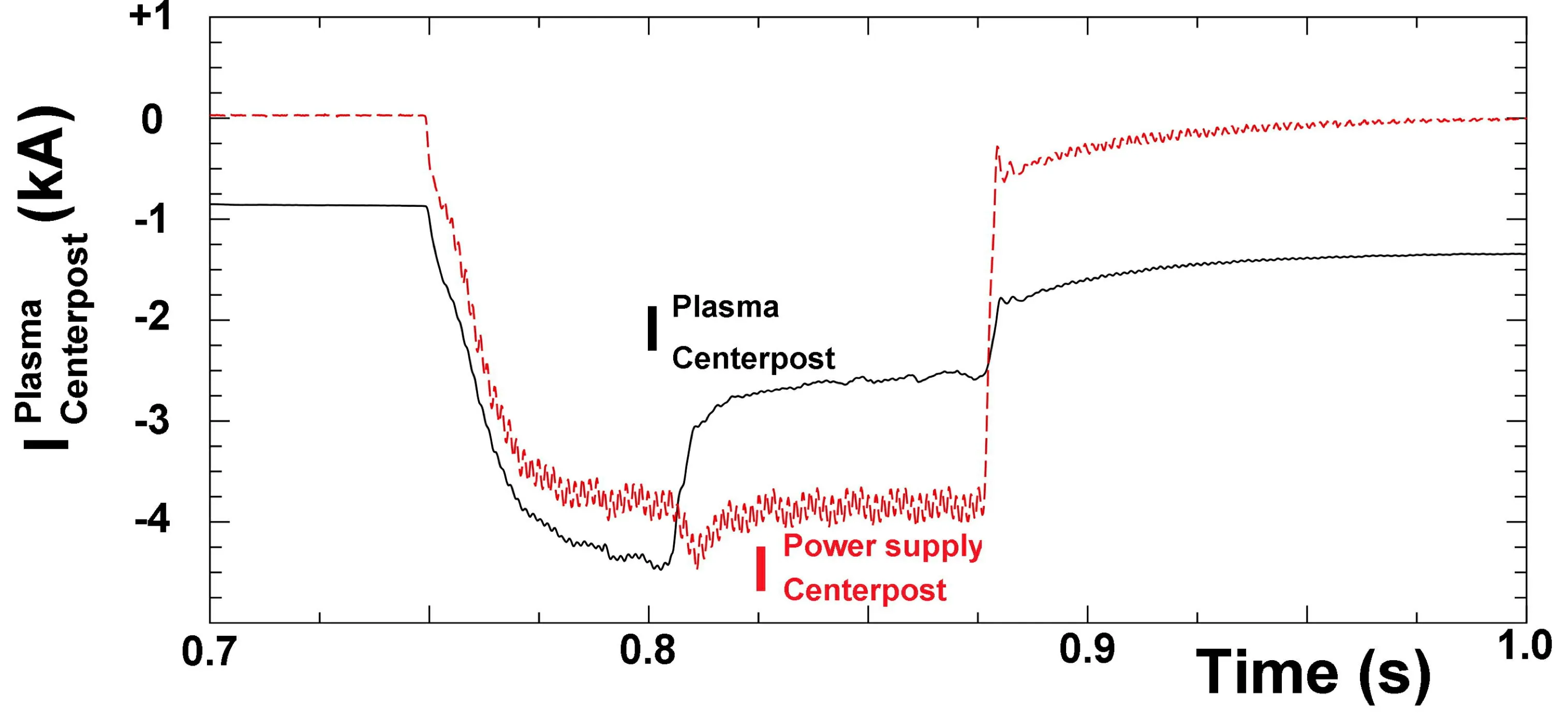
Figure 6.Waveforms of argon centerpost plasma current,evidencing a sudden decrease after the centerpost discharge becomes attached to the aluminium cylindrical vacuum vessel,shot #208.
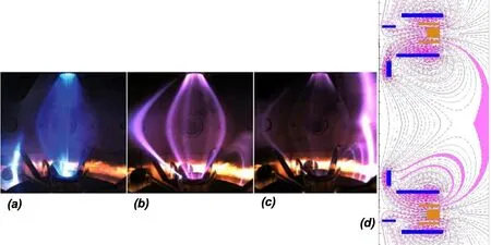
Figure 7.Spurious current path (on the left of the centerpost) in presence of the aluminium vacuum vessel: (a) argon centerpost partially affected,shot #128; (b) hydrogen centerpost seriously affected,shot #78; (c) hydrogen centerpost driven to plasma termination on submillisecond timescale.(d) Maps of magnetic field with spurious current paths being evidenced.

Figure 8.(a) The aluminium vessel being lined on its inner wall,by two,doubly overlapping,2 mm thick polycarbonate cylindrical foils.(b) Similar doubly overlapping polycarbonate foils surround the upper anodic mechanical group.(c) Same for the lower cathodic mechanical group.
After these two last modifications of the electrostatic boundary conditions,the aim of the plasma centerpost for the experimental phase-1 - see figures 11(b) and 12(a) - was obtained in argon in January 2018,with break-down voltage≈ 90 V: the electrode plasma currentICPwas sustained for 1 s at 10 kA while the anode-to-cathode voltage increased to≈ 200 V.
The equatorial diameter of the argon plasma centerpost was 2Rsph≈ 55 cm,as inferred from the edge observed in visible light - see figure 11(b).The equatorial line-averaged electron density <ne> in argon was measured by a commonpath Second-Harmonic-Interferometer (SHI) [24,25] and exhibited an almost linear dependence upon the electrode plasma current: <ne> ∝ICP,with <ne> = 4×10²⁰m-3atICP=10 kA.
As the magnetic field lines start from and end upon electrodes the plasma centerpost temperature cannot be larger than a few eV; it was determined by Langmuir probe measurements only at the edge of the anodic mushroomshaped plasma: the local electron temperature was measured to range from 2 to 8 eV,correspondingly the local electron plasma density ranging fromne= 5×10¹⁹m-3tone= 2×10¹⁹m-3.
Hydrogen as well has no interest for controlled fusion [26],but it is highly indicative of the behaviour of the deuterium that will be used in phase-2 of the experiment.The 10 kA plasma centerpost in hydrogen was also obtained in January 2018,see figures 11(c) and 12(b),its break-down voltage was ≈ 320 V and the electrode plasma currentICPwas sustained for 1 second at 10 kA while the anode-to-cathode voltage decreased to ≈ 220 V.The equatorial diameter of the hydrogen plasma centerpost was 2Rsph≈ 75 cm,larger than in argon plasma,as inferred from the edge observed in visible light - see figure 11(c).The equatorial line-averaged electron density <ne> of the hydrogen plasma centerpost was<ne> ≈ 1.0×10²⁰m-3atICP= 10 kA,lower than in argon plasma.Preliminary results of spectroscopic observations [27]on the plasma equator indicate that in hydrogen discharges the visible spectrum did show only hydrogen lines,whereas the UV spectrum did show limited amounts of metallic impurities; this was presumably due to the fact that the two PF2 mirror coils - see figures 11(b) and (c) - act as effective impurity separators for the plasma (anode,cathode and main plasma).Both argon and hydrogen plasma centerpost discharges were sustained as long as the anode-to-cathode voltage was applied.The much-feared anode arc-anchoring of the plasma [28,29] (i.e.,the discharge concentrating upon a restricted anode spot,and inflicting local damage) never occurred; the explanation resides in the rotation of the plasma centerpost in the azimuthal (toroidal direction),which is evident from the visible light movies collected by a 3600 frames s-1fast camera.

Figure 9.(a) Waveforms of argon centerpost plasma current,evidencing a slow decrease of plasma centerpost current ICP.(b) and (c)Spurious plasma currents with filamentary patterns near the lower PF2 mirror coil.All figures refer to shot #597.
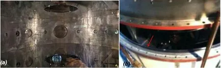
Figure 10.(a) Upper and lower diaphragm glued to the cylindrical large polycarbonate foil with a vacuum compatible strong sealant,able to sustain the diaphragm weight.(b) Polycarbonate insulating spacer ring,vacuum sealed with two o-rings on both sides,inserted between the upper ferrule and the aluminium vessel,sketched also in figure 2(a).

Figure 11.(a) Shaping magnetic field,up/down symmetric,produced by the eight Group-B-PFInt coils,the four upper coils are denominated in this figure,the lower four ones being mirror symmetric across the equatorial plane.(b) Argon centerpost discharge #1037 at ICP =10 kA: pictures from 3 cameras (at different azimuthal angles) are superposed.(c) Hydrogen discharge #1010 at ICP = 10 kA.(d) The electrostatic potential in H discharges at ICP = 10 kA (shown with different colours) is not up/down antisymmetric,i.e.,the plasma charges the Group-B-PFInt coils on the anode side with a different pattern of electric potential with respect to the cathode side.

Figure 12.(a) Argon discharge #1037 at ICP = 10 kA: waveforms of ICP the plasma centerpost current as measured on the power supply and on the return bars of the machine (by Hall sensors) compared with the traces of two in-vessel Rogowski sensors.(b) Hydrogen discharge#1010 at ICP = 10 kA: waveforms of the plasma centerpost current as measured on the power supply and on the return bars of the machine(by Hall sensors) compared with the trace of one in-vessel Rogowski sensor.
The plasma centerpost rotates approximately at an angular frequencyω~ 2π×102rad s-1.The cause of such a rotation appears to be the electrostatic charging of the PF coils casings by the plasma: all the 8 Group-B-PFInt coils inside the vacuum vessel reach different floating electric potentials;figure 11(a) indicates the names of the Group-B-PFInt coils.As previously mentioned,also the top part of the vessel (an AISI304 ferrule-and-lid) and its bottom symmetrical ferruleand-lid were insulated and left floating from the aluminium middle vessel,which was grounded for safety reasons.The PF coils casings were all left floating,as this was the best way to avoid spurious secondary discharges.In hydrogen plasma at 10 kA,the anode (top) was charged to +140 V while the cathode (bottom) only at -80 V,the top ferrule-andlid at +95 V while the bottom ferrule-and-lid at only -55 V,the two PF4 coils (plasma-nozzle-coils) to +50 V on top and only to -10 V on bottom and the PF2 and PF3 coils (mirrorcoils) to +95 V on top and only to -40 V on bottom.TheE×Bdrift of the plasma,that would have been opposite in the anode and cathode region,was therefore not compensated:the top anode has been calculated,by a simple electrostatic code [30],to have the larger electrostatic field,see figure 11(d),and apparently dictated the direction of the net plasma rotation.As the internal magnetic field pointed upwards,while the electrostatic field went downwards,from anode to cathode,the net plasma rotation was clockwise (as seen from the top of the machine).
The aims of phase-1 of the PROTO-SPHERA experiment (10 kA plasma centerpost in hydrogen [1]) had therefore been fulfilled,by introducing a variety of insulating materials.It is remarkable that after the full current argon plasma centerpost was obtained,the hydrogen plasma centerpost was immediately produced and sustained for 1 sec at the full level of 10 kA.
4.First evidences of plasma torus formation and sustainement
Before moving to the final phase-2 of the experiment,the first attempts to obtain the plasma tori were performed already in the first months of 2018.The four magnetic vertical field coils,the PFExt coils,wound around the vacuum chamber as seen in figure 2(b),were fed in series with the Group-B-PFInt internal coil as seen in figure 2(c) with electric currents such that direction of the magnetic field inside the equatorial PFExt coils was opposite to the direction of the magnetic field inside the plasma centerpost discharge,see figure 13(a),but no further modifications were introduced in the machine.The first tori were obtained in argon plasma.The predictive plasma equilibrium [31] calculated under the assumption that the torus does not form,exhibit for the plasma centerpost a single circle of ordinary X-points(Bpol= 0) on equator,as shown in figure 13(a); in the experiment,if the argon centerpost discharge current was produced at low values (ICP~3 kA),the central plasma of figure 13(b)was quite narrow: ~32 cm from symmetry axis and was quite similar to what is calculated in figure 13(a).
If the predictive equilibrium calculation is performed instead under the hypothesis that a plasma torus forms,then a quite different configuration is obtained,exhibiting two circles of ordinary X-points (Bpol= 0) as shown in figure 13(c),one up and the other down the equator,both endowed with magnetic separatrices; in the experiment,if the centerpost discharge current was produced atICP> 5-8 kA,the presence of the separatrices became quite evident,and the shape of the central argon plasma of figure 13(d) was quite broader and quite similar to what is calculated in figure 13(c).
What was found can be summarized by the conclusion that in argon,when the direction of the magnetic field inside the equatorial PFExt coils is opposite to the direction of the magnetic field inside the plasma centerpost discharge,a toroidal configuration is formed and sustained only if the rotational transformof the plasma centerpost (from anode to cathode) is greater than>1/2,which roughly corresponds toICP> 8 kA.The rotational transform is the inverse of the safety factorq; in the discharges illustrated in this paperICP> 8 kA corresponds toqCPlower than 2.This suggests that the torus formation can be attributed to an MHD instability.The safety factor of the plasma centerpost(which is calculated on the limited field lines going from anode to cathode) plays therefore a role analogous to the role of the toroidal safety factor in a standard tokamak (which is calculated on the field lines winding around a toroidal surface).The safety factor of the plasma centerpost is computed through a field line tracing,based on the magnetic fields obtained from the ideal MHD equilibrium code [31]; it is rather insensitive to the assumptions about the pressure profile inside the plasma centerpost,which,by the way,is usually assumed to be a force-free screw pinch.In other words,the dependence ofqCPis almost inverse withICP.

Figure 13.(a) Grad-Shafranov calculation of magnetic field configuration in absence of any closed flux surface current,with ICP = 8 kA value of plasma centerpost current ICP (the value of the current ICP has negligible effects on the calculated centerpost shape),(b) argon shot#1098 at centerpost plasma current ICP = 3 kA,obtained in the magnetic field shown in (a),(c) equilibrium calculation of magnetic field configuration with centerpost plasma current ICP = 8 kA in presence of closed flux surface torus carrying IST = 5 kA,(d) argon shots #1149-1160 (looking at the two opposite sides of the central plasma) obtained in the magnetic field shown in (a).
Immediately also hydrogen plasma tori were obtained carrying toroidal currents up to 5 kA,an example being shown in figure 14(a); they were much better visible than the argon tori,albeit they were extremely “l(fā)ean”,see figure 14(b),as it was expected from predictive magnetic equilibrium calculations that included the PFExt coils effect: the input data of the equilibrium code were the measuredICPand PF coils currents,the toroidal current was adjusted trying to reproduce the external boundary position and the X-points legs.The 4 cm thick aluminium vacuum vessel reacted with skin currents to the penetration inside the machine of the vertical magnetic field produced by the external PFExt coils.The time delay for the full penetration of the vertical field was calculated and measured to be 0.6 s: the plasma tori were therefore produced,applying the anode-cathode voltage just 0.6 s after the PFExt coils were energized,in the purely magnetostatic field,obtained after the skin currents flowing in the aluminium vessel were completely dissipated;the sustainment of the first hydrogen tori was therefore limited to about 1/3 s.It has to be remarked that this time interval is anyway at least one order of magnitude greater than any other characteristic plasma time,including the current diffusion time,and therefore the tori can be considered stationary.The tori were however unexpectedly strongly up/down asymmetric and the power injected into the tori was almost totally discharged into the lower part of the plasma,as shown in figure 14(c).
The tori were always equipped with a “magnetic separatrix”,i.e.,a conical “fan” of plasma able to discharge the power dissipated inside the torus,out of the two circles of ordinary magnetic X-points (Bpol= 0,BT≠ 0).The filamentation of the plasma current,when it entered the lower PF2 internal mirror coil,was very intense,as seen in figure 14(c).
The presence of two magnetic separatrices compels to introduce divertor plates,i.e.,mechanical structures able to withstand the power flowing into the fans.The impact of the plasma on the lower diaphragm,as seen in figure 14(d),shows clearly evidence of the nearly axisymmetric nature of the plasma torus.The lower diaphragm however acted as a divertor plate,but being a polycarbonate sheet,was completely inappropriate for withstanding the power coming out from the lower magnetic separatrix.
Unpleasant effects for the plasma torus are associated with any kind of filamentation of the plasma current: the plasma filaments act as a relevant source of magnetic disturbances to the overall axial symmetry of the magnetic configuration.The two main disturbances from current carrying filaments are: (a) to add a counterflowing current on the outboard edge of the torus and (b) to introduce an ergodic component to the magnetic field inside the torus [32].The results would be that: (a) the filamentation could therefore contrast the helicity injection and (b) the integrity of the magnetic toroidal flux surfaces could be spoiled.Both points could worsen the energy confinement inside the plasma torus in the future phase-2 of the experiment: the first point could decrease the toroidal current in the spherical torusIST,by decreasing the current ratioIST/ICP; the second point could directly enhance the energy losses through an ergodic magnetic field.
In order to move towards the phase-2 of PROTOSPHERA it was decided,at the end of 2018,to operate in 2019-2021 an additional intermediate phase,having the aim of progressively pushing the plasma from the "lean" tori of phase-1 to the spherical tori of phase-2.In order to mend the more relevant insulation problems,which appeared in the first plasma operation,a number of actions were undertaken,which have included a new insulating and transparent cylindrical vacuum vessel,new internal compression coils,new insertable and extractable polycarbonate diaphragms and insulated divertor plates.A following paper will illustrate the intermediate phase of PROTO-SPHERA.

Figure 14.(a) “Lean” torus visible as a brighter belt at the outer edge of the hydrogen plasma centerpost.(b) Same,with superposed predictive equilibrium calculation of magnetic flux surfaces obtained from the measured ICP and PF coils currents trying to reproduce the external boundary position.(c) Lower magnetic separatrix,just below the lower circle of X-points,from a different camera.All three images refer to hydrogen plasma shot #1280.(d) Polycarbonate lower diaphragm,removed at the end of the experimental campaign in which PROTO-SPHERA produced the first plasma tori.
5.Conclusions
The PROTO-SPHERA experiment,by removing the two metal central conductors of the tokamak configuration and by replacing both with two electrodes feeding a plasma centerpost discharge,has overcome the need of a toroidal vacuum vessel for producing a magnetically confined plasma and has substituted it with a cylindrical chamber surrounding a simply connected plasma.The centerpost discharge is able,through magnetic reconnections (DC helicity injection),to form a plasma confining torus and to sustain it in steady state carrying a toroidal current.The greatest difficulty in this new configuration is obviously the possibility that spurious plasma currents flow inside the cylindrical enclosure,but outside the proper centerpost route,along unpredicted and uncontrolled paths,hampering the magnetic configuration,reducing the efficiency by which the plasma centerpost injects magnetic helicity into the torus and finally making the field ergodic inside the torus.
To prevent the spurious plasma current paths,a number of corrections to the boundary conditions of the experiment have been carried out in its initial phase (centerpost only),but are still underway in the intermediate phase (first confined tori).All the electrostatic boundary corrections have introduced insulating materials inside the vacuum vessel in critical places near the plasma.
The corrections have,step by step,not only achieved their desired results,without introducing problems of impurity contamination,but have also shown that the confined plasma tori of PROTO-SPHERA can be sustained in steady state without any need of stabilization by a massive shelllike nearby metal conductor,as it happens in spheromaks [33],since the aluminium START vacuum vessel is very far from the plasma boundary.In any case this point will be definitely clarified by the insertion of the new insulating and transparent cylindrical vacuum vessel.This is also a point of interest for laboratory simulations of astrophysical plasma phenomena,as all the astrophysical plasma events in the cosmos are surrounded,after a given distance,by vacuum and therefore by one among the most effective electrical insulators.
Acknowledgments
The authors would like to thank Antonella De Ninno and Federica Causa for supporting this work and for the helpful discussions.
Appendix: the power supplies
The Group-B-PFInt coils are fed by a DC machine that delivers 2 kA at 350 V DC,built by EEI in Vicenza (Italy),in the years of 2011-2014.A further power supply for the new Group-A-PFInt compression coils will be built in phase-2,as a DC machine able to deliver 1.2 kA at 600 V to the 10 new coils connected in series.
The plasma centerpost power supply,built by EEI as well,is instead limited to the first unit (ICP= 10 kA at 350 V DC,for 1.1 s); a second unit will be built in phase-2,able to increase the electrode plasma current up toICP= 70 kA.
The electrical power supply for heating up the cathode is a six-phased AC machine,also built by EEI,able to deliver 1.7 kA up to 25 V (rms) to the nine tungsten filaments present per phase at this moment; its current capability will be increased to 10 kA per phase in the phase-2 version,where 54 tungsten filaments will be present per phase,in order to increase the centerpost plasma current up toICP= 70 kA.
 Plasma Science and Technology2024年2期
- Plasma Science and Technology的其它文章
- Detection of Al,Mg,Ca,and Zn in copper slag by LIBS combined with calibration curve and PLSR methods
- Experimental study on the effect of H2O and O2 on the degradation of SF6 by pulsed dielectric barrier discharge
- Phase field model for electric-thermal coupled discharge breakdown of polyimide nanocomposites under high frequency electrical stress
- Non-thermal atmospheric-pressure positive pulsating corona discharge in degradation of textile dye Reactive Blue 19 enhanced by Bi2O3 catalyst
- Airfoil friction drag reduction based on grid-type and super-dense array plasma actuators
- Characteristics of laser-induced breakdown spectroscopy of liquid slag