
A study of grid failure mode drivers and methods for accelerated life testing of a 30cm diameter ion thruster
2023-11-19 13:32:42MingmingSUN孫明明JianfeiLONG龍建飛JuanjuanCHEN陳娟娟WeiYANG楊威WeilongGUO郭偉龍andXinweiCHEN陳新偉
Plasma Science and Technology 2023年11期
關(guān)鍵詞:楊威
Mingming SUN (孫明明) ,Jianfei LONG (龍建飛) ,Juanjuan CHEN (陳娟娟) ,Wei YANG (楊威) ,Weilong GUO (郭偉龍) and Xinwei CHEN (陳新偉)
1 Science and Technology on Vacuum Technology and Physics Laboratory,Lanzhou Institute of Physics,Lanzhou 730000,People’s Republic of China
2 School of Fundamental Physics and Mathematical Sciences,Hangzhou Institute for Advanced Study,University of Chinese Academy of Sciences,Hangzhou 310024,People’s Republic of China
3 Gravitational Wave Universe Taiji Laboratory,Hangzhou Institute for Advanced Study,University of Chinese Academy of Sciences,Hangzhou 310024,People’s Republic of China
4 Key Laboratory of Gravitational Wave Precision Measurement of Zhejiang Province,University of Chinese Academy of Sciences,Hangzhou 310024,People’s Republic of China
5 School of Electrical Engineering,Chongqing University of Science and Technology,Chongqing 404100,People’s Republic of China
Abstract In view of the high cost caused by the 1:1 lifetime verification test of ion thrusters,the lifetime acceleration test should be considered.This work uses the PIC-MCC (Particle-in-Cell Monte-Carlo Collision) method to analyze the five failure factors that lead to the failure of the accelerator grid of a 30 cm diameter ion thruster under the working mode of 5 kW.Meanwhile,the acceleration stress levels corresponding to different failure factors are obtained.The results show that background pressure has the highest stress level on the grid’s erosion.The accelerator grid aperture’s mass sputtering rate under the rated vacuum degree(1×10⁻⁴ Pa)of 5 kW work mode is 8.78 times that of the baseline vacuum degree (1×10⁻⁶ Pa),and the mass sputtering rate under worse vacuum degree (5×10⁻³ Pa) is 5.08 times that of 1×10⁻⁴ Pa.Under the influence of the other four failure factors,namely,the voltage of the accelerator grid,upstream plasma density,the screen grid voltage and mass utilization efficiency,the mass sputtering rates of the accelerator grid hole are 2.32,2.67,1.98 and 2.51 times those of the accelerator grid hole under baseline condition,respectively.The ion sputtering results of two 30 cm diameter ion thrusters (both installed with new grids assembly) after working for 1000 h show that the mass sputtering rate of the accelerator grid hole under vacuum conditions of 5×10⁻³ Pa is 4.54 times that under the condition of 1×10⁻⁴ Pa,and the comparison error between simulation results and test results of acceleration stress is about 10%.In the subsequent ion thruster lifetime verification,the working vacuum degree can be adjusted according to the acceleration stress level of background pressure,so as to shorten the test time and reduce the test cost.
Keywords: ion thruster,failure factors,acceleration stress level
1.Introduction
Ion thrusters have been widely used in the field of spacecraft propulsion based on the characteristics of large specific impulse,long life and high efficiency.With the expansion of applications,the working life verification of ion thrusters has become the focus of research [1-3].Taking the current communication,meteorological,reconnaissance and other satellites as examples,the ion thrusters are required to be in orbit for more than 15 years,with a total cumulative operating life of more than 30000 h [4,5].The 1:1 lifetime verification takes at least 5 years to complete the ground demonstration test.Therefore,in terms of financial resources and human resources,a 1:1 lifetime verification test is a huge cost.Moreover,it also seriously restricts the development cycle of ion thrusters.Therefore,the current lifetime verification test cannot meet the needs of the rapid development of spacecraft equipment,and it is necessary to study a new,fast and efficient lifetime evaluation method.The lifetime acceleration test is an effective way to meet the long-life requirements of ion thrusters.
Over the past decade,many studies focused on the sputtering mechanism of the grids and paid attention to the sputtering on the accelerator grid by CEX (charge exchange)ions.Brophy et al [6] studied the failure mechanism and erosion characteristics of a two-grid system of a 30 cm diameter ion thruster.The research results indicated that there are three failure mechanisms to the grids,which are grid shorting failure due to flaking deposited on the screen grid,electron backstreaming failure,and structural failure by pits-andgrooves erosion,respectively.The vacuum chamber pressure increases the flatness of the accelerator grid mass loss,and the accelerator grid current increased from 30 to 42 mA as the tank pressure increased from 2.4×10⁻⁵to 3.4×10⁻⁵Torr.Brophy et al further indicated that the structural failure is not the first failure mechanism for the accelerator grid.Nakano[7] studied the relationship between the electron backstreaming failure of a three-grid system and the extraction current of a grid single hole through modeling,and used the model to simulate and predict the sputtering shape of the accelerator grid aperture when electron backstreaming occurred.Xia et al [8] used the PIC-MCC method to model and study the beam-focusing difference between a two-grid system and a three-grid system.It indicates that the sputtering of CEX ions on the accelerator grid hole is the main cause of the electron backstreaming and eventually the failure of a three-grid system.Zhang et al [9] established a simulation model of a three-grid system,and studied the influence of background pressure on the ion energy distribution and ion current collected at different locations of the accelerator grid and the decelerator grid.Sengupta et al [10] tested and studied the sensitives of the flow rate of the anode,the hollow cathode and the neutralizer of the NSTAR ion thruster to the effects of discharge voltage and beam current,but did not study the effects of working parameters on specific failure modes.Chen et al [11] developed a three-dimensional numerical model by PIC-MCC method to simulate the beam ion acceleration,extraction,CEX generation and hitting processes of a three-grid system.In 2008,Noord et al [12] tested the influence of parameters adjustment on grid wear of NEXT ion thruster.The results showed that when the screen grid voltage was increased from 1021 to 1179 V,the sputtering rate of the accelerator grid apertures reached the maximum.Based on this mass sputtering rate,due to the continuous expansion of the accelerator grid apertures,the negative potential barrier in the center of the grid aperture to prevent the electrons from the plume near-field region to the discharge chamber,will gradually decrease,and eventually lead to the electron backstreaming failure of the accelerator grid.These previous studies have well demonstrated that the grid,especially the accelerator grid,is the core component that affects the life of the ion thruster,and the parameter adjustment test results prove that there are failure factors on the grid life and different acceleration stress levels on the grid lifetime.However,most of the studies have not fully analyzed the multiple factors that cause the failure of the accelerator grid and the stress level of various factors on the erosion of the accelerator grid.
Based on the fact that the accelerator grid is the critical component for a three-grid system,then the key to designing the lifetime acceleration test of the ion thruster is to study the effect of different failure factors on the erosion of the grids,and determine the most important influence factor and its acceleration stress level on the lifetime of the grids.In this work,the PIC-MCC method is used to analyze the effects of different failure factors on a three-grid system of a 30 cm diameter ion thruster(developed by LIP,Lanzhou Institute of Physics)under 5 kW work mode,especially ion sputtering of the accelerator grid.The most important influence factor and its acceleration stress level on the erosion of the grids is determined by calculation,thus providing a reference for the subsequent design of the lifetime acceleration test of ion thrusters,so as to achieve the purpose of greatly reducing the test verification period and the test cost.
2.Failure factors and setting range
The purpose of the lifetime acceleration test is to compress the test time from 5 years to 1 year or less without affecting the verification life cycle.The design steps are as follows.Firstly,according to the failure modes of the grids of the thruster,the multiple failure factors are sorted out,and the most important influence factor is identified.Secondly,on the basis of obtaining the most important influence factor,the acceleration stress level is calculated by numerical simulation.According to previous research results[3-7],the main failure modes of the accelerator grid are electron backstreaming failure,structural failure,and shorting failure due to screen grid erosion.The screen grid erosion is not obvious in the lifetime test of ion thrusters.The life test of the 30 cm diameter ion thruster conducted in LIP showed a slight change in the aperture and thickness of the screen grid after 6500 h of operation[13].The structural failure of the accelerator grid is mainly due to the pits-and-grooves erosion caused by CEX ions sputtering,and the pits-and-grooves erosion around individual apertures will eventually wear through the accelerator grid,resulting in short with the screen grid by thin metal sputtering.However,for a three-grid system,the structural failure is not the first failure mechanism for the accelerator grid [6],and the decelerator grid effectively reduces the pits-and-grooves corrosion caused by CEX ions on the accelerator grid,thus greatly reducing the risk of structural failure of the accelerator grid[7,8].Meanwhile,the accelerator grid hole is enlarged due to CEX ions sputtering,eventually leading to potentials in the center of the grid apertures that are not sufficiently negative to prevent electron backstreaming into the discharge chamber.Therefore,electron backstreaming failure is the main failure mode for a three-grid system,and in this work,only the failure factors that can cause electron backstreaming failure are studied.In addition,it should be noted that although the performance of the thruster will change during the lifetime acceleration test,mechanisms of the different failure modes will not change except to accelerate the sputtering of ions and the failure of the grids,so there are no new failure modes introduced.Meanwhile,the acceleration test should select reasonable test conditions and duration according to the stress level so as to avoid the abnormal operation of thrusters for a long time.
There are many factors that can cause electron backstreaming failure of the accelerator grid[6-14].At present,it can be summarized that the test and the analysis results mainly include background pressure,the diameter of the grid hole,the voltage of the accelerator grid,upstream plasma density,the screen grid voltage,propellant flow rate,mass utilization efficiency,thickness of the accelerator grid and the screen grid,etc.In view of these failure factors,it is necessary to determine the research prerequisite,and carry out equivalent replacement of the failure factors with coupling relationship.First of all,the thruster design is not changed in the analysis,that is,the parameters changed by subjective factors are only used as input boundary conditions.For example,the grid gap is only considered as an input parameter rather than as a failure factor,since the equilibrium hot gap under different powers is a fixed value[14,15].Other parameters,such as the diameter of the grid hole,electric field,and magnetic field,are also used as input boundaries.Secondly,the ion beam anomalies caused by the design defects of grid geometric parameters are not considered,and only the failure caused by normal ion erosion is targeted.Finally,parameters with coupling relationships can be replaced with a single parameter.For example,the plasma density upstream of the grids is affected by the mass flow rate.According to the previous calculation results of the influence of the mass flow rate on the distribution of plasma density [16],the grid erosion caused by the mass flow rate can be converted into the grid erosion caused by upstream plasma density,so as to reduce the number of failure factors.
After analysis and replacement,there are only five failure factors leading to the electron backstreaming failure,which are background pressure,the screen grid voltage,the accelerator grid voltage,upstream plasma density and mass utilization efficiency (referring to that of the discharge chamber),and these parameters have no coupling relationship with each other and are all single factors.Meanwhile,these factors allhave significant effects on the generation of CEX ions.For example,according to the Child-Langmuir equation,the beam voltage,or the screen grid voltage,can change the average beam density,thus affecting the CEX ion density and changing the sputtering rate of the accelerator grid.The variation of the accelerator grid voltage will change the attraction effect of slow CEX ions,thus affecting the sputtering rate.The extraction beam is proportional to the upstream plasma density,and due to the space charge effect,the upstream plasma density will change the focus of the beam and affect the density and distribution of CEX ions.Increasing the background pressure will enhance the density of residual atoms and the probability of charge exchange collision.The mass utilization efficiency affects the amount of xenon atoms escaping from the discharge chamber through the grid holes.With the decrease of the mass utilization efficiency,the production rate of CEX ion will increase accordingly,so its influence mechanism is similar to the background pressure.
On these bases,the PIC-MCC method is used to calculate the acceleration stress levels of the five failure factors and the corresponding influence on the accelerator grid corrosion.Table 1 shows the rated working parameters of the 30 cm diameter ion thruster under 5 kW mode.In the table,the hot gap between the screen grid and the accelerator grid is the measurement results when the thruster reaches thermal balance [17].Since the grid gap can be stabilized within 10 min after the thruster is started,the grid gap is taken as a fixed boundary in the calculation.
The setting points should be selected for different failure factors,and a baseline value is set for comparison of the influence of failure factors.The baseline values are generally selected for conditions that cause low ion sputtering to the grids,and the in-orbit operating conditions can be selected.Then,the rated working condition of the 5 kW mode is compared with it,and the corresponding stress level is calculated as the evaluation basis.In calculation,when one failure factor is changed,the other failure factors remain unchanged.The setting for the failure factors is shown in table 2.It should be noted that the setting points of some failure factors shown in table 2 are far beyond the adjustment range in the actual performance test(the flow rate and voltage adjustment range generally do not exceed ±10% of the rated condition).However,in order to more obviously compare the stress levels of different failure factors,a wider range of parameters is set.

Table 2. Setting of the failure factors.
3.Calculation model
Because the grid apertures are axisymmetric,the twodimensional axisymmetric model can be used to simulate the three-dimensional process of beam extraction,which is shown in figure 1(a).The ions and electrons in the grid acceleration region are treated as charged particles and fluids,respectively.The neutral atoms are also treated as particles.The particle density corresponding to the vacuum degree of the facility is treated as the background neutral density.The PIC method is used to describe the motion of beam ions and CEX ions in the calculation region.The MCC method is used to solve the exchange charge collision process between high-speed beam ions and slow neutral atoms,that is,the generation of CEX ions.As is shown in figure 1(a),the upper,lower and right boundaries of the model are set as Neumann boundaries,that is,=0.It is noted that the left boundary is set as Φ=Vsc+Vp,which means the voltage on the left boundary is the sum of the screen grid voltage and the plasma potential.As is shown in figure 1(b),the upstream of the model is set as the plasma inlet,and the downstream of the model and the surfaces of the three grids are all set as absorb boundary,that is,when the ion moves to these boundaries,the ion information is deleted,and the ion movement is no longer calculated and tracked.The upper and lower boundaries are set as reflect boundary,that is,when the ion moves to these boundaries,the ion is treated by specular reflection and return to the calculation area and re-participate in the calculation.In addition,the upstream ion density shown in table 1 is on the order of 1017m-3,in order to reduce the computational burden of PIC simulation,the number of macroscopic ions ineach time step is entered into the calculation area according to an appropriate ratio of 10000:1 to the calculated ion number.

Table 3. Parameters setting of the calculation model.
Table 3 shows the parameters setting of the calculation model,and the simulated work mode is 5 kW.Wherersc,racandrdelare the radii of the screen grid,the accelerator grid and the decelerator grid respectively,tsc,tacandtdelare the thicknesses of the screen grid,the accelerator grid and the decelerator grid,respectively.ds-aandda-dare the gaps between the screen grid and the accelerator grid,the accelerator grid and the deceleration grid,respectively (the values in the table are measured results).Vsc,VaccandVdelare the voltages of the screen grid,the accelerator grid and the decelerator grid,respectively.Tiis ion temperature which is approximated with the temperature of the discharge chamber[18],Teuis electron temperature upstream of the grids,and the electrons in this region are mainly from ionization in the discharge chamber and emission of the hollow cathode.Tedis electron temperature downstream of the grids,and the electrons in this region are mainly from ionization in the plume region and emission of the neutralizer.Vpis the plasma potential,which is set according to the calculation result of the plasma sheath potential [19].
By ignoring the effect of magnetic fields on the ion beam,the potential can be solved by the Poisson equation,as shown in equation (1),whereε0is the dielectric constant,niandneare ion density and electron density,respectively.
For a two-dimensional axisymmetric model,the Poisson equation can be expressed as equation (2),whererandzare radial and axial coordinates of the mesh grid.When solving the Poisson equation,the whole calculation region is divided into a large number of equally meshed grids,the size of which is smaller than Debye lengthλd.Therefore,the size of the meshed grid is set as 0.025 mm and the time step is set as 1.5×10⁻¹⁰s in the model after calculation (the minimum Debye length is calculated to be 0.029 mm).The finite difference method and Gauss-Seidel iteration are used to solve the Poisson equation to obtain the potential distribution in the calculation region,and the relaxation factor is introduced to optimize the calculation.The electric field intensity at the ion location is solved by linear interpolation.
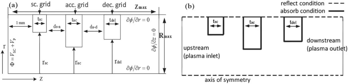
Figure 1.Solution region of the model.(a) Simulation model and (b) boundary setting.
According to the Newton-Lorentz equation for ions,which is given by
whereMis ion mass,viandxiare speed and position of ions,respectively,Eis electric field intensity at the location of the ions.In the model,it is assumed that xenon atom velocity follows the Maxwell distribution,and the atom enters the calculation region from the upstream boundary at thermal velocity.The position and velocity of the atom are updated according to the defined number of cycles.Electrons in the acceleration region are treated as a fluid,whose density follows the Boltzmann distribution,which is shown in equation (4).Whereneis the electron density,?is the potential at the location of electrons,ne,ref,Te,refand?refare the electron density and electron temperature and potential of reference points,respectively.In the calculation of electron density upstream and downstream of the accelerator grid,the reference points are selected in the interior of the discharge chamber and in the neutralization area of the plume [8].
The double charged ions are not considered in the calculation,and the number of ions entering the calculation area from the upstream boundary (which is shown in figure 1) in the unit time step can be expressed as equation(5),whereTeis the electron temperature.It is noted that on the basis of obtaining the time step of each ion and the total time for the beam to reach stability,in each time step,a certain number of ions,ΔN,which enter the calculation region from the left boundary,are accelerated by the grid electric field and extracted from the right boundary.Then,the number of ions extracted from the right boundary and the corresponding calculated value of the beam current is counted in each time step.When the calculated value of the beam current is equal to the designed value of the beam current,it is considered that the extracted beam current reaches the steady state,and the ion density distribution is the result after the time average.
The initial velocity of ions entering the calculation region is set as Bohm velocity,and the initial position of ions entering the calculation region within each time step is random.As is shown in figure 1(a),the initial position of the ion in directionz(axial direction) is 0,the radial direction (rdirection) and the incidence angle of the ion are random numbers.Therefore,the initial position of the ion entering the calculation region can be expressed asr0=,whereranis a random number (generally in the range of 0-1).
In the MCC collision model,elastic collisions between ions and atoms are considered to simulate the charge exchange process.In the unit time stepΔt,the collision probabilityPcan be expressed as equation (6),wherexiandviare the position and velocity of the ion,σis the charge exchange cross section [20],which can be expressed asσ=(k1ln Δv+k2)2×10-20(wherek1andk2are all constant,andΔvis the velocity of ions relative to atoms at the time of collision),nis the atomic density at the location of the collision.
After ignoring the charge exchange process between other neutral particles in the vacuum chamber,such as O2,N2and H2O,and further ignoring the charge exchange process between the Mo atom of the grid and xenon ions [21],it can be considered that the main source of CEX ion is residual xenon atoms in the vacuum chamber and unionized xenon atoms permeating from the discharge chamber to the grids.With the assumption that the residual xenon atomic density is uniformly distributed near the grids,and the xenon atomic number density follows the ideal gas equation,that is,the residual xenon atomic densityn1can be expressed asn1=P/kT(P,Tandkare the pressure,gas temperature and Boltzmann constant,respectively).In the calculation,the xenon gas temperatures in the upstream and downstream of the grids (shown in figure 1(b)) are set to 500 K and 300 K,respectively.The density of unionized xenon atoms permeating into the three grids from the discharge chamber,namelyn2,can be calculated according to the mass utilization efficiency and the number of ions entering the calculation region in each time step by the PIC method.The atomic densityn(xi)shown in equation (6) can be expressed as the sum ofn1andn2,which is shown in equation (7).
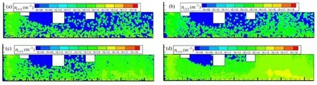
Figure 2.Density and location of CEX ions under different background pressures.(a)1×10⁻⁶ Pa,(b)1×10⁻⁴ Pa,(c)5×10⁻³ Pa and(d)1 × 10⁻² Pa.
In the calculation,the number of xenon ions bombarded to the surface of the accelerator grid hole and the decelerator grid hole is counted,respectively,in each time step,and the sputtering yield of Mo material corresponding to the number of the counted ions is calculated.That is,when a single ion with a particular energy bombards the grid surface,it will produce a certain number of atoms or sputtering,and the unit is n/ ion or g/ ion.The amount of sputtering yield is calculated by the preset number of iterations,and sputtering yield is calculated according to the fitting formula given by Rosenberg,Brophy and Yim et al [22-24].
4.Calculation results and analysis
4.1.Influence of background pressure
The background gas in the vacuum facility is mainly composed of xenon.Because the ion beam contains a large number of high-energy particles,gas discharge can still occur in the near and far fields of the plume,resulting in a large number of CEX ions and etching the grid.In addition,a high vacuum degree will cause the neutral gas to re-flux into the discharge chamber to participate in the discharge,and the ratio of electron re-flux to ion beam is required to be controlled within 1% [25].In this work,a total of eight kinds of background pressure states of 1 × 10⁻⁶Pa (simulating inorbit environment),1×10-5Pa,1×10-4Pa,5×10-4Pa,1×10-3Pa,5×10-3Pa,1×10-3Pa and 5×10⁻²Pa are calculated,respectively.The distributions of beam ions,neutral atoms and CEX ions and the sputtering rate of the grid hole are calculated.As is shown in figure 2,due to the emphasis on ion erosion,only the position and density distribution of CEX ions under background pressure of 1×10⁻⁶Pa(baseline),1×10-4Pa (5 kW rated condition),5×10-3Pa(common condition)and 1×10⁻²Pa(ultimate condition)are given in this paper,and density and position distribution of beam ions are not given.
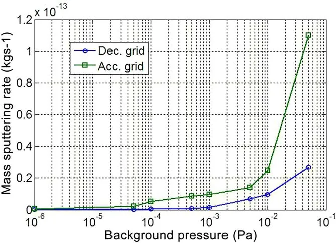
Figure 3.Influence of background pressure on the sputtering rate of the grid hole.
According to the simulation results,with the increase of background pressure,the distribution of beam ions is almost not affected,but the density of CEX ion increases obviously.As is shown in figure 2,the CEX ion density between the screen grid and the accelerator is almost unaffected by background pressure,mainly because most of the CEX ions generated in the region between the screen grid and the accelerator grid are extracted to the region between the accelerator grid and the decelerator grid by the influence of the electric field.Since the main source of CEX ions is residual xenon atoms and unionized xenon atoms,and with the increase of background pressure,the residual atoms near the grids will increase significantly,and the probability of charge exchange collision will also increase.Therefore,the CEX ion density increases most significantly in the downstream regions of the grids.As is shown in figure 2,CEX ions bombarded the surfaces of the accelerator grid and the decelerator grid are mainly generated in the region close to the downstream of the calculation region.The CEX ions generated in this region are also the main source of ion sputtering erosion to the accelerator and decelerator grids.
In the calculation,the mass sputtering rate of CEX ions bombarded to the accelerator grid and the decelerator grid is also counted.Figure 3 shows the relationship between the mass sputtering rate of aperture walls and the background pressure.It is calculated that when the pressures are 5×10⁻³Pa and 1 × 10⁻⁴Pa (5 kW rated condition),the accelerator grid hole sputtering rates are 44.56 times and 8.78 times of that under 1×10⁻⁶Pa (baseline),respectively,and the accelerator grid hole sputtering rate under 5×10⁻³Pa is 5.08 times of that under 1×10⁻⁴Pa.
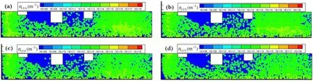
Figure 4.Density and location of CEX ions under different accelerator grid voltages.(a)-100 V,(b)-300 V,(c)-500 V and(d)-700 V.

Figure 5.Influence of accelerator grid voltage on the sputtering rate of the grid hole.
4.2.Influence of the accelerator grid voltage
When other parameters in table 1 remain unchanged and the accelerator grid voltages are adjusted to -100 V,-300 V,-500 V and -700 V,respectively,the simulation results of position and density distribution of CEX ions are shown in figures 4(a)-(d).As is shown in the figure,with the increase of the accelerator grid voltage,the density and location of CEX ions do not change significantly.The density of CEX ions is still in the order of 1013m-3,and most of the CEX ions that can bombard the grids are mainly concentrated in the region between the accelerator grid and the decelerator grid,and the downstream of the decelerator grid.In addition,according to the distribution of beam ions (not given in the paper),the focusing characteristics of beam ions are normal,and no direct sputtering of beam ions on the grid surface occurs.
According to the statistical results of the mass sputtering rate of CEX ions bombarding the accelerator grid and the decelerator grid,figure 5 shows that the mass sputtering rate of the aperture of the accelerator grid changes linearly with the increase of the accelerator grid voltage,while the sputtering rate of the decelerator grid hole is almost not affected by the voltage change.When the accelerator grid voltage is -400 V,the sputtering rate of the accelerator grid hole is 2.72×10⁻¹⁵kg s-1,which is 2.32 times the sputtering rate of the baseline voltage of -100 V (1.17×10⁻¹⁵kg s-1).
4.3.Influence of upstream plasma density
The upstream plasma density has a significant influence on the focusing characteristics of the ion beam [25].When changing this boundary,it is necessary to investigate the change of ion beam focusing.Therefore,under the condition that other parameters in table 1 remain unchanged,the ion beam focusing and location distribution of CEX ions are given when the upstream plasma density of the screen grid is changed from 1×10¹⁷m-3to 8×10¹⁷m-3,as is shown in figures 6(a)-(h).
Figure 6(a)shows that when the upstream plasma density decreases to 1×10¹⁷m-3,the ion beam is over-focused and the intercepted current of the decelerator grid is 3.6×10⁻⁷A,and beam ions will directly bombard the decelerator grid apertures.Figure 6(h) shows that when the upstream plasma density increases to 8 × 10¹⁷m-3,the ion beam is underfocused and beam ions will directly bombard the surface of the accelerator grid.Therefore,when the upstream plasma density is lower than 1 × 10¹⁷m-3or higher than 8 × 10¹⁷m-3,it is not a normal ion sputtering process.In this paper,the acceleration effect of upstream plasma density on ion sputtering is mainly considered in the normal focusing,that is,both under-focusing and over-focusing will not occur.Figure 7 shows the relationship between the mass sputtering rate and upstream plasma density.The calculation results show that when the upstream plasma density is 6×10¹⁷m-3(5 kW rated condition),the sputtering rate of the accelerator grid aperture is 5.74×10⁻¹⁵kg s-1,which is 2.67 times the sputtering rate of the baseline condition of 2×10¹⁷m-3(2.15 × 10⁻¹⁵kg s-1).
4.4.Influence of the screen grid voltage

Figure 6.Beam focusing and location of CEX ions under different upstream plasma densities.(a) 1.0×10¹⁷ m-3,(b) 2.0×10¹⁷ m-3,(c)3.0×10¹⁷ m-3,(d) 4.0×10¹⁷ m-3,(e) 5.0×10¹⁷ m-3,(f) 6.0 × 10¹⁷ m-3,(g) 7.0×10¹⁷ m-3 and (h) 8.0×10¹⁷ m-3.
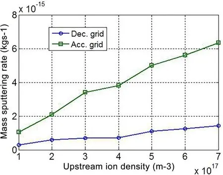
Figure 7.Influence of upstream plasma density on sputtering rate of the grid hole.
The perveance of the grids is proportional to the 3/2 power of the screen grid voltage [25].Therefore,the variation of the screen grid voltage will change the average beam density,and then further affect CEX ion density and the mass sputtering rate of the accelerator grid.Figures 8(a)-(d) show ion beam focusing and location of CEX ions when the screen grid voltage changes from 1200 to 2000 V while other parameters in table 1 remain unchanged.It can be concluded that with the increase of the screen grid voltage,the divergence angle of the ion beam increases gradually.Figure 9 shows that when the screen grid voltage is 2000 V (baseline),the mass sputtering rate of the accelerator grid is 1.98 times that of 1200 V(5 kW rated condition).
4.5.Influence of mass utilization efficiency
With keeping other parameters in table 1 unchanged,figures 10(a)-(d)show the position and density distribution of CEX ions when the mass utilization efficiency decreases from 90% to 60%.According to the analysis results in figure 10,the beam focusing characteristics do not change significantly,while the density of CEX ions gradually increased with the decrease of mass utilization efficiency.Figure 11 shows that for the accelerator grid erosion,the mass sputtering rate at 70% mass utilization efficiency(5 kW rated condition)is 2.51 times higher than that at 90% mass utilization efficiency(baseline).
4.6.Acceleration stress level and test verification
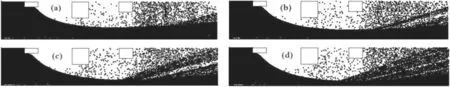
Figure 8.Beam focusing and location of CEX ions under different screen grid voltages.(a)1200 V,(b)1400 V,(c)1800 V and(d)2000 V.
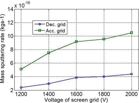
Figure 9. Influence of the screen grid voltage on the sputtering rate of the grid hole.
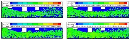
Figure 10.Beam focusing and location of CEX ions under different mass utilization efficiencies.(a) 90%,(b) 80%,(c) 70% and (d) 60%.
According to the above simulation results,the influences of different failure factors on ion sputtering of the grids are summarized.The stress levels of different failure factors of the accelerator grid are shown in table 4.It can be concluded from table 4 that the acceleration stress level is different,but the background pressure has the highest stress level on the accelerator grid erosion.Therefore,background pressure is the most important influence factor.In addition,considering the adjustment of background pressure in the test is convenient,it is recommended that the background pressure can be taken as an influence factor in the lifetime acceleration test first,and other influence factors can be selected according to the test conditions.
At present,the special lifetime acceleration verification of adjusting the background pressure in the vacuum chamber has not been carried out,but the simulation results can be verified through the performance test and life test of a 30 cm diameter ion thruster in different vacuum facilities.From 2017 to 2021,two 30 cm diameter ion thrusters(number M04 and M06,with newly installed grids) were,respectively,subjected to 1500 h and 6500 h verification tests in the vacuum facility numbered TS-7 and TS-7A (as shown in figure 12)of LIP[13,19].The TS-7 vacuum facility is 3.8 m in diameter and 8 m in length,which can provide a vacuum level of 5 × 10⁻³Pa when the thruster is under 5 kW rated condition.The TS-7A vacuum facility has a sub-chamber of 2 m in diameter and 2 m in length,and the main chamber is 4.5 m in diameter and 10 m in length.There are six cryogenic pumps and the total pumping speed is about 260 kl s-1,which can provide a vacuum level close to 1 × 10⁻⁴Pa when the thruster is under 5 kW rated condition.
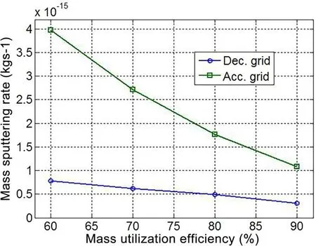
Figure 11. Influence of mass utilization efficiency on the sputtering rate of the grid hole.
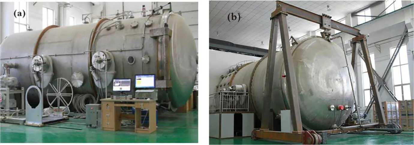
Figure 12.Test facility of 30 cm diameter ion thruster.(a) TS-7 vacuum facility and (b) TS-7A vacuum facility.
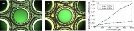
Figure 13.Diameter variation of the accelerator grid hole under different vacuum degrees after 1000 h.(a) Under 1 × 10⁻⁴ Pa,(b) under 5 × 10⁻³ Pa and (c) comparison of variation.
Since the grids of the two thrusters are all newly installed grids,the variation of the accelerator grid aperture within 1000 h is taken to verify the simulation results.The erosions of the accelerator grid apertures in TS-7 and TS-7A within 1000 h test are,respectively,shown in figures 13(a) and (b),and the comparison results of the two diameters’variation are shown in figure 13(c).Equation (7) converts the aperture variation into mass sputtering rate,wherevSis the mass sputtering rate,ρis the material density of Mo,r0andr1are the initial value of the radius of the accelerator grid and the measured radius after 1000 h,respectively.According to equation (7),the mass sputtering rates of the accelerator grid holes at 1×10⁻⁴Pa and 5×10⁻³Pa are 1.97×10⁻¹⁴kg s-1and 8.94×10⁻¹⁴kg s-1,respectively.Therefore,the acceleration stress level of the vacuum degree of 5×10⁻³Pa is 4.54 times that of the vacuum degree of 1×10⁻⁴Pa,which is consistent with the simulation result of 5.08 times.
5.Conclusions
In this work,the acceleration stress levels of five different failure factors are analyzed under 5 kW operation mode for a 30 cm diameter ion thruster.The simulation results indicate that background pressure is the most important influence factor and has the highest stress level for the mass sputtering rate of the accelerator grid apertures,and the experimental results also show that the higher background pressure does lead to faster erosion of the apertures.It is recommended that the background pressure can be taken as an influential factor for the lifetime acceleration test of ion thrusters.But at the same time,it should be noted that high background pressure will cause a higher probability of charge exchange collision and more xenon atoms to backflow into the discharge chamber,which will greatly increase the CEX ion density,and even the thruster is not working properly.The 30 cm diameter ion thruster was previously tested under background pressure of 7 × 10⁻³Pa,where beam interruption and grid breakdown occurred frequently.Therefore,in the design of the acceleration lifetime test,it is suggested that reasonable background pressure and test duration should be selected according to the acceleration stress level,which can fully verify the effectiveness of the influence factor,and the accelerator grid will not fail prematurely within the designed test duration.
Acknowledgments
This work is supported by Key Laboratory Funds for the Science and Technology on Vacuum Technology and Physics Laboratory,Lanzhou Institute of Physics (Nos.HTKJ2022KL510003 and 6142207210303),Independent project of Hangzhou Institute for Advanced Study (No.2022ZZ01009),and Science and Technology Project Affiliated to the Education Department of Chongqing Municipality(No.KJZD-K202101506).
ORCID iDs
猜你喜歡
文萃報(bào)·周二版(2024年12期)2024-04-19 05:06:44
Chinese Physics B(2022年8期)2022-08-31 09:55:36
河南科技(2022年9期)2022-05-31 00:42:40
Chinese Physics B(2021年5期)2021-05-24 02:22:40
商周刊(2018年16期)2018-08-14 01:51:42
小小說(shuō)大世界(2016年8期)2016-05-14 10:42:22
鐵軍(2014年6期)2014-06-03 00:11:09
女性天地(2012年1期)2012-04-29 00:44:03
民間文學(xué)(2009年6期)2009-07-07 09:52:56
高中生·青春勵(lì)志(2008年11期)2008-11-17 10:47:04
 Plasma Science and Technology2023年11期
- Plasma Science and Technology的其它文章
- High-order field theory and a weak Euler-Lagrange-Barut equation for classical relativistic particle-field systems
- Design of new resonant magnetic perturbation coils on the J-TEXT tokamak
- Non-invasive optical characterization and estimation of Zn porosity in gas tungsten arc welding of Fe-Al joints using CR model and OES measurements
- Research on degradation mechanism of trichlorobenzene and Hg0 by nonthermal plasma catalysis
- Ionization wave propagation and cathode sheath formation due to surface dielectricbarrier discharge sustained in pulsed mode
- Development of an atmospheric fluorocarbon plasma jet generated by pulse modulated microwave discharge