
Investigation of electron cyclotron wave absorption and current drive in CFETR hybrid scenario plasmas
2023-10-08 08:20:36HanlinWANG王瀚林XiaojieWANG王曉潔ChaoZHANG張超YunyingTANG湯允迎andFukunLIU劉甫坤
Plasma Science and Technology 2023年9期
關(guān)鍵詞:張超
Hanlin WANG(王瀚林),Xiaojie WANG(王曉潔),Chao ZHANG(張超),Yunying TANG(湯允迎) and Fukun LIU(劉甫坤)
1 Institute of Plasma Physics,Chinese Academy of Sciences,Hefei 230031,People’s Republic of China
2 University of Science and Technology of China,Hefei 230026,People’s Republic of China
Abstract The investigation of electron cyclotron(EC) wave absorption and current drive has been performed for the China Fusion Engineering Test Reactor(CFETR) hybrid scenarios using the TORAY code.To achieve the physics goal of the EC system in CFETR,a total of four wave frequency values and nine locations of launching antennas have been considered,and the injection poloidal and toroidal angles have been scanned systematically.The electron cyclotron current drive(ECCD)efficiency of the 170 GHz EC system is quite low due to the wave-particle interactions being located at the low-field side.To optimize the ECCD efficiency,the wave frequency is increased up to 221-250 GHz,which leads to the power being deposited at the high-field side.The off-axis ECCD efficiency can be significantly enhanced by launching EC waves from the top window and injecting them towards the high-field side.The optimized ECCD efficiency at ρ=0.32 and at ρ=0.4 is 2.9 and 2.2 times that of 170 GHz,respectively.
Keywords: current drive,ECCD efficiency,CFETR
1.Introduction
The China Fusion Engineering Test Reactor(CFETR) is a next generation device in the roadmap of China’s magnetic confinement fusion energy development,which is targeted at bridging the gap between ITER and the first commercial fusion power plant [1].In the early conceptual design of CFETR,the device parameters wereR/a=5.7/1.6 andB0=5 T(named phase I in the literature) [2].In the latest design,to achieve long-pulse operation with GW-level fusion power,the size and magnetic field of the device have been increased and set atR/a=7.2/2.2 andB0=6.5 T,respectively,and a hybrid scenario has been developed using integrated simulations [3].Compared to steady-state operation,hybrid operation has higher internal inductance and plasma currents as well as lowerβNand Greenwald density.
Electron cyclotron resonance heating(ECRH) [4-7] and electron cyclotron current drive(ECCD) [8-11] are the two effects produced by the interaction between electromagnetic waves in the electron cyclotron(EC) frequency or its low harmonics with plasma.EC systems possess a number of attractive technological features.First,since electron cyclotron waves(ECWs) propagate in a vacuum,the EC launcher can be placed distant from the plasma.Second,the power deposition can be flexibly controlled by the toroidal magnetic field,wave frequency and antenna steering angle.Third,the physics mechanism by which ECW interacts with plasma is simple,and the coupling is insensitive to the conditions at the plasma boundary.Fourth,the interaction of ECW with the plasma edge is negligible,so there is no additional impurity release.Furthermore,a reliable high-power source can be obtained.
ECRH/ECCD is a well-established and widely used scheme for plasma localized heating and non-inductivecurrent drive in tokamak fusion reactors.It can be used for start-up assistance,plasma heating,off-axis current drive and magnetohydrodynamic(MHD) instability suppression.In 2015,the conceptual design of an EC system on a small CFETR was proposed,and a 20 MW 170 GHz EC launcher was designed to be installed on the equatorial window[12].In 2018,the performance of ECRH/ECCD at three EC antenna positions(top,low-field side(LFS) and mid-plane launcher)in the flattop and ramp-up phase was studied in the steadystate operation of CFETR phase I [13].In 2019,the ECCD characteristics of equatorial and top port launchers in CFETR phase I plasma with a flat density profile were evaluated,and the current drive for the equatorial port launcher at different wave frequencies was simulated in a relatively low electron temperature plasma of CFETR phase II [14].After iterative design between physics and engineering research,CFETR hybrid scenario was proposed [3].The main task of the EC system was identified as the application of off-axis heating and current drives(H&CD) to improve confinement and MHD performance.Based on to the physical integrated simulation of the CFETR baseline hybrid scenario,the EC system was designed to drive 800 kA and 460 kA current at normalized plasma radiusρ=0.32 andρ=0.4,respectively,to provide modification of theqprofile,and to apply 130 kA drive current for neoclassical tearing mode(NTM)suppression nearq=2(ρ=0.51).
In the engineering design,36 MW EC power needs to be injected into the plasma through three top launchers[15],and 18 transmission lines and a pair of focusing mirrors and steering mirrors needs to be installed in the pipeline of two of the three top windows.In addition,shielding blocks are required inside the pipeline to protect the components from neutron irradiation [16].It is a huge challenge for the EC system design to achieve high-power injection in a limited space.On the other hand,the CFETR blanket is penetrated by the EC system and the tritium breeding ratio(TBR) is hence reduced.In order to make sure that TBR>1.1 and achieve tritium self-sufficiency,the port size needs to be minimized.
In order to meet the above requirements and constraints,the performance of ECW absorption and current drive in CFETR hybrid scenario plasmas is investigated in this study,and the balance between ECCD efficiency and engineering feasibility is considered.The paper is organized as follows.Section 2 describes the main parameters of CFETR hybrid plasma and the setup of the EC system.The simulation results and discussion of ECCD performance at 170 GHz are presented in section 3.The optimization of current drive by depositing ECW at the high-field side(HFS) is addressed in section 4.Finally,a conclusion is given in section 5.
2.EC interactions in CFETR hybrid scenario plasma
2.1.CFETR hybrid scenario
In the analysis presented in this paper,the CFETR baseline hybrid scenario [3] has been considered.The main plasma parameters are as follows: major radiusR0=7.2 m,minor radiusa=2.2 m,plasma currentIP=13 MA and the vacuum toroidal magnetic field in the center isB0=6.5 T.The equilibrium of the CFETR hybrid scenario is constructed as per an EFIT code [17].All simulations are based on the electron density and temperature profiles of the CFETR hybrid baseline scenario,as shown in figure 1.The central electron densityne0=1.28×10²⁰m-3,the central electron temperatureTe0=30.48 keV and the effective charge numberZeff≈2.5.Here,ρis the normalized plasma radius,which is the square root of the normalized toroidal magnetic flux.
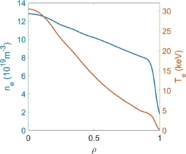
Figure 1.Electron density(blue)and temperature(red)profiles of the CFETR baseline hybrid scenario.
2.2.EC resonances in CFETR
In this paper,the following four wave frequencies are investigated,namelyf=170,210,221 and 250 GHz.The relationship between wave frequency and toroidal magnetic field satisfies
wherefis the ECW frequency,nis the electron harmonic number andBtis the magnetic field of EC resonance.According to equation(1),the fundamental harmonic ordinary mode(O1-mode) is mainly considered in this study.
The major radius of EC cold resonance is located atRce=28nR0(m)B0(T)/f(GHz).It can be observed that the radial region where the ECW interacts with the plasma is related to the ECW frequency and the magnetic field.Figure 2 provides a clear view of the relationship betweenRcewithB0for the four frequency values,and for the first and second harmonics.Here,the O2-mode refers to the second harmonic ordinary mode.In general,plasmas interact with ECW in EC frequency or its low harmonics,and the EC power may be absorbed before reaching the cold resonance in the case of LFS injection,especially in high electron temperatures plasmas.SinceB0is set at 6.5 T,the following conclusion can be reached.For 170 GHz,the first harmonic interaction occurs at the LFS,thus resulting in a lower ECCD efficiency due to trapped particle effects.For 210,221 and 250 GHz,theinteraction of the first harmonic occurs at the HFS,and the ECW can drive significantly higher currents at off-axis locations as a result of fewer collisions and trapped electrons.

Figure 2.Magnetic field B0 versus the major radius of EC cold resonance Rce for ECW frequencies f=170,210,221 and 250 GHz.Horizontal black dashed line denotes the radius of vessel center R0=7.2 m.Upper and lower horizontal blue dashed lines are the radii locations of the last closed flux surface for the LFS and HFS,respectively.
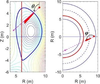
Figure 3.Definitions of poloidal angle(left) and toroidal angle(right) of ECW.Red solid lines correspond to the CRL,the pink dashed lines to the ECW incident path and the blue dashed line to the magnetic axis.Contour lines in the left diagram are the plasma equilibrium shape,the blue solid lines in the right diagram are the last closed flux surface.Red solid semi-circle is the position of the launching point.
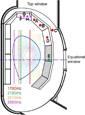
Figure 4.Candidate launching points and frequencies studied in CFETR hybrid scenario plasmas.Inner vertical lines denote the first harmonic CRL for ECW frequencies of 170(red),210(green),221(yellow) and 250 GHz(magenta).Contour lines are the magnetic equilibrium for CFETR hybrid scenario plasmas.
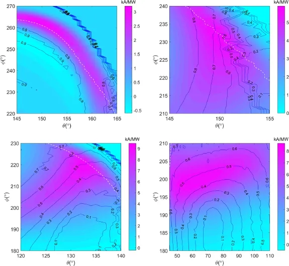
Figure 5.EC-driven current(color scale)and the radial location of current density peak(blue contour lines)as a function of the poloidal angle and toroidal angle,for f=170 GHz.White dashed line delimits the region in which power absorption is larger than 95%.Figures(a),(b),(c)and(d) refer to the launching points A,B,C and E,respectively.

Figure 6.Maximum EC-driven current per unit power versus normalized radius ρ for the candidate launching points,obtained by means of a scan of the poloidal and toroidal angles,for power absorption larger than 95%.Figures(a),(b),(c) and(d) refer to the results of ECW frequencies of 170,210,221 and 250 GHz,respectively.
Although the cold resonance layer(CRL) of the second harmonic forf=250 GHz is located outside the plasma(R=10.48 m),the second harmonic absorption may occur in the plasma and affect the ECCD efficiency due to the downshift resonance absorption effect [18] in the high electron temperature of CFETR hybrid scenarios.Therefore, ordinary mode absorption at the second harmonic might also be considered at high wave frequencies.The cut-off density is about 3.6×10²⁰m-3for 170 GHz,and the other three frequencies have higher cut-off density.Hence,the refraction effect does not play a major role except at large incident angle near the plasma boundary.
The ray tracing code TORAY [19] is used to carry out the calculations of ECRH/ECCD performance in this study.TORAY code is a quasi-optical ray tracing code for EC Gaussian beam propagation.The power absorption is computed by solving the dispersion relation of ECW including momentum conservation in electron-electron collisions,while the current drive is computed by the adjoint approach reworked by Lin-Liu [20].The TORAY code has been successively benchmarked with other EC codes for ECCD in ITER [21].
2.3.EC system setup
The EC system consists of RF sources,transmission lines,EC launchers and auxiliary subsystems,such as high-voltage power supply and water cooling.The microwave source consists of at least 36 gyrotrons each with 1 MW output power.Each EC launcher mainly consists of a pair of focusing mirrors and steering mirrors.The launcher can change the location of EC power deposition by adjusting the incident angles of the steering mirror to achieve the desired physical objectives at different magnetic surfaces.The definitions of ECW incident angles are shown as figure 3.The poloidal angleθis the angle between the vertical positive direction and EC rays,and the toroidal angle φ is the angle between the major radius positive direction and EC rays.It should be noted that φ=180°corresponds to the case where EC wave injection is perpendicular to the magnetic field,and in this case,there is no ECCD [18,22].The poloidal angleθand toroidal angle φ are in units of degree.In the engineering design,two EC launchers are designed for off-axis ECCD and one EC launcher for NTM control.
In consideration of TBR requirements and engineering constraints,five launching points(A-E) are selected for simulations of 170 GHz ECW,as shown in figure 4,where launching point E is located in the equatorial window and launching points A-D are located in the top window.In addition,four launching points in the top window(F-I) are considered for ECCD simulation at higher ECW frequencies.The locations of these candidate launching points are listed in table 1.
3.ECCD at 170 GHz
The investigation of EC power deposition and current drive performance requires a wide scan among ECW frequency,launching position,poloidal angle and toroidal angle.Based on the technical availability of the gyrotron,the frequency chosen for simulation in this section is 170 GHz.Numerical simulations have been carried out by scanning the injection angles for launching positions A-E atf=170 GHz.The ECdriven current per unit power is shown in figure 5 as a function of the injection angles,together with the contours ofthe radial location of the current density peak for the launching points A,B,C and E.The ECCD performance of launching points C and D is similar.Hence,the result for launching point D is not presented in figure 5.The region under the white dashed line indicates that the power absorption is larger than 95%.
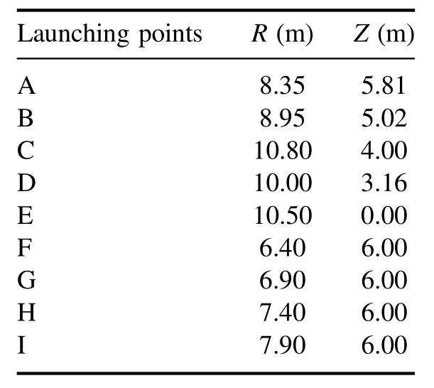
Table 1.Locations of candidate launching points.
According to the results in figure 5,it is possible to maximize the driven current on a specific magnetic surface by selecting the injection angle appropriately.Overall,the maximum ECCD for launching points A and B are located in the far off-axis,while the maximum ECCD for launching points C and E are located in the middle radius.The ECW launched from launching points C and E allow a larger range of power deposition locations,and the driven current decreases as the deposition location changes from middle off-axis to the plasma center.For the launching point A,it is hard to drive current near the magnetic axis.
The results of the driven current and corresponding power absorption for various radial locations are listed in table 2.IEC/PECis the total driven current per unit power in units of kA/MW,γECis the ECCD efficiency in 1020A/(m2W),Pabsis the power absorption coefficient in W/W,jEC/PECis the drive current density per unit power in kA/(m2MW),and Δρis the half-profile width at 1/e of the current density peak.The widely used definition of ECCD efficiency in the literature is,
whereneis the electron density andPECis the incident power of ECW.The maximization ofγECis the ultimate goal of the current drive system in a reactor.
TheIEC/PECin row 2 is the maximum current obtained by scanning the toroidal and poloidal angles of each launching point.The values in rows 3-6 are the ECCD efficiency,injection angles,radial location of current density peak and power absorption coefficient corresponding to row 2,respectively.The values ofIEC/PECmaxima for points C and D are approximate,as are the deposition locationρa(bǔ)nd the power absorption coefficientPabs.This is due to the fact that the launching points C and D are geometrically almost in a straight line with respect to the magnetic axis.It can be observed that the maximum currents for the five launching points are located in the far off-axis.One reason is that the CRL of 170 GHz is located at the LFS,as can be seen in figure 2.Another reason is that the deposition location is moved more outwards due to the Doppler shifted effect caused by the large toroidal angle.
The driven currents in rows 8 and 14 are the maximum currents nearρ=0.32 andρ=0.4,respectively,which are selected by scanning the injection angles.The values in rows 9-12 and 15-18 are the ECCD efficiency,injection angles,drive current density and power absorption coefficient corresponding to the maximum currents,respectively.It is found that the launching point C(atθ=132°and φ=209°)and D(atθ=133° and φ=218°) are the optimal settings for ECCD atρ=0.32 andρ=0.4,respectively.In addition,the ECCD efficiencies atρ=0.32 for launching points C,D and E are approximate,and the ECCD efficiencies atρ=0.4 for launching points C and D are approximate.
To meet the requirement of NTM control,the maximum driven current(in row 21) with the current density peak located atρ=0.51 and profile width Δρ≤0.05 is selected by scanning the ECW injection angles.Here,the profile width Δρ≤0.05 is chosen based on the simulations of NTM evolution studied by the MHD task force.As the deposition width increases,the current required to stabilize the magnetic island increases.However,the EC power available for NTM control is limited.The values in rows 22-26 are the ECCD efficiency,injection angles,drive current density and power absorption coefficient corresponding to row 21,respectively.Note that the minimized profile widths in row 20 of launching points A and B are larger than 0.05,which indicates that these two launching points are not suitable for NTM control whenthe wave frequency is 170 GHz.The maximum currents for launching points C and D are approximate.Based on the above results,point C is selected as the launching point for ECCD and NTM control of the 170 GHz EC system,considering the engineering accessibility and the functional expansion of core heating.
4.ECCD at higher frequency
The ECCD efficiency of the CFETR hybrid scenario at 170 GHz is quite low.The main reason is that the interaction occurs in the LFS,where the impact of trapped particles is large.To optimize the ECCD efficiency,the EC interaction should occur at the HFS by increasing the wave frequency,as mentioned in section 2.2.Therefore,the power absorption and current drive performance have been evaluated by scanning injection angles and launching positions for 210,221 and 250 GHz,respectively.Each case yields a result,as shown in figure 5,hence there are a large number of figures.To get a clear view of the ECCD performance from these results,the driven current per unit powerIEC/PECobtained by scanning the whole range of injection angles under consideration is plotted versus the normalized radiusρ(at the radial location of the current density peak),as shown in figure 6.Each curve represents the maximum current that can be driven at a given normalized radiusρfor a specific frequency and launching point.Note that the maximum current is chosen from the driven current that corresponds to at least 95% power absorption.
The results of 170 GHz are also plotted in figure 6 for comparison.Forf=170 GHz,the maximum driven current for profile tailoring or NTM stabilization is less than 10 kA MW-1,as discussed in section 3.It can be observed that the driven current is lower at the plasma center than midradius for launching points C,D and E.The ECCD efficiency is usually greater in the core plasma due to the higher temperature and smaller fraction of trapped particles.However,the CRL is located at the off-axis of the LFS,as shown in figure 2.This means that the ECW is difficult to deposit at the plasma center.On the other hand,the deposition radial location increases with the increase of toroidal angle,as shown in figures 5(c) and(d).Hence,the driven current at mid-radius for launching points C,D and E is higher than that at the core,because the current profile of a larger toroidal angle is broadened by the Doppler shift.This behavior is consistent with the studies of ECCD efficiency on JET [23].

Table 2.Parameters relevant to the different launching points for ECCD applications.
Forf=210 GHz,the ECCD results of launching points A,C and E are presented in figure 6(b).The launching points F-I are located too close to the CRL,which results in lower ECCD efficiency than that of launching point A for the plasma region of interest.The radial region that is available for ECCD is clearly visible in the plot.The lower limit is close to the plasma center in all the cases,while the upper limit of launching point C is close toρ=0.7,and those of the others are more outwards.In the radial range ofρ<0.2,the maximum driven current can be reached by means of a suitable choice of the injection angles for launching from the mid-plane.At the radial location close toρ=0.3,the launching point C is the optimized choice for ECCD among the candidate launching points.In the plasma region ofρ>0.45,the launching point A is slightly better for driven current.The maximum driven current is 18.56 kA MW-1,close toρ=0.32 and 16.35 kA MW-1close toρ=0.4,as listed in table 3.For NTM control,after selecting the results that satisfy the requirement of profile width Δρ≤0.05,the maximum current is 11.22 kA MW-1,close toρ=0.51.The driven current in the plasma core is slightly lower than offaxis for launching points C and E.The CRL off=210 GHz is located at the mid-radius of the HFS.The EC waves deposited at the HFS can interact with higher-energy electrons,the low collision rate results in higher ECCD efficiency nearρ=0.3.In addition,it is found that launching point A has a significant minimum value atρ=0.38,but is close to the peak value atρ=0.42.The reasons are as follows.The maximum current atρ=0.38 is 8.7 kA MW-1,which is obtained by aiming atθ=152°and φ=212°.However,the maximum current atρ=0.42 is reached by setting the injection angle close toθ=144° and φ=238°.Even the radial position ofρ=0.38 is close toρ=0.42.However,the toroidal angles of these two situations are quite different.In general,a larger toroidal angle results in higher ECCD efficiency due to the current profile being broadened by the Doppler shift.The reason is essentially that the deposition location is sensitive to the injection angle when the top launching point is close to the CRL.The same behavior can be found in the case of launching points A and I atf=221 GHz,which is due to the same reason.
Forf=221 GHz,almost all the radial range is covered for ECW launched from points B,C and E,while the radial range of launching point I is 0.18≤ρ≤0.97.In the radial range ofρ<0.2,the maximum current is driven by launching from the mid-plane.In the radial range of 0.2<ρ≤0.3,launching point C is able to provide a larger driven current.Point B is the optimal launching position for ECCD in the range of 0.34≤ρ<0.45.The ECW launched from the top is good at driven current in the region ofρ≥0.45.It can be observed that,as the envelope of the maximum current moves from plasma core to the edge,the launching point corresponding to the maximum current moves from mid-plane to the top.The maximum driven current is 20.07 kA MW-1close toρ=0.32 and 19.27 kA MW-1close toρ=0.4.For NTM control,the maximum current is 15.21 kA MW-1close toρ=0.51.
Forf=250 GHz,the driven current is plotted versus the normalized radiusρfor seven launching point positions.Overall,the EC waves launched from the LFS or mid-plane isgood at driving current near the magnetic axis,while the ECW launched from the top is good for tailoring the current profiles and active control of NTM.Note that the current in the range of 0.4<ρ<0.7 driven by ECW launched from the top is about 1.3 times that of the mid-plane.This is because the ECW is partially absorbed by the second harmonic interaction at the LFS before it reached the CRL of the first harmonic when EC power is launched from the midplane.The maximum driven current is 21.04 kA MW-1close toρ=0.32 and 18.32 kA MW-1close toρ=0.4.For NTM control,the maximum current is 14.65 kA MW-1close toρ=0.51.For launching points C and E,the current is higher at the core.One reason is the higher temperature and fewer trapped particles in the plasma center.Another reason is that the second harmonic absorption occurs in the LFS,which reduces the EC power available for the fundamental harmonic,when the wave is incident from launching points C or E.For the case of launching point E,the maximum currents atρ=0.44,0.45 and 0.46 are 13.71,4.25 and 13.18 kA MW-1,respectively.The driven current atρ=0.45 is much smaller than the adjacent values.The reason is that the maximum driven current atρ=0.45 is reached by settingθ=70° and φ=204°,which is far away from the region of the maximum driven current atρ=0.44(θ=89°and φ=205°)and 0.46(θ=88° and φ=204°).This is because the value of the deposition location of the region close toθ=88° and φ=204° is not continual after the rounding-off method.
The maximum ECCD efficiency as a function of the ECW frequency for different launching points is shown in figure 7 for the radial positions atρ=0.32 andρ=0.4.Note that the top launching point A is too close to the CRL off=170 GHz,and the low-power absorption coefficient(less than 65%) in the radial range ofρ=0.32-0.51 is one of the reasons for the low ECCD efficiency.Similarly,the ECCD efficiency of launching point B at 170 GHz and launching point F at 250 GHz is slightly lower relative to the other launching points.
Figure 7 provides the following information.(1)Overall,the ECCD efficiency exhibits a saturation setting in a wave frequency of 221-250 GHz.(2) The maximum ECCD efficiency atρ=0.32 is reached by launching ECW of 250 GHz from point A,which is almost 2.9 times the maximum of 170 GHz.(3) The maximum current atρ=0.4 is driven by launching ECW of 221 GHz from point B,which is about 2.2 times the maximum of 170 GHz.(4) When the wave frequency is 250 GHz,the ECCD efficiencies for toplaunching points A and I are slightly higher than those of the LFS outside launching point C and mid-plane launching point E.This is because the second harmonic absorption at the LFS reduces the EC power available for the fundamental harmonic when the wave is incident from launching points C or E.(5)The maximum ECCD efficiency atρ=0.32 forf=221 GHz is 0.185,which is close to the maximum ECCD efficiencyγEC=0.194 forf=250 GHz.This means that 221 GHz provides a compromise to achieve higher ECCD efficiency by using a lower frequency.

Figure 7.Wave frequency f versus the maximum ECCD efficiency of the candidate launching points.Figures(a) and(b) refer to the radial positions ρ=0.32 and ρ=0.4,respectively.

Figure 8.ECW frequency versus EC-driven current,obtained by selecting the maximum current among the cases that satisfy the requirement of NTM control for the candidates’ launching points.
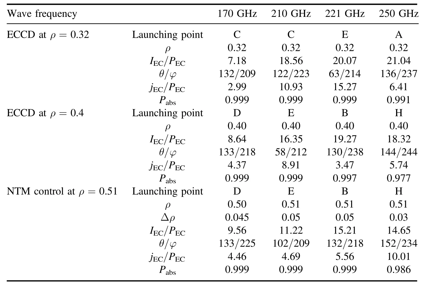
Table 3.Parameters relevant to the different launching points for ECCD applications.
To minimize the window size of the tritium breeding blanket penetrated by the EC system means that the toroidal angle is as small as possible.From the injection angles of row 5 and row 11 in table 3,the toroidal angles corresponding to the top launching points A,B and H are relatively larger(φ>235°).Considering the balance between ECCD efficiency,engineering achievability and TBR requirements,the 221 GHz ECW launched from point E is preferable for off-axis current drive in CFETR hybrid scenario plasmas.
The maximum NTM control current for the candidates’launching points is a function of ECW frequency,as shown in figure 8.In the results carried out by scanning the injection angles,the half-profile widths of launching points B,C,D and E are larger than 0.05 atf=250 GHz.This means that these launching points do not meet the requirements of NMT control at any injection angles.Similarly,launching points A and B are not able to stabilize the NTM,whenf=170 GHz.
From figure 8,the following general conclusion can be drawn.(1) The maximum current for NTM control is driven by injecting ECW of 221 GHz from point B.The current of 15.21 kA MW-1is driven by aiming the injection angle toθ=132°and φ=218°,as listed in column 5 and row 18 oftable 3.(2) Forf=250 GHz,only the top launching points(A and F-I) appear in the figure.This is because the deposition widths of the mid-plane launching point E and the outside launching point C cannot meet the requirement of NTM control.(3) The maximum NTM control current of launching point C forf=221 GHz is 15.01 kA MW-1.It is close to that of launching point B,but with a lower toroidal angle φ=203°(the corresponding poloidal angleθ=107°).Therefore,to maximize the driven current under engineering restrictions,the 221 GHz ECW launched from point C is the optimal design for NTM control in CFETR hybrid scenario plasmas.
5.Conclusion
To achieve the hybrid operating scenario of CFETR,the EC system needs to meet the physical goal of off-axis current drive.To provide a theoretical basis for the design of the EC antenna system,ECW absorption and current drive performance has been evaluated in CFETR hybrid scenario plasmas.A total of four wave frequency values(170,210,221 and 250 GHz) and nine launching points(include the equatorial and top window) have been considered.To cover the whole radial region,the injection poloidal and toroidal angles have been scanned systematically.
For a 170 GHz EC system,launching point C is chosen for off-axis ECCD and NTM control,and this design takes core heating into account as well.To optimize the ECCD efficiency,the wave frequency is increased up to 221-250 GHz.It is found that the off-axis ECCD efficiency can be significantly enhanced by launching high-frequency ECW from the top window and injecting it towards the HFS.The optimized ECCD efficiencies atρ=0.32 and atρ=0.4 are 2.9 and 2.2 times that of 170 GHz,respectively.
Considering the maximization of driven current and TBR,the optimal EC antenna design scheme is as follows:select the launching point E with 221 GHz ECW for off-axis current drive; inject 221 GHz ECW into the plasma from launching point C for NTM control.However,since the technique for high-frequency gyrotrons still needs to be developed,the frequency of the EC system concept design is chosen to be 170 GHz.Since the low ECCD efficiency of 170 GHz atB0=6.5 T,decreasing the toroidal magnetic field may be a potential strategy.The same ECCD efficiency can still be obtained at 170 GHz,with the same plasma equilibrium andqprofile except that theB0is reduced to(170/221)×6.5 T=5 T.
Acknowledgments
The authors gratefully acknowledge the work of the TORAY development teams,and Hanlin Wang thanks Dr Jiale Chen and Xiaojing Wang for fruitful discussions about the physics targets of the EC system.This study is supported by the National Key R&D Program of China(Nos.2017YFE0300500 and 2017YFE0300503) and the Comprehensive Research Facility for Fusion Technology Program of China(No.2018-000052-73-01-001228).
猜你喜歡
當(dāng)代美術(shù)家(2023年4期)2023-08-04 23:34:30
散文百家(2021年11期)2021-11-12 03:06:38
中學(xué)生英語·中考指導(dǎo)版(2021年12期)2021-09-27 09:20:45
中學(xué)生英語·中考指導(dǎo)版(2021年1期)2021-05-17 03:25:04
散文百家(2021年4期)2021-04-30 03:15:20
散文百家(2021年2期)2021-04-03 14:08:22
Acta Mathematica Scientia(English Series)(2020年5期)2020-11-14 09:40:34
攝影與攝像(2020年7期)2020-09-10 07:22:44
美與時代·美術(shù)學(xué)刊(2019年9期)2019-11-29 13:17:39
數(shù)學(xué)大王·低年級(2019年9期)2019-10-09 03:39:52
 Plasma Science and Technology2023年9期
- Plasma Science and Technology的其它文章
- Plasma Science and Technology
- The magnetic field design of a solenoid for the cold-cathode Penning ion source of a miniature neutron tube
- Research on the energy consumption mechanism and characteristics of the gallium indium tin liquid metal arcing process
- Chemical and physical studies of metallic alloy-based old Indian coins with LIBS coupled with multivariate analysis
- Effects of anode material on the evolution of anode plasma and characteristics of intense electron beam diode
- Simulation of DC glow discharge plasma with free-moving dust particles in the radial direction