Deformation pre-compensated optimization design of cam ring for low pulsation hydraulic motors
Chao ZHANG, Hao TAN, Yu FANG, Xiaolong ZHANG, Yu YANG, Yiman DUAN, Min HAN, Shaojian CUI, Bing XU, Junhui ZHANG
Research Article
Deformation pre-compensated optimization design of cam ring for low pulsation hydraulic motors

1State Key Laboratory of Fluid Power and Mechatronic Systems, Department of Mechanical Engineering, Zhejiang University, Hangzhou 310058, China2Zenmax Hydraulics Co., Ltd., Qinhuangdao 066000, China
Cam-lobe radial-piston hydraulic motors are widely used in large machinery due to their excellent capability to withstand high loading at low speed. However, the line contact between the roller and cam ring generates elastic deformation of the cam ring under high loading, leading to obvious speed and torque pulsations and even the detrimental crawl problem of hydraulic motors. To address this issue, we propose a deformation pre-compensated optimization design approach to compensate for the cam ring deformation in advance, thereby eliminating the influence of cam ring deformation on the hydraulic motor’s pulsation. In this approach, the design process is divided into two steps: first, the overall profile of the cam ring is optimized based on the calculated elastic deformation; second, the local profile of cam ring is further optimized until the hydraulic motor’s pulsations no longer reduce. Finally, a case study is carried out to verify the effectiveness of this approach. The result indicates the pulsation rate of a deformation pre-compensated cam ring is 40% lower than that of an uncompensated one. This study offers an easy and feasible way to design an optimized cam ring profile for low pulsation hydraulic motors.
Hydraulic motors; Cam ring; Deformation pre-compensation; Pulsation
1 Introduction
Hydraulic actuation plays an important role in various machinery and equipment (Dasgupta et al., 2012; Tao et al., 2019; Zhang C et al., 2020, 2021; Mehta and Rath, 2021; Lyu et al., 2022; Shi et al., 2022; Zhang K et al., 2022). Low-speed high-torque hydraulic motors can output large torque at low speed and are widely used in ship, port, construction, and metallurgical machinery (Sj?din and Olofsson, 2003; Pettersson and Jacobson, 2007). As a typical representative of low-speed high-torque hydraulic motors (Olsson and Ukonsaari, 2003; Wang et al., 2022), cam-lobe radial-piston hydraulic motors can drive heavy loads by using hydraulic power to push moving components, and rotate along the cam ring with a specially designed curve profile (Lewis, 2009; Zhang XL et al., 2021a). The curve profile design of the cam ring directly affects the motion characteristics of the hydraulic motor, including its speed, acceleration, and position. The main factors that affect the torque and speed pulsation of the motor in the system are the fluctuation of oil supply pressure and load, the non-uniformity of leakage and friction, and the unreasonable design of the motor structure. This study focused on the impact of the cam ring on pulsation. An inappropriate curve profile will cause high speed and torque pulsations, leading to low actuation accuracy and instability (Liu YS et al., 2017; Liu Y et al., 2018). Thus, it is very important to design an optimized curve profile for the cam ring when developing low-pulsation hydraulic motors (Lin et al., 2010).
Many scholars and engineers have tried to optimize the cam ring in attempts to achieve a low pulsation design for hydraulic motors. Limited by processing technologies and equipment, the early curve profile designs of cam rings were always simple and easy to process, including mainly circular arcs and straight lines. However, such curve profiles produce very high speed and torque pulsations in hydraulic motors. With the development of high-precision processing technologies and equipment, more sophisticated designs of cam ring profiles were gradually developed. A series of cam ring profiles (including parabolic, sine, and equal acceleration) were designed and used to achieve lower speed and torque pulsations in hydraulic motors (Wang, 2014). To further optimize the cam ring, theoretical investigations of optimization of the design and accuracy of cam ring profiles were carried out. For example, a modified cardioid profile of a cam ring was developed for cam-lobe radial-piston hydraulic motors to reduce their impact pulsations (Yu et al., 2012). A cam ring profile with equal contact stress was solved and drawn, and simulation results showed that it had lower contact stress and a longer service life (Wang, 2017). A generalized elliptical cam ring profile was designed and analyzed in detail, and the results indicated this cam ring profile had low pulsation and good processability (Xin, 2019). A genetic algorithm-based optimization design method was proposed to design a special cam ring profile with a high-order function curve. Results indicated that the transition of each speed interval was smoother, and the pulsation was lower, compared with the original designs (Zhang XL et al., 2021b). Optimization of the design and theoretical analyses of cams could also provide guidance for developing an optimized cam ring profile due to their remarkable similarity in shape and functionality (Qiu et al., 2005; Nguyen and Kim, 2007; Sun and Tang, 2011; Lassaad et al., 2013). A non-uniform rational B-spline curve was used to improve the motion characteristics of a cam follower. Results showed that the proposed cam curve was able to achieve cam mechanisms with arbitrary boundary conditions of the follower motion as well as the dynamic characteristics, such as the improved inertial forces and the tendency of vibration of the cam mechanism (Nguyen et al., 2019). The Fourier series was used to describe the displacement function of the cam follower in a high-speed cam mechanism, which can effectively reduce the vibration and shock velocity (Zhou et al., 2016). A balancing cam mechanism in engine camshafts was proposed to minimize torque fluctuation. Test results showed that the root mean square value of the fluctuating torque curve was reduced by more than 80% (Lin et al., 2017).
Despite the progress achieved in reducing motor pulsation for such cam rings or cam designs, an important factor—the deformation of the cam ring under high loading—had never been considered in the profile design. The working pressure of cam-lobe radial-piston hydraulic motors increases quickly, and a higher working pressure leads to greater cam ring deformation. An added complication is that cam ring deformation has the characteristic of a nonlinear distribution along the profile. This nonlinear characteristic changes the motion pattern of rollers and thus affects the rotational speed and torque pulsation. Therefore, it makes sense to consider the effect of cam ring deformation on the pulsation of a hydraulic motor in advance of cam ring design.
In this study, a general deformation pre-compensation optimization approach to cam ring design is proposed to minimize rotational speed and torque pulsation of cam-lobe radial-piston hydraulic motors. Firstly, the kinematic, force, and deformation characteristics of a typical cam-lobe radial-piston hydraulic motor are analyzed in detail. Secondly, the deformation pre-compensation optimization approach is built to optimize the cam ring profile to reduce the pulsation of the hydraulic motor based on a proposed pulsation evaluation criterion. Finally, a case study was used to demonstrate the effectiveness of the deformation pre-compensated optimization design approach.
2 ?Configuration and working principle of hydraulic motor
Fig. 1 shows the typical con?guration of a cam-lobe radial-piston hydraulic motor consisting of a cam ring, a cylinder, and a number of pistons and rollers. The cam ring is made of several identical minimum working cycle curves, and the number of cycles can be referred to as the number of actionsn. The point in the upper section of the minimum working cycle curve is the inner dead center, while the point in the lower section is the outer dead center. The movement of a roller on the minimum working cycle curve can be divided into two symmetrical parts. Firstly, fed by a pump, high-pressure oil (highlighted in red in Fig. 1) is input into the piston chambers through high-pressure oil ports to push the pistons outward, thereby pressing the rollers to roll from the inner dead center to the outer dead center along the upward bevel of the cam ring. Secondly, when the rollers pass the outer dead center and the piston chamber connects to the low-pressure oil port, the cam ring pushes the roller to roll from the outer dead center to the inner dead center along the downward bevel of the cam ring. During this process, the low-pressure oil (highlighted in blue in Fig. 1) is discharged from the piston chamber to the low-pressure oil port. As this minimum cycle motion is repeated again and again, the cam-lobe radial-piston hydraulic motor can continuously convert the hydraulic pressure to rotating motion and torque.

Fig. 1 Typical con?guration and working principle of a cam-lobe radial-piston hydraulic motor
From the above, the cam ring is the key component of a cam-lobe radial-piston hydraulic motor, and directly determines the motion characteristics of the motor. Therefore, optimization of the design of the cam ring profile in advance is important to improve the performance of the motor, especially its speed and torque stability. Moreover, high-pressure operation of the hydraulic motor will cause large elastic deformation of the cam ring, leading to obvious speed and torque pulsation, highlighting the need for a deformation pre-compensated optimization approach to cam ring design to reduce pulsation and improve operational stability.
3 Deformation characteristics of cam ring
To realize the deformation pre-compensated optimization design, the deformation characteristic of the cam ring in the process of roller extrusion should first be determined. The deformation characteristics of the cam ring are determined mainly by the kinematic characteristics of the roller and the force characteristics between the roller and cam ring. Thus, the detailed kinematic, force, and deformation characteristics of a hydraulic motor are analyzed in this section.
3.1 Kinematic characteristics
Fig. 2a shows a schematic diagram of a cam ring profile, in which the dashed line represents the ideal theoretical profile and the trajectory of the roller center, while the solid line represents the actual profile of the cam ring. The trajectory of the roller center visually reflects the law of roller motion and so is called the theoretical profile. In the design process of a cam ring profile, the theoretical profile is always the first to be designed. The actual profile can then be obtained by offsetting it outward by a roller radiusg. The displacement of the theoretical profile has a base circle with a radius of0(Fig. 2b). The difference in radius between the outer dead center and the inner dead center of the theoretical profile is. When the hydraulic motor rotates, the trajectory of the roller center can be described by a periodic function() in polar coordinates (is the rotational angle of the hydraulic motor).
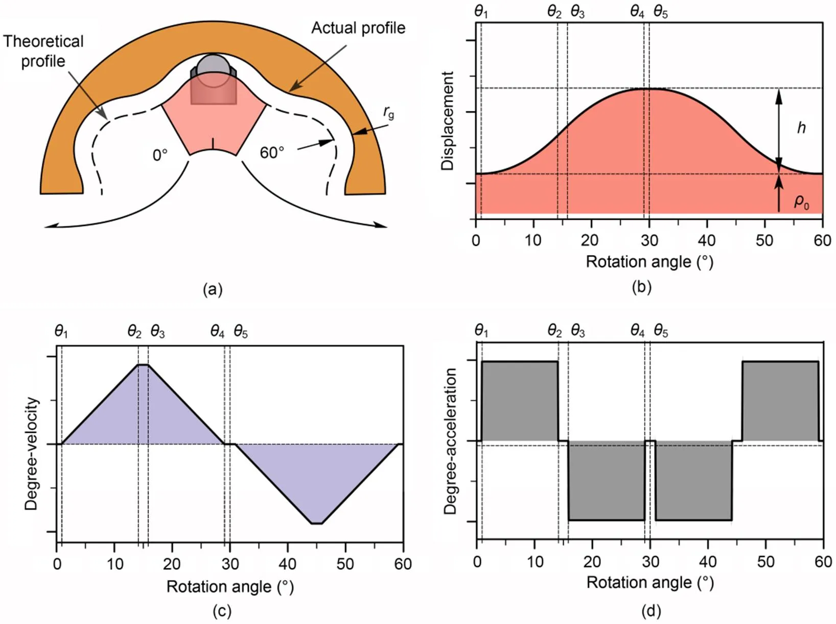
Fig. 2 Theoretical profile and kinematic characteristics of a cam ring: (a) schematic diagram of the cam ring profile with the movement of the piston and roller; (b) displacement of the theoretical profile; (c) degree-velocity of the theoretical profile; (d) degree-acceleration of the theoretical profile
The movement of the piston and roller can be divided into two parts: their telescopic movement along the cylinder block bore, and their rotation implication movement along with the rotating cylinder block. To obtain the inertial force in these two movements, the motion acceleration of the piston and roller must be known. The velocityand accelerationof the piston and roller relative to the cylinder block can be calculated as follows:


whereis the angular velocity, andvandaare the critical degree-velocity and degree-acceleration functions, respectively.
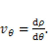
The degree-velocityvof the piston and roller with respect to the cylinder block is given by
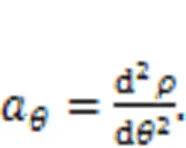
The degree-accelerationaof the piston and roller with respect to the cylinder block is given by:
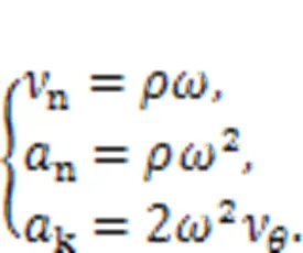
The velocity of the rotation implication motionn, the acceleration of the rotation implication motionn, and the Gauche acceleration of the piston and rollerkcan be calculated as follows:
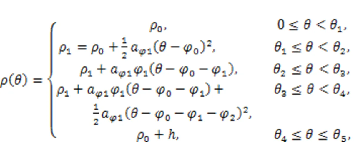
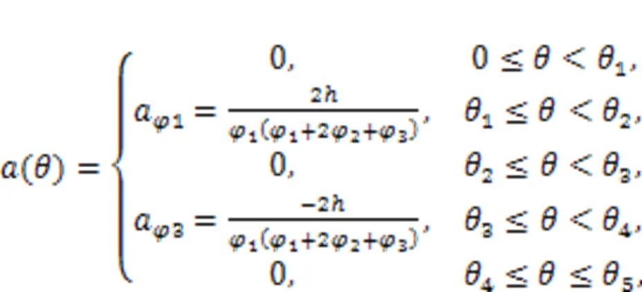
However, these kinematic characteristics are essentially determined by the cam ring profile, so the design of the profile is most important. As the most used theoretical profile of the cam ring is an equal acceleration and deceleration profile with transition zones, this was selected as the basic design in this study. The displacement(), degree-velocity(), and degree-acceleration() curves of the profile are shown in Figs. 2b?–?2d, respectively, and their equations are as follows:

3.2 Force characteristics
To calculate the deformation of the cam ring, it is essential to know the force of the roller pressing on the cam ring. Fig. 3 shows the force analysis of the piston and roller. The (,) coordinate system is set up in the roller center, while the-axis is always parallel to the central axis of the cylinder block bore. The core forces are the hydraulic forcepof the high-pressure oil on the bottom of the piston, and the supporting reaction forcenof the cam ring on the roller. The combination of these two forces keeps the hydraulic motor spinning. The inertial forces and frictional forces are also considered. The specific analysis process is as follows.
The force of the hydraulic pressurepacting on the piston chamber is:
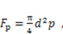
whereis the piston diameter, andis the pressure in the cylinder block.
Reciprocating the linear motion of the piston in the cylinder block bore, the inertial forceadue to the relative acceleration of the piston is:

whereis the sum of the masses of a piston and a roller.
The centrifugal forceatdue to the centripetal acceleration of the piston (n) as it rotates with the cylinder block is:

The implication motion is the rotation of the cylinder block with the Gauche inertia forcekcaused by the Gauche acceleration:

The linear frictional forces between the piston and cylinder block on two sidesf1andf2, and the rotation frictional force between the roller and cam ringf3are expressed as:
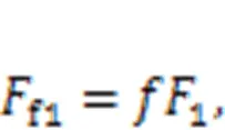
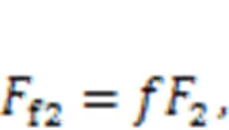
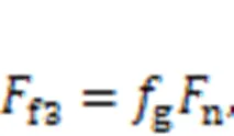
whereis the coefficient of sliding friction between the piston and cylinder block, andgis the coefficient of rolling friction between the roller and cam ring.
Eqs. (16) and (17) show the force equilibrium equations in theanddirections, respectively, while Eq. (18) is the torque equilibrium equation:
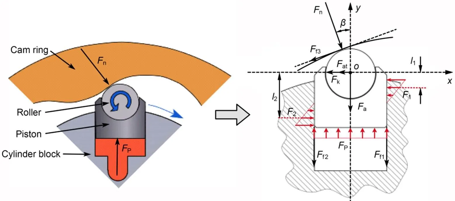
Fig. 3 Force analysis of the piston and roller


The supporting reaction force of the cam ring on the rollernis solved based on the following assumptions: the hydraulic motor rotates steadily at a very low speed, so its inertial force is very small and can be neglected, and the rotation friction forcef3is much smaller than other forces, and so can be ignored. The hydraulic forcePis considered as known, while the lateral force of the cylinder block on the pistons1,2, and the supporting reaction forcenare unknown. Thus, the supporting reaction forcencan be solved by Eqs. (16)–(18).

3.3 Deformation characteristics
Combining the actual roller working conditions and Hertzian contact theory (Johnson, 1985; Sánchez et al., 2017; Kong et al., 2018), the contact between the cam ring and roller is simplified as cylinder-to-cylinder contact with parallel axes (Nakhatakyan and Kosarev, 2012). Fig. 4 shows the simplification process. The total deformation of the cam ring is given by:
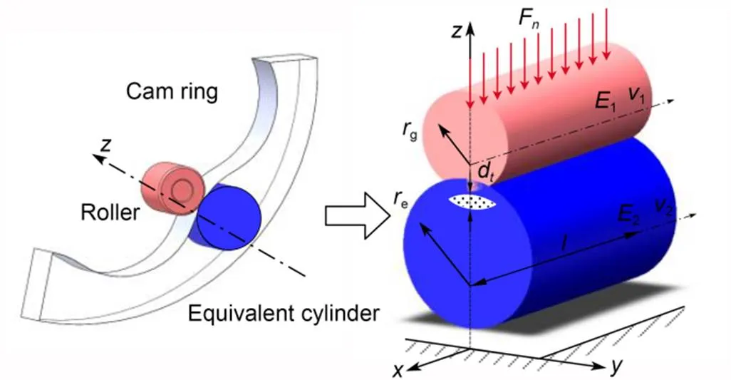
Fig. 4 Process of simplification of the roller and cam ring to Hertzian contact deformation of two parallel cylinders

For a general case, the cam ring does not have an analytic formula, especially after optimization design. The curvatureof 2D discrete data with three points (1,1), (2,2), and (3,3) can be calculated as follows:

where=1+2+32and=1+2+32, whereis an intermediate variable, and the coefficientsandcan be derived from the coordinate points (1,1), (2,2), (3,3).
When the curvatureis obtained, the curvature radiusecan be obtained from:
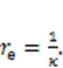
4 ?Deformation pre-compensation optimization design of cam ring
To evaluate the influence of the deformation pre-compensated optimization design of a cam ring on the pulsation characteristics of a hydraulic motor, a reasonable pulsation evaluation criterion needs to be applied. In this section, we first introduce a pulsation evaluation criterion, and then develop a deformation pre-compensated optimization approach to cam ring design to reduce the pulsations, based on the criterion.
4.1 Pulsation evaluation criterion
The speed and torque pulsation of a hydraulic motor is related to the design of the cam ring profile, and the effect of the cam ring profile on pulsation was considered in this study. The torque pulsation rate of the hydraulic motorδcan be expressed as follows:
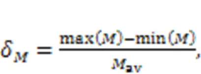
whereavis the average torque.
The instantaneous torque of the entire motorcan be considered as the sum of the torque generated by all pistons:

By substituting Eq. (24) into Eq. (23), the torque pulsation rate of the motorδcan be obtained as follows:

On the premise of ignoring power loss, if the input poweris kept constant, from=, the rotational speed pulsationδcan be expressed as

It is apparent from Eqs. (25) and (26) that the sum of all piston degree-velocities is an important indicator that plays a decisive role in the theoretical pulsation of the motor. The rotational speed pulsationδwill be used as an indicator to evaluate the merits of the curves in the optimization discussed later in this paper.
4.2 ?Deformation pre-compensated optimization design approach
Under high working pressure, elastic deformation of the cam ring is inevitable. In a hydraulic motor, the deformation of the cam ring is influenced by various factors, including the profile's shape, pressure distribution and pressure angle. The coupling of these factors leads to heterogeneous deformation distribution along the cam ring and an obvious increase in pulsation. The deformation pre-compensation optimization design approach is intended to reduce the negative effects of heterogeneous deformation on pulsation.
The deformation pre-compensation optimization design aims to preset an inward offset for the roller in advance. Because the cam ring curve is continuous and the thickness of different positions is uneven, the deformation of a point position will affect the overall performance of the entire cam ring. Thus, the overall performance is affected by offsets from each point, and unreasonable changes in the local area can even have negative effects. How to determine the amount of compensation at each point in the entire cam ring becomes a key challenge. To address this challenge, we propose a two-step deformation pre-compensated optimization design approach. The ultimate purpose of the deformation pre-compensated optimization design is to reduce the pulsation of the hydraulic motor, but the deformation pre-compensated cam ring profile is not allowed to deviate too much from the theoretical profile due to the limitation of the piston's movement. The extension length of the piston is usually set in advance to ensure a sufficient length of contact with the cylinder. The contact length will be shortened when the piston extends too much, making the cylinder block vulnerable to damage. Therefore, the deformation pre-compensation is divided into two steps. The first compensation makes the deformed profile close to the theoretical profile to maintain a sufficient contact length. The second compensation is performed to further minimize pulsation caused by the cam ring profile, mainly by fine-tuning the local profile to obtain a new profile with a minimum pulsation rate. A flow chart of the deformation pre-compensated optimization design process is shown in Fig. 5, and can be summarized in the following steps:
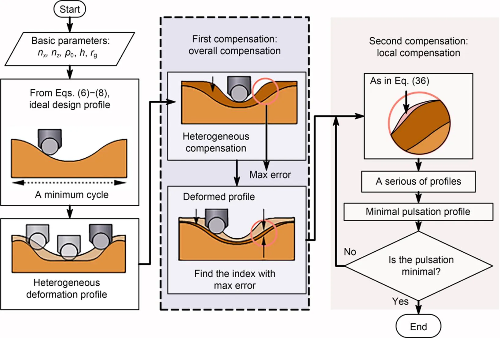
Fig. 5 Flow chart of the deformation pre-compensated optimization design process
Step 1: The theoretical cam ring profile is initially designed with equal acceleration and deceleration profiles with transition zones;
Step 2: The value of the heterogeneous elastic deformation of the cam ring is calculated;
Step 3: The deformation is fitted to a smooth curve and compensated to the overall cam ring profile;
Step 4: The local cam ring profile with the largest error is compensated again, and the profile is fine-tuned within a small range. The loop iterates until the pulsation rate no longer reduces;
Step 5: The optimized cam ring profile is obtained to achieve lower pulsation of the hydraulic motor.
A detailed calculation process of this approach was conducted to optimize the cam ring profile. The initial design of the cam ring was first carried out using the equal acceleration and deceleration profile with transition zones. Generally, the initial cam ring profile is consistently considered as a set of high-precision 2D arrays:

whereis the total number of the arrays.
It can also be converted to a rectangular coordinate system by(x,y).

The amount of deformation at pointcan be calculated by the deformation calculation process described in Section 3.3 and can be denoted asd(). Sinced() is a discrete quantity of variation, a five-polynomial fitting equation is used to express it, thus obtaining:

With the data input for thed(), the coefficient [0,1,2,3,4,5] can be calculated.

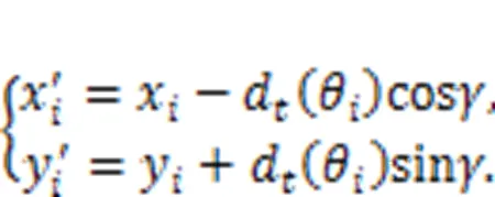
The angle γ between the compensation direction and x-axis can be calculated by trigonometric functions, thereby obtaining:
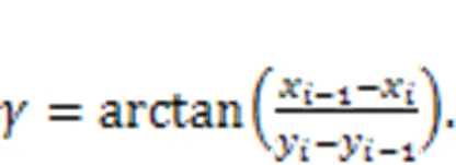
By substituting Eq. (31) into Eq. (30), the following equation can be derived:
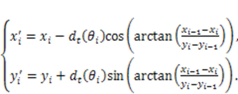

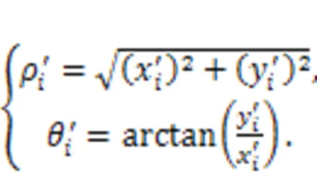
At this point, the first deformation compensation of the overall cam ring profile is complete. However, calculation results show that the cam ring profile after the first deformation compensation is close to the theoretical profile with low or even zero pulsation, but that deformation non-uniformity still exists. Thus, a second local deformation compensation is necessary based on the first deformation compensation step. Since the conventional design method is able to achieve theoretical zero pulsation without considering the deformation, it can be used as a pulsation evaluation criterion for the second local compensation. When the angles are equal, the error of the polar diameter is defined as:
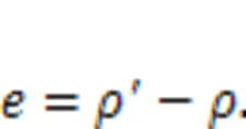


Then, the polar coordinates of these new cam ring profiles can be converted to Cartesian coordinates, giving:
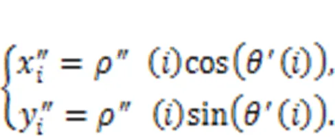

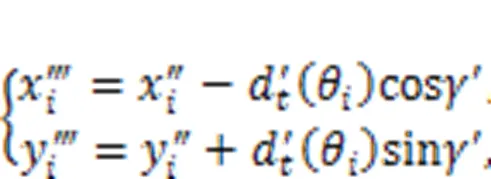
The result of these new deformed cam ring profiles in polar coordinates can further be obtained:
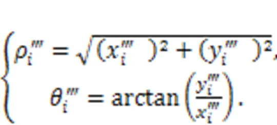
The deformed degree-velocity can be obtained from:
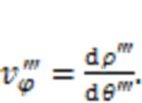
The pulsation rate is calculated for this series of profiles, as follows:
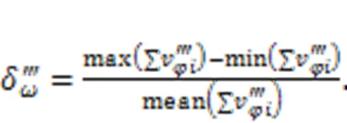
The profile with the lowest pulsation rate can be found as the output of the second local compensation step. Finally, this compensation process is repeated until the pulsation rate no longer drops.
5 Case study and discussion
A case study was used to verify the feasibility and effectiveness of the proposed deformation pre-compensation optimization design approach. The correctness of the design approach was verified by the finite element simulation of this case. A comparison of pulsation between deformation pre-compensated and uncompensated cam ring profiles was conducted to demonstrate the benefits of the deformation pre-compensated optimization design approach.

Table 1 Basic design parameters of the cam ring in the case study
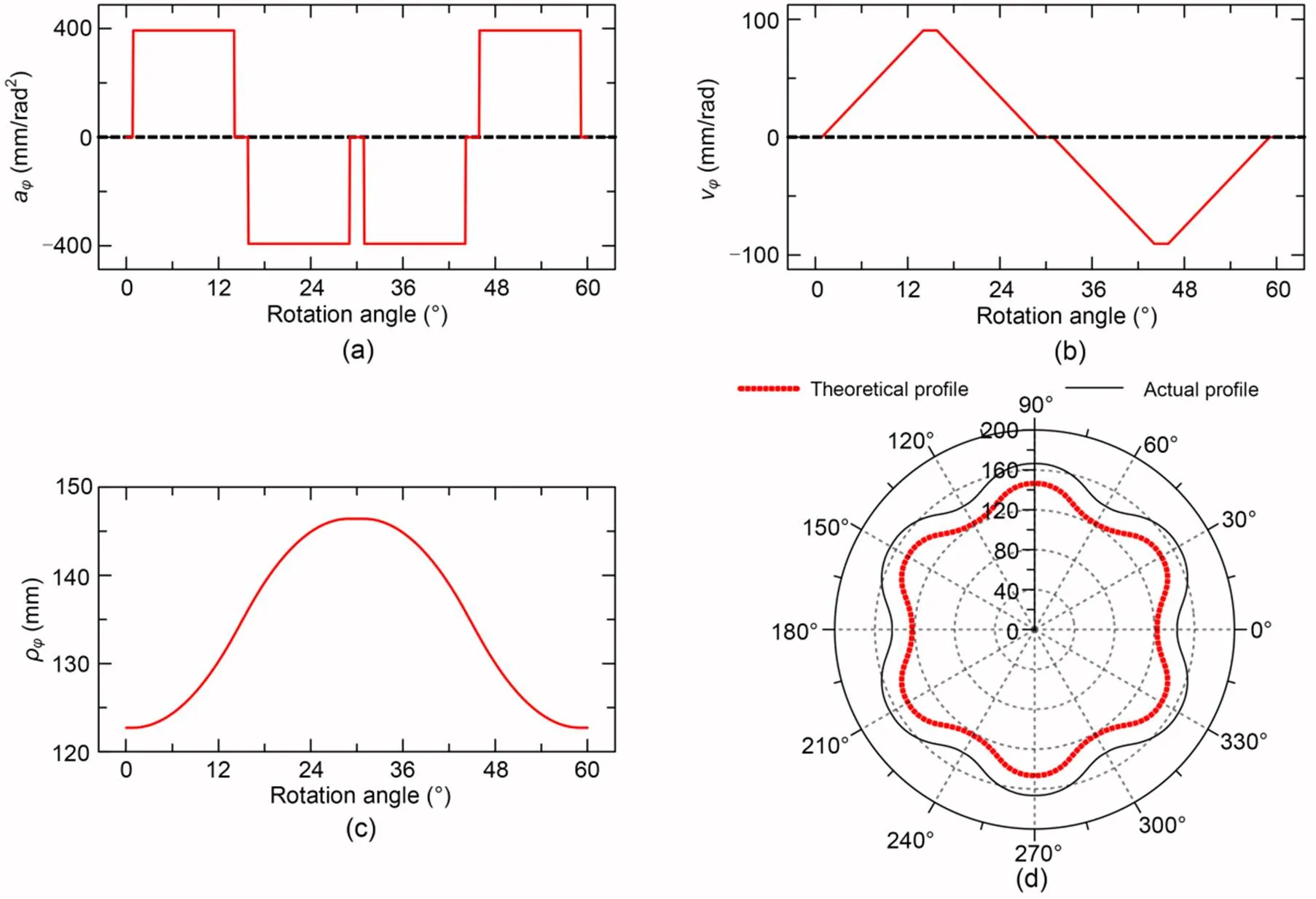
Fig. 7 Initial cam ring theoretical profile and the kinematic characteristics: (a) degree-acceleration of a minimum working cycle curve; (b) degree-velocity of a minimum working cycle curve; (c) displacement of a minimum working cycle curve; (d) the entire cam ring profile
5.1 Design case
The basic design parameters of a cam ring are shown in Table 1. A widely used design method of equal acceleration law was used for the initial design of the basic theoretical profile. The kinematic equations of the cam ring profile can be obtained from the kinematical analyses inSection 3.1. Figs. 7a?–?7c respectively show the degree-acceleration, degree velocity, and displacement of a minimum working cycle in the cam ring profile, while the entire cam ring profile is shown in Fig. 7d. Without considering the influence of cam ring deformation, the general design of the cam ring profile is complete. However, the deformation pre-compensation optimization design of the cam ring was conducted to further reduce the pulsation of the hydraulic motor in this study.
It is apparent that the angle of a minimum working cycle curve is 60° in this case. Since the minimum working cycle curve is symmetric, only half (30°?) needs to be analyzed and used for calculation. The roller was made of GCr15SiMn, while the cam ring was made of 20CrMnMo. Table 2 shows the basic material parameters of the roller and cam ring. The supporting reaction force of the cam ring on the rollernand the curvature radiuseare essential parameters for calculating the amount of cam ring deformation. Fig. 8a shows the calculated results of the supporting reaction forcenby Eq. (19), with the friction coefficientset as 0.1 based on published experimental results (Olsson and Ukonsaari, 2003; Isaksson et al., 2009). Fig. 8b shows the calculated curvature results of the deformed cam ring. The arrow length represents the magnitude of curvature, and the arrow direction represents the contact type (the right-facing arrow indicates the external contact, and the left-facing arrow indicates the internal contact).
The amount of deformationdin Fig. 8c indicates the elastic deformation of the cam ring under a high hydraulic pressure of 45 MPa in half of a minimum working cycle curve (0°?–?30°). Fig. 8d shows the difference between the cam ring profiles with and without considering deformation. The actual cam ring profile with deformation is shifted outward by a certain distance compared to the theoretical ideal design profile without deformation, and the distance between them is not uniformly distributed at different rotation angles.

Table 2 Material parameters of roller and cam ring
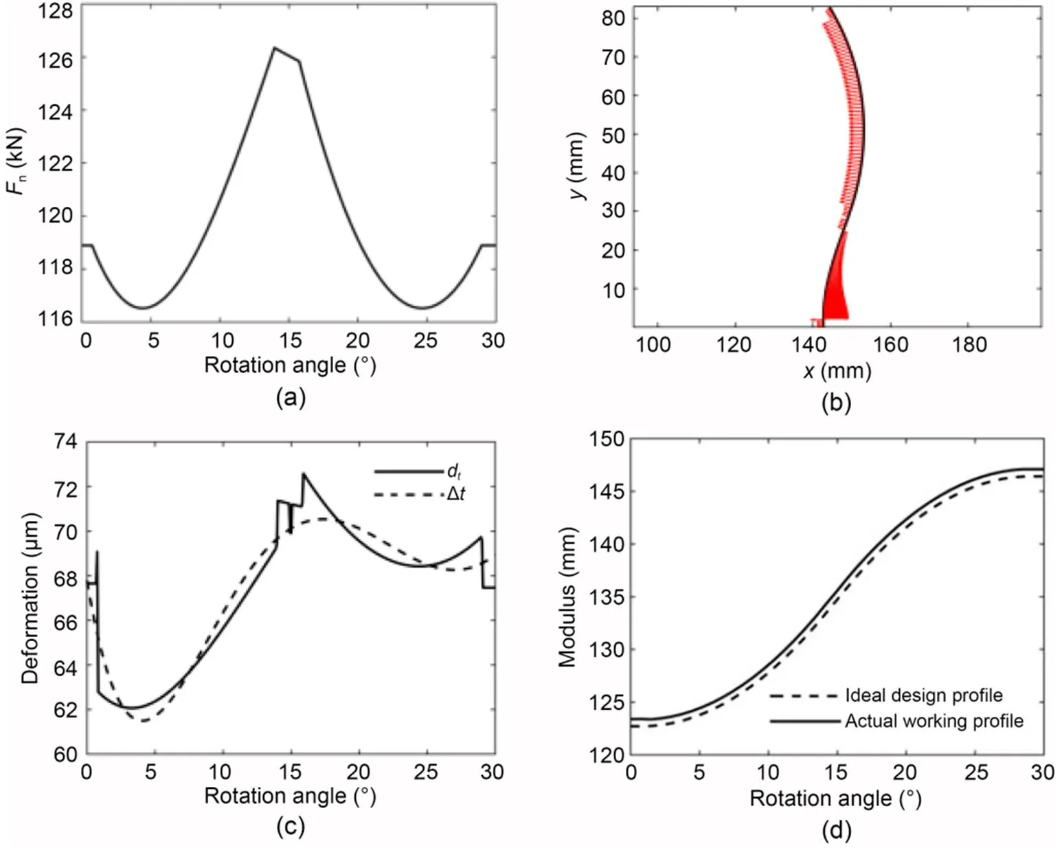
Fig. 8 Elastic deformation of the profile and its process variables: (a) force along the cam ring; (b) curvature of the cam ring; (c) calculated deformation amount; (d) theoretical profile and the profile after deformation
Note that in Fig. 8c the deformation curve of the cam ring (as indicated by the solid line) is subject to abrupt changes at different rotation angles. It is difficult to achieve deformation compensation of such an abrupt curve. The deformation curve of the cam ring needs to be fitted to a smooth curve (as indicated by the dotted line). In this study, a fifth order polynomial equation was used to fit the deformation curve. According to the detailed process of the two-step compensation approach described inSection 4.2, the first deformation compensation makes a deformed profile close to the theoretical one to keep a sufficient contact length. Then, a second compensation is performed to obtain the cam ring profile with the lowest pulsation rate, mainly by fine-tuning the local profile. The compensation iterative optimization process (Fig. 9a) generates a series of new cam ring profiles, as depicted in Eq. (35). Based on the pulsation evaluation criterion proposed in Section 4.1, the cam ring profile with the least pulsation could be selected. Fig. 9b shows the final compensation results, in which the ideal design profile without considering deformation (as indicated by the black solid line) is a theoretical zero-pulsation ideal design situation. When a cam ring profile is close to or even overlaps with this ideal design profile, its speed and torque pulsations are low or even zero. When this ideal design profile of cam ring is subjected to a certain amount of deformation, it will be pushed outward away from the circle center of cam ring and thus becomes the actual working profile (as indicated by the black dotted line). It can be found that the deformation obviously makes it far away from the ideal design profile, indicating the formation of a certain amount of pulsations. Using the design compensated optimization design approach, the compensation design profile (as indicated by the red solid line) of cam ring can be obtained. It is apparent that the compensation design profile is closer to the circle center of cam ring than the ideal design profile. When this compensation design profile of cam ring is subjected to a certain amount of deformation, it will be pushed outward away from the circle center of cam ring and thus becomes the compensation working profile (as indicated by the red dotted line). It is worth noting that the compensation working profile is close to the ideal design profile, indicating its pulsation is lower than that of the actual working profile.
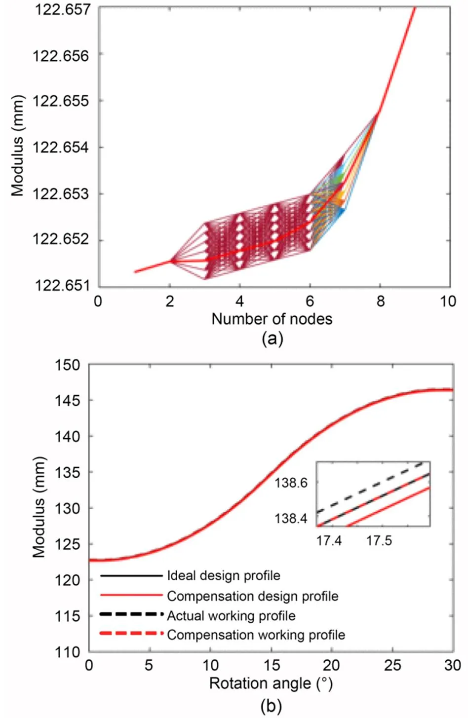
Fig. 9 Typical second compensation process and final compensation results: (a) local optimization process; (b) final compensation results
5.2 Verification of the optimization design approach
The deformation compensated optimization design approach is achieved by combining the ideal design profile and deformation degree. The ideal design profile results from the pre-determined equal acceleration and deceleration profile. Thus, the correctness of the deformation compensated optimization design approach can be directly determined by the correctness of the deformation calculation. In this section, the deformation calculation is verified by finite element simulation. A simulation of cam ring deformation was performed at a working hydraulic pressure of 45 MPa based on the material parameters and design parameters mentioned above. Fig. 10 shows the simulation results, in which seven positions (at 5° intervals of the minimum 30° cycle) of deformation cloud pictures are displayed. The simulated deformation values of the cam ring at these seven positions were compared with the calculated deformation values shown in Section 3.3. It is apparent from the bar graph that the simulated values are in good agreement with the calculated values. The error values between simulated and calculated deformation are shown in Table 3, in which the average error of all positions is only about 3.19% and the maximum error is 6.57%. This result indicates the deformation calculation is reliable and accurate. Thus, the deformation compensated optimization design approach combining the ideal design profile and deformation value is effective and feasible.
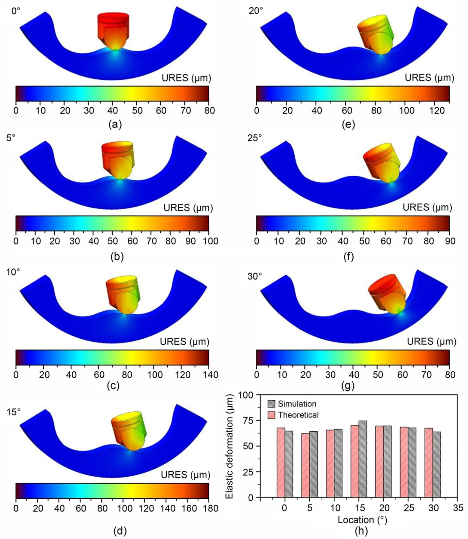
Fig. 10 Finite element simulation results at different positions (a)–(g), and the comparison between deformation values obtained by simulation and theoretical calculation (h). URES represents the resultant displacement
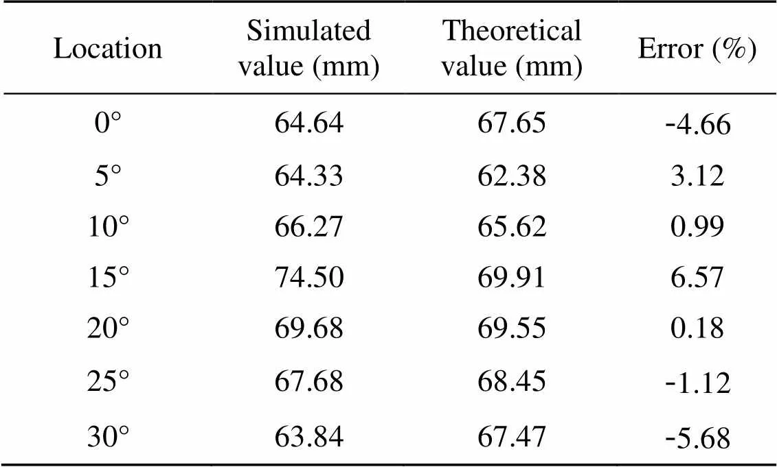
Table 3 Error between the simulated and calculated deformation values
5.3 Pulsation analysis
Based on the pulsation calculation method described in Section 4.1, the pulsation rates of both the deformation compensated and uncompensated situations at different working pressures can be obtained (Fig. 11a). The pulsation rate after deformation compensation is significantly lower than that without compensation. The pulsation reduction rates of deformation compensated and uncompensated situations were also calculated (Fig. 11b). The pulsation reduction rate increased with the increase of working pressure. This is normal because a high working pressure will cause more deformation of the cam ring, and thus the compensation effect is also more obvious. When the working pressure of the hydraulic motor is higher than 20 MPa, the pulsation reduction rate is more than 30%. As the working pressure goes up to 45 MPa, the pulsation reduction rate can reach 40%. These pulsation results indicate the deformation pre-compensated optimization design approach can significantly reduce the pulsation of cam-lobe radial-piston hydraulic motors.
To verify the effectiveness of the proposed deformation pre-compensated optimization design approach, an optimized cam ring was manufactured and applied to a motor prototype to test the pulsation. The pulsation test rig and its hydraulic schematic diagram are illustrated in Fig. 12. In the testing process, the same type of hydraulic motor was used as the tested and loading motor to make the tested motor rotate passively, and the load was carried out through the overflow valve at the oil outlet. The experimental data were collected by a speed sensor installed on the connecting shaft. Fig. 13 shows the experimental results of instantaneous speed variation at different working pressures from 5 to 30 MPa. For each working pressure, the speed pulsation can be calculated by the difference between the maximum and minimum speeds divided by the average value of all instantaneous speeds. The experimental speed pulsation values at different working pressures are indicated by solid triangles in Fig. 11. All experimental speed pulsation values agree with the simulated values for the deformation compensated case, indicating that the deformation pre-compensation optimization approach to cam ring design is effective.

Fig. 11 Pulsation simulation results of deformation compensated/un-compensated situations, and pulsation experimental results of deformation compensated situation (a); pulsation reduction rates at different working pressures (b)
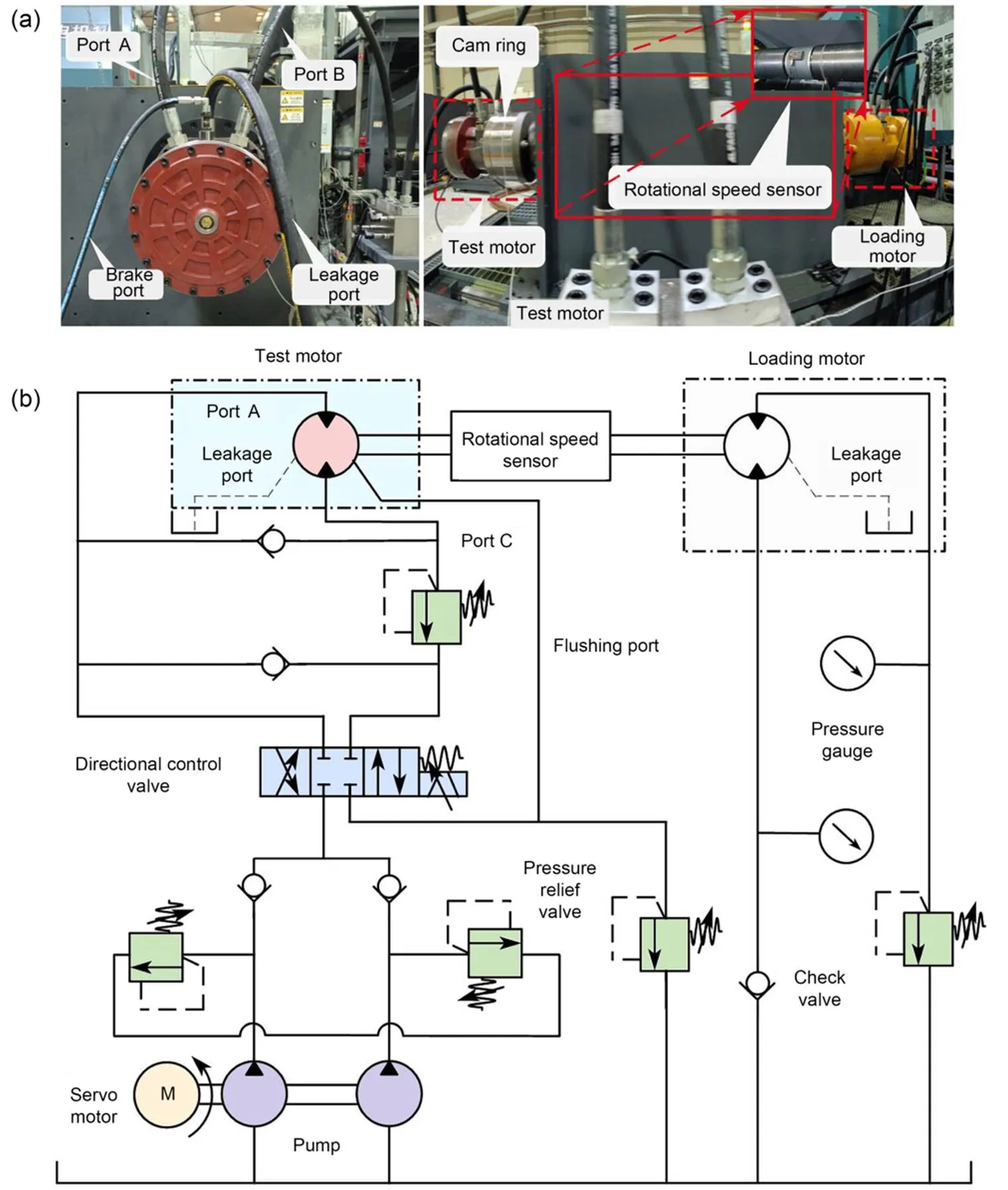
Fig. 12 Photo of the test rig and tested motor (a) and hydraulic schematic of test rig (b)
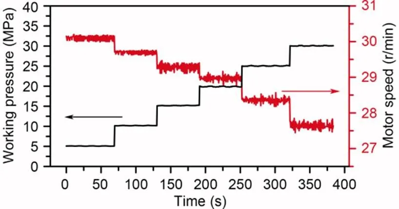
Fig. 13 Experimental results of instantaneous speed variation at different working pressures
6 Conclusions
In this paper, a deformation pre-compensated optimization approach to cam ring design is proposed to reduce the pulsation of cam-lobe radial-piston hydraulic motors. The main conclusions are as follows:
1. A two-step deformation pre-compensated optimization approach to cam ring design was developed, including an initial overall compensation process and a second local compensation process.
2. A process for calculation of cam ring deformation was derived based on a detailed kinematic and force analysis of a hydraulic motor, and verified by finite element simulation method in a case study.
3. The pulsation reduction rate increases as working pressure increases, and a high pulsation reduction rate of 40% can be achieved at a high working pressure of 45 MPa.
This work is supported by the National Key R&D Program of China (No. 2021YFB3400501) and the National Science Foundation of China (Nos. 52105070 and U21B2074).
Chao ZHANG, Hao TAN, Bing XU, and Junhui ZHANG designed the research. Chao ZHANG, Hao TAN, Yu FANG, Xiaolong ZHANG, Yu YANG, Yiman DUAN, Min HAN, and Shaojian CUI processed the corresponding experiments and data. Chao ZHANG, Hao TAN, and Junhui ZHANG wrote the first draft of the manuscript. Chao ZHANG, Hao TAN, and Junhui ZHANG revised and edited the final version.
Chao ZHANG, Hao TAN, Yu FANG, Xiaolong ZHANG, Yu YANG, Yiman DUAN, Min HAN, Shaojian CUI, Bing XU, and Junhui ZHANG declare that they have no conflict of interest.
Dasgupta K, Mandal SK, Pan S, 2012. Dynamic analysis of a low speed high torque hydrostatic drive using steady-state characteristics., 52:1-17. https://doi.org/10.1016/j.mechmachtheory.2011.12.004
Isaksson P, Nilsson D, Larsson R, 2009. Elasto-hydrodynamic simulation of complex geometries in hydraulic motors., 42(10):1418-1423. https://doi.org/10.1016/j.triboint.2009.05.018
Johnson KL, 1985. Contact Mechanics. Cambridge University Press, Cambridge, UK. https://doi.org/10.1017/CBO9781139171731
Kong FZ, Huang WT, Jiang YC, et al., 2018. A vibration model of ball bearings with a localized defect based on the Hertzian contact stress distribution., 2018:5424875. https://doi.org/10.1155/2018/5424875
Lassaad W, Mohamed T, Yassine D, et al., 2013. Nonlinear dynamic behaviour of a cam mechanism with oscillating roller follower in presence of profile error., 8(2):127-136. https://doi.org/10.1007/s11465-013-0254-x
Lewis R, 2009. Friction in a hydraulic motor piston/cam roller contact lined with PTFE impregnated cloth., 266(7-8):888-892. https://doi.org/10.1016/j.wear.2008.12.009
Lin DY, Hou BJ, Lan CC, 2017. A balancing cam mechanism for minimizing the torque fluctuation of engine camshafts., 108:160-175. https://doi.org/10.1016/j.mechmachtheory.2016.10.023
Lin RC, Wei SS, Yuan XL, 2010. Low-speed instability analysis for hydraulic motor based on nonlinear dynamics.(), 16(3):?328-332. https://doi.org/10.1007/s12404-010-0322-3
Liu Y, Gu LC, Yang B, et al., 2018. A new evaluation method on hydraulic system using the instantaneous speed fluctuation of hydraulic motor., 232(15):2674-2684. https://doi.org/10.1177/0954406217722576
Liu YS, Deng YP, Fang MS, et al., 2017. Research on the torque characteristics of a seawater hydraulic axial piston motor in deep-sea environment., 146:411-423. https://doi.org/10.1016/j.oceaneng.2017.10.004
Lyu F, Zhang JH, Zhao SJ, et al., 2022. Coupled evolution of piston asperity and cylinder bore contour of piston/cylinder pair in axial piston pump., in press. https://doi.org/10.1016/j.cja.2022.09.001
Mehta V, Rath SN, 2021. 3D printed microfluidic devices: a review focused on four fundamental manufacturing approaches and implications on the field of healthcare., 4(2):311-343. https://doi.org/10.1007/s42242-020-00112-5
Nakhatakyan FG, Kosarev OI, 2012. An analytical method for solving a problem of cylinder-to-cylinder contacts at misalignment., 41(2):137-140. https://doi.org/10.3103/S1052618812020124
Nguyen TTN, Kurtenbach S, Hüsing M, et al., 2019. A general framework for motion design of the follower in cam mechanisms by using non-uniform rational B-spline., 137:374-385. https://doi.org/10.1016/j.mechmachtheory.2019.03.029
Nguyen VT, Kim DJ, 2007. Flexible cam profile synthesis method using smoothing spline curves., 42(7):825-838. https://doi.org/10.1016/j.mechmachtheory.2006.07.005
Olsson H, Ukonsaari J, 2003. Wear testing and specification of hydraulic fluid in industrial applications., 36(11):835-841. https://doi.org/10.1016/S0301-679X(03)00101-4
Pettersson U, Jacobson S, 2007. Textured surfaces for improved lubrication at high pressure and low sliding speed of roller/piston in hydraulic motors., 40(2):355-359. https://doi.org/10.1016/j.triboint.2005.11.024
Qiu H, Lin CJ, Li ZY, et al., 2005. A universal optimal approach to cam curve design and its applications., 40(6):669-692. https://doi.org/10.1016/j.mechmachtheory.2004.12.005
Sánchez MB, Pleguezuelos M, Pedrero JI, 2017. Approximate equations for the meshing stiffness and the load sharing ratio of spur gears including hertzian effects., 109:231-249. https://doi.org/10.1016/j.mechmachtheory.2016.11.014
Shi J, Ren Y, Tang H, Xiang J, et al., 2022. Hydraulic directional valve fault diagnosis using a weighted adaptive fusion of multi-dimensional features of a multi-sensor., 23(4):257-271. https://doi.org/10.1631/jzus.A2100394
Sj?din UI, Olofsson ULO, 2003. Initial sliding wear on piston rings in a radial piston hydraulic motor., 254(11):1208-1215. https://doi.org/10.1016/S0043-1648(03)00337-5
Sun JP, Tang ZP, 2011. The parametric design and motion analysis about line translating tip follower cam mechanism based on model datum graph., 23:439-444. https://doi.org/10.1016/j.proeng.2011.11.2527
Tao J, Wang HY, Liao HH, et al., 2019. Mechanical design and numerical simulation of digital-displacement radial piston pump for multi-megawatt wind turbine drivetrain., 143:995-1009. https://doi.org/10.1016/j.renene.2019.04.159
Wang HZ, 2017. Research on Key Technologies of Radial Piston Hydraulic Motor with Multi-Action Inner Curves. MS Thesis, Lanzhou University of Technology, Lanzhou, China (in Chinese).
Wang ZQ, 2014. Research on the Key Technology of Incurve Type Water Hydraulic Motor with Low Speed High Torque. PhD Thesis, Yanshan University, Qinhuangdao, China (in Chinese).
Wang ZQ, Xiang JB, Fu Q, et al., 2022. Study on the friction performance of textured surface on water hydraulic motor piston pair., 65(2):308-320. https://doi.org/10.1080/10402004.2022.2027589
Xin JB, 2019. Research on Generalized Stator Orbit Curve of Radial Piston Motor. MS Thesis, Nanchang University, Nanchang, China (in Chinese). https://doi.org/10.27232/d.cnki.gnchu.2019.001965
Yu HY, Zhong HT, Li S, 2012. The analysis on the flow pulsation of radial piston motor with the modified heart-shaped curve as inner curve., 44(3):44-48 (in Chinese).
Zhang C, Wang S, Li J, et al., 2020. Additive manufacturing of products with functional fluid channels: a review., 36:101490. https://doi.org/10.1016/j.addma.2020.101490
Zhang C, Zhu PG, Lin YQ, et al., 2021. Fluid-driven artificial muscles: bio-design, manufacturing, sensing, control, and applications., 4(1):123-145. https://doi.org/10.1007/s42242-020-00099-z.
Zhang K, Zhang JH, Gan MY, et al., 2022. Modeling and parameter sensitivity analysis of valve-controlled helical hydraulic rotary actuator system., 35(1):66. https://doi.org/10.1186/s10033-022-00737-w.
Zhang XL, Zhang JH, Xu B, et al., 2021a. The effect of slotted hole on minimum oil film thickness of piston in radial piston hydraulic motor. ASME/BATH Symposium on Fluid Power and Motion Control, Article V001T01A054. https://doi.org/10.1115/FPMC2021-69937
Zhang XL, Zhang JH, Zhang HJ, et al., 2021b. Optimized design of cam ring curve of cam lobe radial-piston motor.(), 49(10):30-35 (in Chinese). https://doi.org/10.13245/j.hust.211005
Zhou CJ, Hu B, Chen SY, et al., 2016. Design and analysis of high-speed cam mechanism using Fourier series., 104:118-129. https://doi.org/10.1016/j.mechmachtheory.2016.05.009
Nov. 20, 2022;
Revision accepted Jan. 2, 2023;
Crosschecked Feb. 6, 2023
? Zhejiang University Press 2023
 Journal of Zhejiang University-Science A(Applied Physics & Engineering)2023年2期
- Journal of Zhejiang University-Science A(Applied Physics & Engineering)的其它文章
- Biophysical neurons, energy, and synapse controllability: a review
- Advanced ocean wave energy harvesting: current progress and future trends
- Reliability measure approach considering mixture uncertainties under insufficient input data
- Preparation and 3D printing of high-thermal-conductivity continuous mesophase-pitch-based carbon fiber/epoxy composites
