
Analysis of the effect of bore centerline on projectile exit conditions in small arms
2022-12-23 04:30:02DvidLeonhrdtMrkGrnichMiljenkoLucic
Defence Technology 2022年12期
Dvid Leonhrdt ,Mrk Grnich ,Miljenko Lucic
a College of Engineering,University of Canterbury,Private Bag 4800,Christchurch,8140,New Zealand
b Novacam Technologies Inc.,277 Lakeshore Road Suite #4,Pointe-Claire,Quebec,H9S 4L2,Canada
Keywords:Finite element analysis Small arms Barrel dynamics Bore centerline
ABSTRACT Most finite element models of small arms focus on an idealized barrel,typically one with a perfectly straight bore centerline.Using five different experimentally measured bore centerlines,this investigation analyzes the effect centerline nonlinearity has on projectile exit conditions.This includes the effect of rotating a centerline through several orientations.Modeled using Abaqus/Explicit,this dynamic analysis simulates a single firing cycle for each centerline.Projectile jump is calculated for each model as a measure of the effects of warped centerlines.The warped centerlines have a small effect on barrel dynamics.
1.Introduction
Bore curvature has the potential to induce projectile movement relative to the barrel(balloting)and affect projectile exit conditions in ways detrimental to precision.While more pronounced in large guns due to the greater compliance of sabots and obturators relative to solid projectiles,effects are still present in the context of small arms and remain important for direct-fire applications.In the context of this work,“bore curvature”should be taken to refer to curvature which spans the entirety of the barrel and is not concerned with unrelated smaller scale defects such as poorly machined rifling.
General modeling projectile/bore interaction has been the subject of previous research,primarily when dealing with large guns such as artillery pieces and tank guns.Methods for modeling this interaction include beam formulations(typically Euler-Bernoulli)solved through finite element analysis[1]and solid continuum element models[2].The present effort uses the later technique.Thorough review of general modeling techniques is of limited relevance,as is literature focusing on non-curvature related defects.Emphasis will be placed on those papers which have included bore curvature as a factor during modeling.
Neglecting thermal effects during repeated firing,curvature of the bore centerline can be attributed to two factors:droop due to gravity and manufacturing variability(hereafter referred to as warp).Droop has been modeled exclusive of warp in the context of both the primary object of study[3]and as a secondary model feature in related research efforts[4-6].Warp has also been modeled in the absence of droop[7-9].However,it is more common that models incorporate both droop and experimentally measured warp.These efforts include both those where the bore curvature is the object of study[10,11]and those where it is treated as an incidental model feature[12-19].
Chen used measured barrel data to create a parametric model capable of generating a number of centerline variations for a large smooth-bore gun[8].He showed that bore curvature contributed strongly to lateral projectile movement,with the effect exaggerated for curvature near the muzzle.Eichhorst et al.discuss several methods by which centerline curvature may be included in finite element models[9].Using a M4 barrel,they showed that a nonideal bore resulted in pitching and yawing motion,though of lesser significance than off-axis masses attached to the barrel.
This paper presents measured bore centerlines for five steel barrels.These centerlines are implemented in a finite element model to assess the effect each centerline has on projectile exit conditions.A single centerline is then rotated through four different orientations in order to investigate effects of barrel installation orientation.
2.Experimental methodology
This investigation combines bore measurements of a sample of barrels with an implementation of those measurements into a finite element model.Barrels are not manufactured perfectly,such that their centerlines are not truly straight.Including this defect in a model adds additional fidelity and allows examining the effect of barrel centerline variations on projectile exit conditions.
2.1.Bore measurements
Five barrels,nominally manufactured in an identical manner,were provided by Hardy Rifle Engineering.Centerline measurements for each barrel were conducted by Novacam Technologies,a company specializing in non-contact 3D metrology.Barrels were 609.6 mm(24 in)in length and chambered in 6.5 Creedmoor.An optical measurement technique was used,in which the barrels were fixed in a vertical orientation to eliminate gravity effects and a probe connected to an interferometer was lowered through the bore(Fig.1).Measurements were taken at 89 locations,6.35 mm apart,and center coordinates calculated for each position using an average of the coordinates of all the surface points scanned at that location.The center coordinate is therefore the geometric centroid of those points.Although the surface was scanned,the surface details were not retained for use in the model.These measurements were taken along the bore,starting at the end of the chamber and extending to the muzzle.
Fig.1.Novacam measurement apparatus with barrel clamped vertically to eliminate gravity effects.
The raw data is given relative to the axis of travel of the probe.Whether this axis is parallel to the nominal bore-axis is a matter of fixturing.Rather than rely on positioning during measurement,the data is shifted such that the start and end of the data are on the nominal bore-axis.This is a reasonable assumption,as the barrel contouring process used for these barrels indexes using the bore in such a way that the barrel outer surface is concentric with the bore at both ends.
Fig.2 shows the total measured deviation from a straight centerline for each of the five barrels.This data has already been shifted as described above.Fig.3 shows the components of warp in the horizontal(top)and vertical(bottom)planes.Each data set was rotated about the nominal barrel axis in a way that maximizes deflection in the vertical plane for ease of comparison.Note the scale of the horizontal deviation relative to the vertical in Fig.3 and the similar mismatch in scale seen in Fig.2.In both cases this exaggeration was included to allow easier examination of the differences in centerlines.In reality,the horizontal deviation is on the order of 3%of the vertical.This indicates the warp is nearly planer as is also suggested by the similarity between the total and vertical deviations.
Examination of Fig.3 reveals apparent smaller scale localized curvature,especially notable for Centerline 5 between 200 and 300 mm.This is measurement noise,an assertion verified through repeated measurement of a single barrel.Note that if this smaller scale behavior was real,finite element techniques exist by which these features could be included[20].
3.Modeling methodology
A parametric finite element(FE)model was developed for study of the effects of various physical features on the projectile and barrel dynamics.To facilitate the parametric framework,the Python scripting features of Abaqus/CAE were used.Parameters that are easily modified include barrel length,caliber,chambering,rifling pattern,centerline profile,material properties,and projectile initial position.The model is modular in regards to action/receiver geometry and projectile;various projectiles and receiver geometries may be imported from manually created component libraries.
3.1.Geometry
Excluding the rifling,the idealized barrel is axisymmetric.The cyclic symmetry of the rifled barrel was utilized to generate the rifled barrel geometry.This geometry was created by extruding individual portions of the barrel with a twist(i.e.individual lands,wedges of the barrel)and all merged into a final geometry.Preserving internal boundaries during the merging process provides the partitions necessary to create a high-quality hexahedral FE mesh.The cross-section geometry is generated by the script based on the number of lands,the land:groove ratio,the cant angle,bore diameter,and groove diameter.Each of the cross-sections is extruded based on barrel twist rate,patterned radially a number of times equal to the number of lands,and then merged into a single solid geometry.
Fig.2.Total magnitude of deviation from straight centerline for the five barrels.
Fig.3.Horizontal and vertical deviation from straight centerline for the five barrels.
Adding additional details to the geometry(chamber,outer contour)was accomplished using a series of cut operations,similar to those used in the actual machining of barrels.The barrel model used in this investigation is based on the firearm chosen for the model,a Ruger Precision Rifle chambered in 6.5 Creedmoor.It features conventional 6-groove rifling with a 1-in-8 inch twist rate and is 609.6 mm(24 in)in length.The barrel was assigned the properties of 416R stainless steel to match the test barrel.Elastic properties for all materials used in the model are found in Table 1.
This project used a projectile design produced by Sierra Bullets,the 140 grain BTHP SMK(Boat Tail Hollow Point Sierra MatchKing)depicted in Fig.4.Though there are many variants,this basic projectile design is ubiquitous,consisting of a gilding metal jacket stretched over a lead-antimony core.Elastic-plastic properties used in the model for these two materials are shown in Tables 1 and 2.The non-linear behavior is approximated as piecewise linear.The interface between the core and jacket was assumed perfectly bonded.The projectile is partitioned such that the mesh is generated with a twist rate matching that of the rifling,a feature that provides for a high quality mesh of hexahedral elements.
Many previous investigations of barrel behavior have included only the barrel and projectile geometries.This limits their usefulness as predictive tools,as action/receiver geometry has a significant effect on barrel dynamics[21].The importance of including asymmetric recoiling masses and boundary conditions in modeling efforts has been known for many years[13].The ideal approach would be to include the full geometry of the firearm.However,a balance of efficiency and accuracy must be considered.Here we included an accurate representation of the barrel,a good representation of the receiver and approximate representations of the remainder of the rifle assembly.The main objective of the remaining components was a reasonable representation of stiffness and an accurate representation of total mass and mass center location.

Fig.4.Sierra MatchKing 140 grain projectile used in modeling and validation efforts.
The action used in this investigation is based on the Ruger Precision Rifle.A small number of simplifications have been made to the geometry to aid the meshing process.The bolt is not modeled,the bolt face is instead integrated directly into the action geometry to form a pressure boundary surface so that total recoil forces are accounted for,and the ejection port has been shifted 0.89 mm in order to line up precisely with the magazine well.The action was assigned material properties corresponding to 4140 stainless steel(Table 1).

Table 1 Elastic properties for all materials in model.
Table 2 Plastic properties for projectile materials.
The receiver geometry adds asymmetry to the model but is not sufficient to capture the offset between the center-of-mass(CoM)of the firearm and the line of action of the recoil force created by the propellant gas pressure.It is therefore not sufficient to capture the recoil moment generated by that offset.
To account for total mass,allow for simple variation of CoM location,and better capture the way in which recoil forces are transferred to the chassis of the rifle,three additional features were created.Shown in Fig.5,two pillars were added at the location of the action screws,which fasten the action to the rest of the firearm,and an additional block of material was added to the rear of the receiver.These components have densities such that they represent the mass of all components not explicitly included in the model.Variation in the size and densities of each part allow the model center-of-mass to be shifted.This eccentric mass is the primary driver of recoil moment and lateral vibration in the vertical plane.It is also possible to modify the modulus of the pillars and block to vary the stiffness of the connection with the masses they account for.This approach effectively changes the model CoM to capture the recoil moment during the firing cycle while deviating<5%from the firearm's mass moment of inertia as measured using a trifilar pendulum.
A downside of the geometry described is an approximated representation of structural stiffness.On the actual firearm a Picatinny rail is fastened to the top of the upper receiver and the lower receiver is mated to the upper in such a way as to resist bending.
3.2.Internal ballistics
Accurate application of pressure boundary conditions requires the pressure to vary both spatially and temporally.This means computing pressure curves for each axial position along the length of the bore.The approach used in this study uses the internal ballistics(IB)program QuickLOAD coupled with the Lagrangeapproximation to preformulate a breech pressure history based on assumed ballistic parameters.Pressure distribution based on projectile location is then calculated and applied by a user subroutine in each increment.
Fig.5.Full model geometry used in this investigation.Receiver,barrel,and additional masses are shown.
The Lagrange approximation assumes propellant gas density is independent of axial position and that the velocity of the propellant gas varies linearly from zero at the breech to the bullet velocity at the base of the projectile.Calculations begin with Eq.(1),which relates the breech pressure,PBreech,to the pressure at the base of the projectile,PBase,for any point in time.Here c is propellant mass,w is the projectile mass,and PLossis a representation of the resistive forces in the system,i.e.friction on the projectile and compression of gas in front of the projectile.Derivation and further details are covered by Corner[22]and Carlucci and Jacobson[23].
The breech and base pressure can then be used to determine the pressure of any intermediate point at an arbitrary time,P(x,t),using Eq.(2).Here x is the location of interest,for x≤y(t),where y(t)is the time-dependent position of the projectile.Eq.(2)is sufficient to define the pressure boundary conditions for this investigation when evaluated at the location of each ring of elements along the bore.The chamber was assumed to experience the breech pressure along its entire length.
Eq.(2)is implemented within a user subroutine.At each time step,the subroutine checks for nodes belonging to the wetted surface,and calculates the appropriate pressure based on location on a node-by-node basis.Note that QuickLOAD accounts for losses(primarily friction)through the use of an internal weighting parameter which is functionally equivalent to increasing the mass of the projectile.This is significant,because the pressure,displacement,and velocities estimated by the IB program are computed with an assumed loss factor.In order for the finite element prediction to agree with the values produced by the IB calculator the FE projectile/bore interaction should then include a similar resistance.However,for reasons that are not clear,the best match is obtained by the implementation of frictionless contact.Therefore,PLoss(t)for this model is zero for all points in time.
The pressure curve is computed a priori and does not take feedback from the actual position of the projectile.Consequently,the pressure calculation neglects any variation in the interaction between the projectile and the bore.However,the use of a precomputed pressure curve has the advantage of allowing easy modification of the curve,i.e.inclusion of a primer induced pressure pulse.
A typical pressure curve is shown in Fig.6.This curve is produced by the deflagration of the main charge without consideration for the primer impulse.Note that variation early in the pressure curve can have an effect on high frequency vibrations during the inbore period,with steeper initial slopes exciting more frequencies than lower slopes.Minnicino and Ritter[24]used a short test barrel,high-speed photography,and a pressure gauge located on the primer to estimate a pressure curve including the effects of the primer,including a steep initial slope.The curve,derived from early bullet motion,indicated a significant pressure pulse in the first 0.05 ms.Based on that result,a curve incorporating a primerinduced pressure pulse was modeled(Fig.7).
3.3.Other loading and boundary conditions
There are no kinetic boundary conditions applied to the model.In this model the boundary conditions supporting the rifle assembly are based on the assumption that during realistic firing of a rifle,the motion of the firearm against the supports(hands,shoulder)is small during the in-bore transient.The in-bore time is on the order of 2 ms and involves an axial recoil distance of approximately 2-3 mm.Changes in support forces during this time are assumed small and the effect on the barrel motion is assumed negligible.
Fig.6.Breech pressure curve used as input to the finite element model.
Fig.7.Breech pressure curve including simulated primer pressure pulse.
The barrel and receiver are attached together with a threaded connection.Modeling of threaded connections is complex,and the simplifying assumption was made that the joint between the barrel and receiver could be approximated using tie constraints that create a rigid connection.
Gun tubes droop under the transverse loading of gravity.This droop introduces an asymmetry into the system and causes the bullet to follow a curved path.This contributes to projectile-barrel interaction and barrel vibrations.Furthermore,the pressure behind the projectile acts to attempt to straighten a curved bore,a phenomenon known as the Bourdon Effect.Therefore,correctly predicting barrel behavior during the firing cycle requires including the effects of gravity in the model.
To implement the effect of gravity a quasi-static implicit analysis returned the drooped geometry,as well as the reaction forces necessary to prevent rigid body movement(under gravity loading only).The solved static equilibrium state was then imported into the explicit analysis,as initial conditions for the dynamic analysis.
3.4.Curved centerline implementation
Due to the nature of the centerline measurements,there is no reference location/orientation relative to the rest of the barrel.Therefore,assumptions were required to establish a basis for implementing the centerline data in the model.First,the data was shifted so that the deviation is zero at both chamber and muzzle.Second,the data is rotated about the nominal axis of the barrel to correspond to the desired barrel installation orientation.The resulting centerline data points are then fit using a Fourier series,with the defining coefficients being used in the parametric Python script used by Abaqus/CAE to generate the model.Fig.8 shows the fitted curves used in both the horizontal(top)and vertical(bottom)directions.
The finite element mesh is initially generated with an ideal linear bore centerline.Nonlinear bore centerlines are then created by editing nodal coordinates for nodes located near the bore surface such that the centerline is shifted onto the nonlinear path.Nodal coordinates are manipulated directly before being written to the solver input file.In this case,nodes within a specified distance of the bore surface are shifted as prescribed by the Fourier series curve fit.Movement of the nodal positions is small enough to cause minimal distortion of associated elements.This has no effect on outer contour of the barrel.
Fig.8.Sample centerlines measured and subsequently implemented in the finite element model.Gravity droop is not shown here.
For an idealized barrel,internal surfaces are axially perfectly straight and uniform(with twist)along the length(neglecting the chamber transition).Centerline curvature is the result of curved internal surfaces so that at any axial location the geometric center of the surface is shifted from the straight line idealization.The outer surface is still ideal to the design drawings and always concentric to a straight line.The inner surface,though still nominally circular at any particular axial location,has a center that deviates from the centroid of the outer surface according to the experimentally measured profile.
Two aspects of bore curvature have been investigated in terms of their effect on projectile exit conditions.The first is a comparison of the effects of the 5 measured centerlines.As shown in Fig.8,general curve shapes are similar in the vertical plane,primarily varying in amplitude.Centerlines are rotated to the same orientation(maximizing curvature in the vertical plane,concave downwards)to allow direct comparison.The second is a comparison of results for a single centerline rotated around the nominal bore axis,with the dominant warp curvature oriented at 0?,90?,180?,and 270?.This investigates whether indexing the barrel during installation has any potential effect on precision.
3.5.Extracting model data
The dynamic state of the barrel muzzle and projectile at the time of projectile exit are of primary interest.The muzzle exit is not a discrete event,but rather a transition during which the projectile contact area with the bore gradually reduces to zero.The time of last contact was defined as the exit time for the purposes of this research.Furthermore,the muzzle motion is defined by motion of the FE nodes on the muzzle face.The quantities of interest for the muzzle are lateral velocity,pitch,and yaw.Projectile quantities of interest include the aforementioned,as well as axial velocity and pitch and yaw rates.
The muzzle kinematic values were calculated using data from all nodes on the muzzle face.Velocity components were calculated using the average of all muzzle nodes.Pitch and yaw values were obtained by fitting a plane to the muzzle nodes and calculating the normal vector.
Projectile quantities were calculated using either the location of the projectile center-of-mass,for translations,or a line of nodes located on the projectile centerline,for rotations.The projectile center-of-mass is calculated internally by Abaqus,using information from all projectile elements.This center of mass position versus time is then used to calculate all three velocity components.Pitch and yaw,along with their corresponding rates,were calculated using a line obtained by fitting a straight line to coordinate data for all nodes on the projectile centerline.Raw data for the projectile exhibited excessive noise that was smoothed through application of a 10-point moving average filter[25]on data output at 1.14e+04 samples per millisecond(11.4 MHz).
3.6.Projectile jump
The model is capable of providing projectile-related ballistic quantities of interest:three velocity components,pitch,yaw,pitch rate,and yaw rate.Transverse velocities,pitch,and yaw are also available for the muzzle.While direct comparisons can be made between these values for the different centerlines,the quantitative comparisons could be considered somewhat academic.To attribute relative significance to the output variables it is useful to estimate each of each of their contributions to“jump”.
Jump is defined here as the difference in angle between the nominal bore axis for a non-warped,non-drooped barrel prior to firing,i.e.,the line-of-sight(LOS),and the free-flight bullet trajectory.For the purposes of this paper,6 components are considered,5 of which are described by Celmins[26].These components can be used to plot a jump diagram.An example is shown in Fig.9 to illustrate qualitatively typical contributions to jump as defined below.A jump plot does not show a progression in time,it is only a method of visualizing relative contributions to overall jump.
·Warp Pointing Angle(WPA):A novel component of this analysis,the warp pointing angle is defined as the static angle of the bore centerline at the location of the muzzle relative to the LOS.This is defined by the curve-fit equation used to smooth the experimental data and define warp in the model.
Fig.9.Example jump diagram showing the six individual components.
·Static Pointing Angle(SPA):The static pointing angle is defined as the angle between the LOS and a vector normal to the idealized muzzle face prior to firing.In terms of this simulation,this jump component accounts for the application of gravity droop to the barrel and is taken from the muzzle pitch and yaw values prior to firing.
·Dynamic Pointing Angle(DPA):The dynamic pointing angle is defined as the angle between the LOS and a vector normal to the muzzle face at the time of projectile exit.This accounts for barrel dynamics during the firing event and is calculated using the muzzle pitch and yaw values at the time of projectile exit.
·Muzzle Crossing Velocity(MCV):Muzzle crossing velocity is defined as the jump caused by lateral movement of the muzzle at the time of projectile exit.This is calculated as the arc tangent of the ratio of the transverse muzzle velocity to the projectile axial exit velocity.
·Center of Gravity(CG)Jump:Total CG jump is defined as the angle of the initial projectile trajectory relative to the initial LOS.Eq.(3),based on the work of McCoy[27],may be used to estimate the total CG jump components(CGX,CGY).Projectile axial,vertical,and horizontal velocities are denoted as V,.Y,and.X.This includes the effects of the four previous jump components,therefore it is beneficial to define the relative CG jump as the portion of total CG jump not accounted for by pointing angles or muzzle crossing velocity.Per the definition,relative CG jump is calculated by subtracting the MCV,DPA,SPA,and WPA from the total CG jump given by Equation(3).Hereafter,the term CG jump should be taken to refer to the relative quantity,unless otherwise noted.
·Aerodynamic Jump:The aerodynamic jump is the difference between the initial projectile trajectory and the trajectory followed at later flight times.Driven by aerodynamic forces acting upon the projectile,this can be estimated using projectile pitch/yaw behavior.Eq.(4),also based on the work of McCoy[27],may be used to calculate the aerodynamic jump(AX,AY).Pitch and yaw angles are given as α and β and have associated pitch and yaw rates.α and.β.System variables are barrel twist(L)and projectile mass(m),diameter(d),parallel(I1)and transverse(I2)moments of inertia,and coefficients of lift force(CLα)and overturning moment(CMα).Measurement of the two aerodynamics coefficients is difficult,leading to limited availability of data for most projectiles.Therefore,the coefficients used were taken from a similar projectile,believed to be representative of the modeled projectile.

It is convenient to divide these six jump components into two categories,static jump and dynamic jump.The warp pointing angle and the static pointing angle are combined to define the static jump.The dynamic jump is defined as the combination of aerodynamic jump,relative CG jump,muzzle crossing velocity,and dynamic pointing angle.
4.Results and discussion
The primary motivation for this ongoing research is to better understand contributions to inaccuracy in small arms.Therefore,it is of interest to compare factors that contribute to deviations in the initial trajectory of the projectile.Relating the dynamic variables of the projectile and barrel muzzle to each of their contributions to jump provides a good basis for comparison.
The model used in this effort has been validated against experimentally obtained barrel displacement measurements[28],but direct validation of the results presented in this paper was not feasible.While larger guns lend themselves to instrumentation of the projectile[5]in order to gather data during the in-bore period,this is much more difficult for small arms.A properly instrumented spark range may be used to gather projectile data after exit,but such a facility was not available.Therefore,the results presented should be considered largely qualitative.
4.1.Barrel/projectile dynamics
Barrel motion due to interior ballistics is caused by two factors.Primarily,the barrel's motion is driven by internal pressure that radially expands the barrel while forcing it rearward,opposite to the motion of the projectile(recoil).This recoil force is eccentric to the mass center of the firearm,causing a recoil moment that flexes the barrel into transverse vibration modes.This aspect of barrel motion is nominally the same for each simulation reported here.The second contribution to barrel motion is due to interaction forces with the balloting projectile.The ratio of barrel to projectile mass is≈198:1 and barrels are very straight,with angular deviation generally less than 1 milliradian.This results in balloting forces having a relatively small contribution to barrel motion.
Consequently,it is expected that the angle of the warp at the muzzle will affect the projectile jump but not strongly affect barrel dynamics.Muzzle displacements for a range of time close to muzzle exit for both the vertical and horizontal planes are shown in Figs.10 and 11,respectively.These results show small changes in both planes,with changes in the vertical being more pronounced.
In the vertical plane,all warped centerlines produced a smaller positive displacement compared to the baseline.However,the relative changes in vertical displacement do not correspond with the relative degree of warp present in each centerline.Referencing Fig.8,Centerline 5 exhibits the largest degree of warp,followed by Centerline 1,with the remaining three centerlines more closely clustered.Referencing Fig.10,Centerline 5 does exhibit the largest deviation from the baseline behavior,but Centerline 1 shows the least deviation at time of exit and a tightly clustered intermediate deviation with the other three.
Fig.10.Vertical muzzle displacement near projectile exit.
Fig.11.Horizontal muzzle displacement near projectile exit.
Deviation from the baseline is so small as to be negligible in the horizontal plane.However it can be noted that centerlines 2,3,and 5 start positive in warp and go negative in the second half of the barrel while centerlines 1 and 4 have the opposite trend.These groupings can be seen in Fig.11 at the time of muzzle exit.
These two quantities are shown as an example of the ability to examine each individual output on its own.More in-depth examination and validation of barrel displacements in given in Ref.[28].
Similar outputs may be examined for the projectile.In the context of this paper,the focus is on values immediately after the time of exit.However,it is possible to consider partial time histories as was done for muzzle displacements.As examples,time histories for projectile pitch and yaw are given in Figs.12 and 13,respectively.
In the vertical plane,all centerlines except Centerline 3 display similar behavior,with a vertical shift(loosely correlated with vertical muzzle displacement)as the dominant difference.Differences in yaw are approximately four times smaller than the differences in pitch.Centerline 3 is again an outlier.
4.2.Jump associated with assorted centerlines
Fig.14 shows the calculated jump components for six simulated barrels:a control barrel with no warp,denoted Baseline,and five barrels incorporating the measured centerlines,denoted Centerlines 1-5.All centerlines were rotated such that maximum curvature occurred in the vertical plane,concave downwards.Note that all barrels,including the baseline,are subject to gravity droop.

Fig.12.Projectile pitch near projectile exit.
Fig.13.Projectile yaw near projectile exit.
The bore curvature,which is predominately in the vertical plane,leads to vertical spread in the overall jump.Although somewhat difficult to distinguish from the static pointing angle for some centerlines,the warp pointing angle is one of the largest individual jump components for most centerlines and features the most variation between barrels.Variation is also visible in other components,notably the aerodynamic jump.This is a finding of interest,as it indicates that centerline warp influences barrel dynamics in such a way as to affect other jump components.An exception,as would be expected,is the static pointing angle(due to gravity loading),which shows no appreciable change.Removing the static jump components results in the jump diagram shown in Fig.15,exposing more clearly the differences in dynamic response of the barrel/projectile systems.
Fig.14.Jump comparison for the baseline barrel and five measured centerlines.
Table 3 shows both component values and total dynamic jump in each plane in milliradians.These results give a sense for the relative magnitude of each jump component as well as the associated variability.For context it is useful to note that 0.1 milliradians of jump equates to a lateral deviation of 1 cm at a distance of 100 m.Furthermore,0.1 milliradians is the unit of sight adjustment on many sighting devices in common use.
Considering total dynamic jump,the horizontal plane exhibits a standard deviation 1.6 times larger than the vertical despite the average horizontal jump value being roughly one quarter that of the vertical.Considering individual components,the aerodynamic jump stands out as exhibiting relatively high standard deviations in both planes,rivaled only by the vertical muzzle crossing velocity.Recall,the aerodynamic jump is relates to projectile yaw and pitch behavior.It is important to note that these deviations are so small that they do not exceed the resolution of the adjustments on the sighting device.That is to say,all other sources of dispersion being eliminated,if each barrel was installed on a rifle in turn and the known/measured static jump accounted for,the resulting group could not be improved by adjusting the sighting device for the individual barrel characteristics.
4.3.Jump associated with rotated centerline
Fig.16 shows calculated jump components for a comparison between the baseline model and a single measured centerline(Centerline 5)in four different orientations.The 0?orientation corresponds to the concave downward configuration considered previously.Centerline 5 was chosen as it exhibited the highest degree of warp among the measured centerlines,with the intention that orientation related effects would be more easily noted.
The centerline warp is rotated with the barrel.This results in the warp pointing angle,and its contribution to jump,to simply rotate with the barrel.The other five jump components retain behavior similar to the baseline,with some visible variability.As before,the static jump components may be removed to clarify the variability(Fig.17).It is interesting to note a strong correlation between the variation in dynamic pointing angle and the barrel orientation.Furthermore,the muzzle crossing velocity component appears to compensate for the variation seen in the dynamic pointing angle component.This is likely due to a kinematic relationship between the muzzle angle and velocity,associated with transverse vibrations of the barrel.
Fig.15.Jump comparison for the baseline barrel and five measured barrels with static jump components removed.
Dynamic jump totals and components for the rotated centerlines are given,alongside baseline comparison values,in Table 4.Here the overall dynamic jump standard deviation is nearly equal in the vertical and horizontal planes,and is roughly double the largest deviation calculated for the assorted centerlines(which were aligned).The aerodynamic jump again exhibits the largest standard deviation of the individual components,although by a smaller margin.These deviations are of a scale that approaches the resolution of sighting device adjustment.
Table 3 Dynamic jump components and associated standard deviations compared to baseline values for assorted centerlines.Values are given in mrad.
Table 4 Dynamic jump components and associated standard deviations compared to baseline values for rotated centerline.Values are given in mrad.
5.Conclusions
A previously validated FE model of gun barrel/projectile dynamics was used to simulate the effect of barrel centerline curvature.Five centerlines obtained through measurement of sample barrels were modeled and one centerline was rotated through multiple orientations.Rather than examine individual exit parameters in a vacuum(muzzle displacement,projectile yaw,etc.),jump diagrams were used to illustrate the combined effect of all exit parameters on projectile trajectory.Furthermore,breaking the jump into multiple components allows comparisons to be made as to the relative importance of individual parameters.Analysis of the results have led to the following conclusions:
Fig.16.Jump comparison for the baseline barrel and Centerline 5 rotated to four positions.
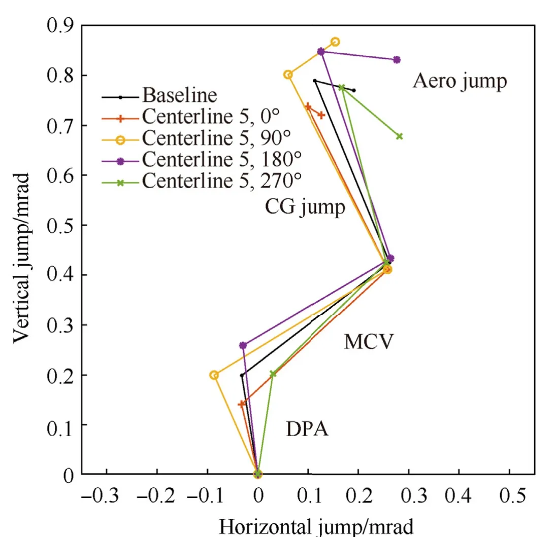
Fig.17.Jump comparison for the baseline barrel and Centerline 5 rotated to four positions with static jump components removed.
1.The order of the warp pointing angle contribution to total jump is equal to or greater than the order of magnitude of any other jump component.The effect of this centerline deviation acts mainly to shift projectile impact location in a manner exactly correlated to the angle of the centerline relative to the muzzle face,acting as a static shift.This is shown in Figs.14 and 16,being the most immediately obvious in Fig.16.
2.Beyond its influence as a static contributor to overall jump,warp affects barrel dynamics in such a way as to influence other jump components.This holds true for the rotation of a single centerline as well.Stated differently,if this was not true,the individual barrel jump plots would overlay exactly in Figs.15 and 17.
3.While warp does affect barrel dynamics and the associated jump,the standard deviation in the dynamic jump is small enough that it exists within common sighting device adjustment resolution.
Declaration of competing interest
The authors declare that they have no known competing financial interests or personal relationships that could have appeared to influence the work reported in this paper.
Acknowledgments
Sample barrels were supplied by Hardy Rifle Engineering Ltd.of Palmerston North,New Zealand.Barrel measurements were performed by Novacam Technologies Inc.of Pointe-Claire,Quebec,Canada.

- Defence Technology的其它文章
- Gliding arc plasma adjusting pre-combustion cracking products
- The role of tangential velocity in explosive initiation by fragment impact
- Prediction of concentration of toxic gases produced by detonation of commercial explosives by thermochemical equilibrium calculations
- Adaptive sliding mode control of modular self-reconfigurable spacecraft with time-delay estimation
- Modeling of unsupervised knowledge graph of events based on mutual information among neighbor domains and sparse representation
- Data-driven prediction of plate velocities and plate deformation of explosive reactive armor