
Influence of wettability in immiscible displacements with lattice Boltzmann method
2022-09-26 08:19:48ChenZHOUWenyuanWANGKexinCHENZejianCHENJongwonJUNGShuaiZHANGYunminCHENBateBATE
Chen ZHOU, Wen-yuan WANG, Ke-xin CHEN, Ze-jian CHEN, Jongwon JUNG, Shuai ZHANG, Yun-min CHEN, Bate BATE
Research Article
Influence of wettability in immiscible displacements with lattice Boltzmann method
Chen ZHOU, Wen-yuan WANG1, Ke-xin CHEN1, Ze-jian CHEN2, Jongwon JUNG3, Shuai ZHANG1, Yun-min CHEN1, Bate BATE
1Institute of Geotechnical Engineering, College of Civil Engineering and Architecture, Zhejiang University, Hangzhou 310058, China2Department of Civil and Environmental Engineering, The Hong Kong Polytechnic University, Kowloon, Hong Kong, China3School of Civil Engineering, Chungbuk National University, Cheongju, Chungbuk 28644, Korea
The role of wettability, often characterized by contact angle (), in two-phase immiscible phases displacement is not well understood. In this study, the color gradient lattice Boltzmann method (LBM), capable of maintaining the prescribed(from 0° to 180° at intervals of 10°) throughout the numerical simulations, was used to investigate the displacement patterns and displacement efficiency in a 2D porous medium. The capillary numbers () used were 0.01, 1, and 100, and the viscosity ratios () used were 0.1, 1, and 10. At=10, the saturation () had a bilinear relationship with, while for=0.1 and 1, the-?relationships were complicated by. A saturation contour in the--space was proposed to demonstrate the movement of a traditional 2D-??phase diagram withincrements. The value ofcontinued to increase after the breakthrough, and the final saturation (0.997) for the hydrophilic condition (=10°) was higher than that (0.673) for the hydrophobic condition (=170°).
Wettability; Porous media; Lattice Boltzmann method (LBM); Multiphase flow
1 Introduction
The displacement of two immiscible fluids in a porous medium is ubiquitous in nature, for example, the wetting front of rainfall in a soil slope (Sorbino and Nicotera, 2013), enhanced oil recovery (EOR) (Haugen et al., 2010; Muggeridge et al., 2014), geological CO2sequestration (Pruess, 2008; Hosseini et al., 2018), transport of non aqueous phase liquid (NAPL) in a contaminated underground site (Govindarajan et al., 2018), and underground storage of oil and gas (Shakeel et al., 2021). The displacement patterns, namely stable displacement, viscous fingering, and capillary fingering, primarily depend on the capillary numberand the viscosity ratiowhich are defined as
(1)
(2)
whereinvadingdenotes the dynamics viscosity of the invading fluid,indenotes the inlet velocity of the invading fluid, anddenotes the surface tension;invadingdenotes the density of the invading fluid, and is 1 in this study;invadingdenotes the kinematic viscosity of the invading fluid, anddefendingdenotes the kinematic viscosity of the defending fluid.
Wettability intuitively favors the improved displacement efficiency of the invading fluid. However, its effect on displacement efficiency as well as on displacement patterns is largely unknown. Wettability is defined by the contact angles at the pore scale and is measured by the relative permeability curves at the macroscopic scale (Mirzaei-Paiaman et al., 2022). Mora et al. (2021b) showed that a peak existed on the curves of saturation as a function of contact angles for viscous fingering with=0.01, illustrating that saturation sometimes does not increase with the increasing wettability. Lan et al. (2020) presented the phase diagram of displacement patterns in the-lgplane for<1 and captured the transitions of fluid invasion patterns with contact angles ranging from 45° to 135°. In porous media, such as that of underground reservoirs, wettability is an important factor that influences the flow patterns of fluids and eventually the macroscopic properties of multiphase flow, e.?g., permeability and saturation (Karabakal and Bagci, 2004; Fan et al., 2020). Experimental studies have revealed the occurrence of non-local, cooperative pore-filling events, and the improvement of final relative saturation as a result of the increased wettability of the invading fluid (Trojer et al., 2015; Zhao et al., 2016).
The mathematical models for multiphase flow in porous media (Karimi-Fard et al., 2006; Zhang et al., 2022), in the continuum scale, can provide a quantitative insight into the displacement process of a naturally fractured reservoir. Also, pore-scale numerical simulations can accurately describe the multiphase flow processes and capture heterogeneity, interconnectivity, and preferential flow paths. However, traditional computational fluid dynamics (CFD) methods which are based on the numerical solution of macroscopic variables in Navier-Stokes equations (NSEs) face challenges for dividing immiscible fluids by embedding physical interface tensions with a sophisticated interface reconstruction algorithm or an unphysical reinitialization process, such as volume-of-fluid (VOF), level set (LS) methods, and phase field (PF) methods (Hirt and Nichols, 1981; Badalassi et al., 2003; Sethian and Smereka, 2003). The difficulties of simulating wetting contact angles and contact line dynamics in complex pore media can be solved by the lattice Boltz mann method (LBM). LBM is a pseudo-molecular method based on mesoscopic kinetic Boltzmann equations consisting of particle distribution functions that have higher degrees of freedom where time, space, and velocity are separated. NSEs can be directly derived from the velocity space by evaluating the moments of distribution functions, which have lifting relationship with lattice Boltzmann parameters according to the multi-scale expansion analysis, such as the Chapman-Enskog (CE) expansion (Chen and Doolen, 1998; Lallemand and Luo, 2000; Xu et al., 2012). Its kinetic nature provides LBM with an advantage in simulating pore-scale multiphase flows and dealing with complex boundaries (Jiang et al., 2022). The color gradient model (CGM) (Gunstensen et al., 1991; Grunau et al., 1993; Leclaire et al., 2017; Li et al., 2021), one of the LBM multiphase models, has outstanding performance including strict mass, momentum conservation, a broad range of viscosity ratios, and accurate contact angles (Huang et al., 2014; Leclaire et al., 2016a; Xu et al., 2017; Zhao et al., 2019). In the CGM, the numerical interface thickness in the lattice unit is constant and is controlled by a set of parameters so that, during the time evolution of the simulation, the two-phase interfaces automatically converge without diffusing as in the pseudopotential model. Instead of setting a fictitious density in the solid boundary lattice (Latva-Kokko and Rothman, 2005), the desired contact angle can be achieved in the proposed contact angle algorithm (Leclaire et al., 2016a; Xu et al., 2017), which is suitable for a complex pore scale structure.
In this study, LBM with the color gradient model is used to study the effect of wettability in immiscible two-phase flows. A full range of contact angles from 0° to 180° with 10° intervals, is simulated with the viscosity ratiosin the range of [0.1, 10] and the capillary numberin the range of [0.01, 100]. The displacement patterns, displacement ratios, and velo city contours are observed and compared with the existing literature.
2 Methods
2.1 Immiscible color gradient lattice Boltzmann model
In the CGM, immiscible two-phase fluids are divided into two colors, red and blue, which respectively are represented by red and blue distribution functions,=r or b denoting the color of the fluid, and=0, 1, 2, …, 8 denoting the direction of each distribution function. The fundamental theory of the distribution function and the LBM is provided in Section S1 of the electronic supplementary materials (ESM).
The CGM-LBM equation is:
(3)
wheredenotes the spatial location,denotes the lattice velocity vector,denotes the time interval,deno tes the time, anddenotes the total collision operator:
(4)
which includes a single-phase collision operator, a perturbation collision operator, and a recoloring collision operator. As a result, the original collision is broken down from one step to three steps: single-phase collision, perturbation, and recoloring. Similarly, the separated distribution function still requires that:
(5)
(6)
(7)
whereρdenotes the density of fluid,denotes the total density of fluid, anddenotes velocity for the color-blind distribution function. In the immiscible two-phase fluid system, the order parameter is usually used to represent different phases and to capture the interface. In the CGM, the phase field is represented as:
(8)
where=1 represents pure red fluid, while=-1 represents pure blue fluid.andrepresent the reference densities of the red and blue fluids, respectively.
The multiple relax time (MRT) operator is often used to solve the single-phase collision in the interest of the stability and robustness of the numerical calculation. Firstly, the distribution functions are projected to the moment space with the transformation matrix and then the single-phase collision is carried out in the moment space according to the diagonal matrixformed by the relaxation coefficient. Finally, the distribution functions are received under the inverse transformation of moment:
(9)
(10)
(11)
(12)
whererandbdenote the viscosities of the red and blue fluids, respectively,=δ/δ, δdenotes the lattice spacing.
The perturbation operator is derived from the energy definition of surface tension by Chapman-Enskog expansion:
(13)
(14)
(15)
where=A.
Depending on the color gradient, the perturbation operator redistributes the mass near the interface, it decreases along the lattice link parallel to the interface and increases along the lattice link perpendicular to the interface while conserving the total mass and total momentum inside the individual lattice. The distribution function determines an upper limit on the redistribution based on the surface tension and phase field gradient. In addition, the ratio of redistribution to the mass in the lattice link direction is determined by the angle of the phase field gradient to the lattice link. To ensure that the lattice Boltzmann equation is derived correctly after adding the perturbation operator, it is required that:
(16)
Then the distribution function becomes:
(17)
The recoloring operator proposed by Latva-Kokko is used to facilitate phase separation, in order to maintain an appropriate interface:
(18)
(19)
wherecontrols the interface thickness. To ensure the stability and accuracy of the values,is set to 0.99, andφis the angle between the color gradientand the lattice velocity.
The above operator allows a moderate mixture of red and blue fluids in the tangential direction of the interface while preserving the symmetry of the color distribution relative to the color gradient (Latva-Kokko and Rothman, 2005). Thus, it can further reduce the pseudo-velocity and eliminate the lattice pinning effect generated by the original recoloring operator proposed by Gunstensen et al. (1991).
After recoloring, the distribution function performs streaming steps:
(20)
Finally, the density and velocity within the time step (+δ) can be obtained by Eqs. (5)–(7).
2.2 Boundary condition
There are numerous boundary conditions for LBM to guarantee the preservation of stability and accuracy to different extents according to simulation requirements. The general computational fluid mechanics include the Dirichlet boundary, Neumann boundary, and Robin boundary, which are accomplished by controlling the distribution function within the boundary lattice for LBM. For simplicity of the simulation, through half-way bounce back (no-slip boundary condition), mass and momentum are conserved strictly in every time step near the boundary. Similarly, by allocating the distribution function, a constant flow velocity at the inlet and the Neumann boundary condition is achieved at the outlet to ensure steady displacement.
For the immiscible two-phase fluid, wettability is characterized by the contact angle. LBM introduces a virtual mass or virtual phase field at the solid boundary to describe the contact angle, considered as the forces between mesoscopic virtual particles. However, this leads to nonphysical mass transfer at the wetting boundary (Leclaire et al., 2016b). Thus, setting the phase field gradientdirectly at the three-phase contact lines guarantees mass conservation, which is more intuitive and accurate (Xu et al., 2017). This boundary condition is briefly introduced below and includes four steps. Firstly, the phase field at the solid node adjacent to the fluid can be evaluated by approximating withof its nearest fluid nodes:
(21)
where(+δ) equals 0 or 1 for a solid or fluid node, respectively. Secondly, the predicted value of phase field gradient′ is calculated by Eq. (14) and then the estimated unit normal vector of the phase interface is denoted by′=′/|′|. Thirdly, the theoretical unit normal vectors of the phase interface,1and2, are computed by the wall normal vectorsand the contact angle:
(22)
In order to obtain the exact unit normal vector of the phase interface adjacent to at least one solid node,cis selected by:
(23)
where1=|′-1| and2=|′-2|. Finally, the orientation of the phase field gradient is modified to achieve the desired contact angle by
(24)
Based on Eqs. (22)?–?(24), this wetting boundary condition accurately and directly assigns contact angles for arbitrary geometries with smaller spurious currents compared to the widely used fictitious density boundary condition.
3 Static contact angle and fingering simulation
3.1 Verification of static contact angle algorithm
Depending on the difference in wettability, a set of static droplets on the horizontal surface present different static contact angles. To verify the accuracy of the contact angle setting method, a square droplet of 20 lu×20 lu (lattice unit) was initially placed on the bottom wall in a domain of 60 lu×30 lu, and the droplet shapes in the equilibrium state were obtained after 50000 time steps (Fig. 1). The halfway bounce-back method was used at the surrounding walls to obtain the no-slip boundary condition. The parametercontrolling the interface tension was chosen to be 0.01 and the viscosities of both fluids were 0.8. The numerical simulations present the wetting, middle-wetting, and non-wetting boundary conditions of the droplet with three given contact angles. This intuitively verifies the accuracy and convenience of the proposed algorithm without adjusting tedious parameters.
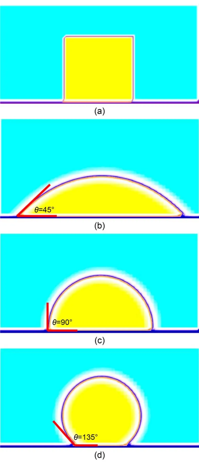
Fig. 1 Shapes of droplets resting on a flat surface: (a) initial droplet shapes (yellow color) and (b)?–?(d) equilibrium droplet shapes with prescribed wetting angles of 45°, 90°, and 135°, respectively. References to color refer to the online version of this figure
3.2 Flow patterns in a single channel
It is well known that the invading fluid will exhibit a growing fingering effect penetrating into the defending fluid instead of pushing it, especially at viscosity ratio?1. The effect of static contact angles on the finger penetration in a channel has been studied using the Shan-Chen pseudopotential multiphase model (Kang et al., 2004). Therefore, in this section, we de monstrate only the application of the presented color gradient model for two-phase one-channel displacement.
As shown in Figs. 2 and 3, the computational domain is 160 lu×40 lu, and the invading fluid with contact angle=90° is put in the left section of the domain. For the stable displacement case, the viscosity ratiois set to 1 withinvading=0.1 anddefending=0.1. For the viscous fingering case, the viscosity ratiois 0.01 withinvading=0.005 anddefending=0.5. The upper and lower walls are assigned a no-slip boundary condition with the half-way bounce-back method. The left wall is a velocity inlet boundary with the Zou-He scheme (Zou and He, 1997). The right wall is an outflow boundary with the Neumann boundary condition, which is suitable for two-phase flows (Lou et al., 2013). To avoid boundary effects, a Poiseuille velocity profile with the maximum valuein max=0.01 is enforced at the inlet. In both cases, the parameter controlling the interface tension is fixed at=0.01.
Stable displacement (Fig. 2) occurs with an intermediate viscosity ratio=1 and a low inlet velocityin max=0.01. The two-phase interfaces (Figs. 2a???2d) are slightly bent and no finger is formed. The slip of the contact lines keeps up with the front of the displacement, so that all the defending fluid can be almost displaced, which can be considered as the optimal displacement result.
However, the viscous or capillary fingering occurs (Fig. 3) at a low viscosity ratio?1, which is referred to as a Saffman-Taylor instability (Tabeling et al., 1987). The finger is formed at the driving velocity, but the finger width and length cannot remain constant over time as a stable displacement. It is also obvious that the front of the finger cannot be consistent with the slip of contact lines, and the length of the two-phase interface continually increases with the evolution of the fingering process. We can see that the front part of the finger is wider than the back part, and the finger has the tendency to snap-off (Fig. 3d). Apparently, the viscous fingering effect could lead to incomplete displacement or lower recovery efficiency.
The above simulation results show that the proposed color gradient LBM can exactly reproduce the wetting contact angles and the basic displacement patterns, namely stable and viscous fingering with different viscosity ratios. This provides the numerical basis for the subsequent porous media simulations.

Fig. 2 Finger evolution for viscosity ratio M=1, with contact angle θ=90°, changing with time step t: (a) t=0; (b) t=2000; (c) t=4000; (d) t=6000
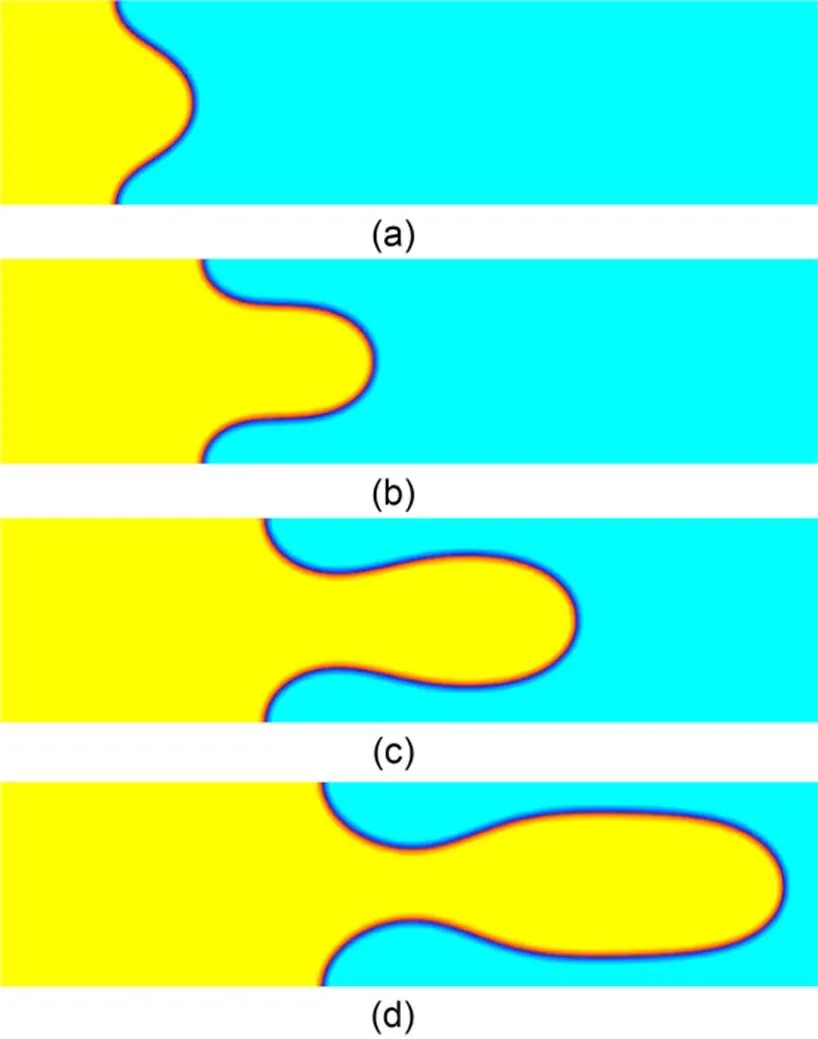
Fig. 3 Finger evolution for viscosity ratio M=0.01, with contact angle θ=90°, changing with time step t: (a) t=0; (b) t=2000; (c) t=4000; (d) t=6000
4 Displacement simulation in a porous medium
4.1 Model and simulation conditions
In order to achieve the stable displacement and viscous fingering effects, capillary numbersof 0.01, 1, 100, viscosity ratiosof 0.1, 1, 10, and contact angles ranging from 0° to 180° at intervals of 10° were used in the numerical simulation (Table 1). A simplified model of a porous medium was generated in a 2D region with a size of 200 lu100 lu (Fig. 4). The porous medium was constructed in the middle domain with a size of 100 lu100 lu, where non-overlapping particles were dropped randomly (Huang et al., 2014). The outer diameters of these randomly distributed particles ranged from 5 lu to 10 lu, and the minimum gap between any two particles was set to be 5 lu. The shapes of particles with outer diameters of 5 lu were set as squares and the shapes of other particles were set as circles. As shown in Fig. 4, the pore space in the model was initially saturated with the defending fluid, and the other fluid invaded from the left. The left side of the domain was the inlet with a fixed velocityinfor which the Zou-He method (Zou and He, 1997) was adopted to implement the exact velocity by redistributing the unknown distribution function. The right side was the outlet with outflow boundary conditions (Junk and Yang, 2008). The top and bottom sides of the domain were assigned the non-slip boundary described by half-way bounce back for LBM. To quantify the displacement efficiency, the relative saturation(Mora et al., 2021a) is defined as
(25)
(26)
whereSrepresents the saturation of the invading fluid at breakthrough (Fig. 4). The subscriptdenotes the contact angle of the invading fluid.invading,defending, andinterfacerespectively represent the total lattice numbers of the invading fluid, defending fluid, and interface at breakthrough in the porous domain (betweenandin Fig. 4) where the displacement took place.
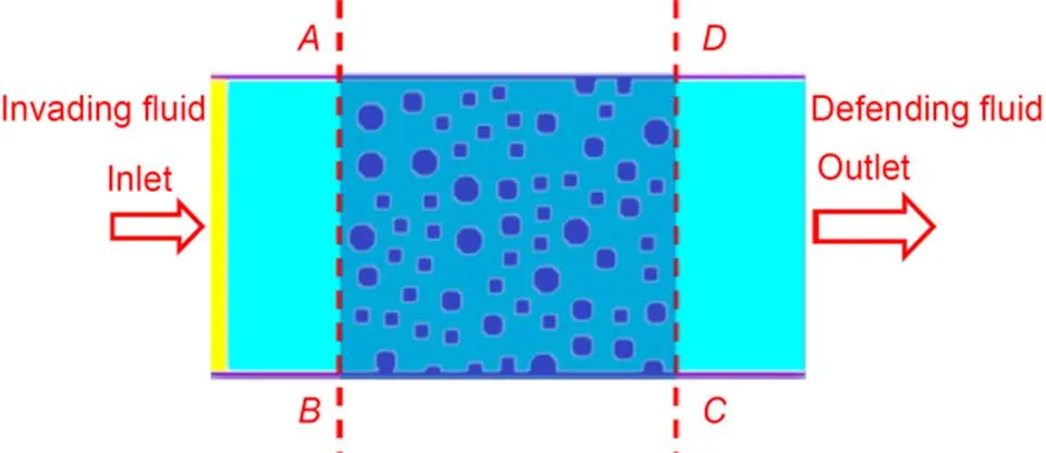
Fig. 4 Initial two-phase and solid distribution in the model porous medium: the yellow, light blue, and the dark blue portions represent the invading fluid, defending fluid, and solid, respectively. References to color refer to the online version of this figure
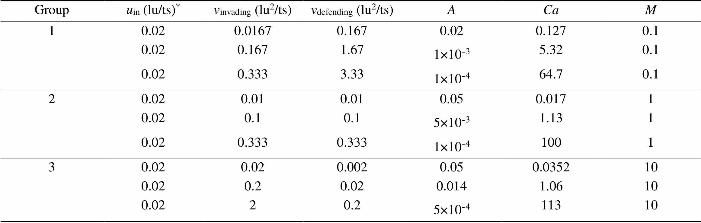
Table 1 Simulation parameters divided by viscosity ratio M in the three groups
*andrefer to LBM lattice unit and time step, respectively (Sukop and Or, 2004)
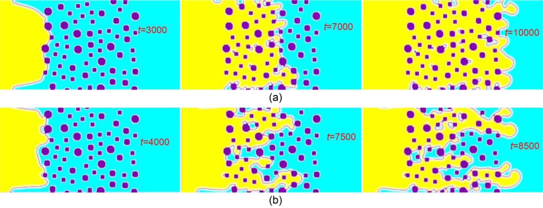
Fig. 5 Evolution of the typical displacement processes with time step t: (a) stable displacement, Ca=1.06, M=10, and θ=90°; (b) viscous fingering, Ca=5.32, M=1, and θ=90°, the invading fluid advanced to the right
4.2 Typical displacement patterns
The typical results of a stable displacement in the porous medium (Fig. 4) are shown in Fig. 5a, where=1.06,=10 (Table 1), and=90°?. The front of the invading fluid proceeded relatively uniformly toward the defending fluid as time passed. The typical results of a preferential flow pattern in the porous medium (Fig. 4) are shown in Fig. 5b, where=5.32,=1 (Table 1), and=90°. As time progressed, the viscous fingering at the top and the bottom portions advanced faster than the remaining portions along the advancing front. In both cases, the prescribed contact angles at the solid-fluid interface were maintained throughout the test. The mass of the defending fluid was also conserved at the solid boundary due to the wetting boundary algorithm in Section 2.3.
4.3 Displacement and flow patterns at breakthrough
The simulation results (Figs. 7 and 8) in the form of a-phase diagram (Lenormand et al., 1988) indicate the flow pattern transitions from viscous fingering to stable displacement whenincreases. The mean final saturation of the invading fluid increases from 0.435 to 0.829, and the viscosity ratio is the dominant factor that divides the three parts in the-diagram. The range of saturations is almost the same as that of Huang et al. (2014) where the range is 0.81?–?0.86 for stable displacement and is 0.31?–?0.46 for viscous fingering.
4.3.1Effects of contact angles on the displacement patterns
It is generally accepted that as the contact angle increases, the displacement pattern evolves from strong imbibition to weak imbibition and weak drainage to strong drainage (Zhao et al., 2016). As the contact angle increases from 0° to 180° (Fig. 6), the invading front transforms from broad with few branches to narrow with many branches, and the quantity of the pinned pockets of the defending fluid around the solid particles increases. In practice, the wetting contact angles 0°?–?10° constitute an extreme condition which result in the numerical errors. Therefore, these contact angles were excluded in this study. For each-pair, there was almost an "optimal" contact angle at which the maximum Δ, namely a peak of the Δ-curve, was achieved (Mora et al., 2021a). These optimal contact angles ranged fromto, which were all hydrophilic (<90°). For the displacement patterns at the optimal angles (Fig. 7), as the viscosity ratioincreased, the fronts transformed from tree-like patterns (=0.1) to rounded and broader fingers (=1), and eventually to the ideal pattern of stable displacement (=10) with fronts advancing abreast and near non-existence of trapped pockets of the defending fluid. On the other hand, for each-pair, the minimum Δwas reached at the "least optimal" contact angle ranging from 170° to 180°, opposite to the "optimal" contact angles, which were all hydrophobic (>90°). The displacement patterns with the least optimal contact angles (Fig. 8) presented thin fingers, branches, and many pockets of defending fluid in the medium. It is worth noting that even the least optimal contact angles are not all 180°, which can be considered as the extreme conditions of the numerical simulations.
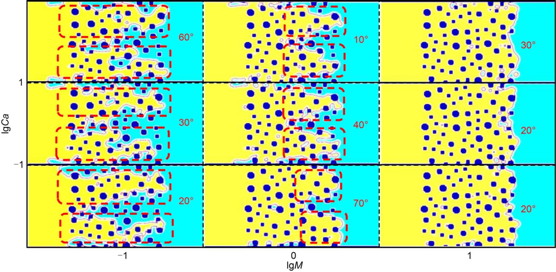
Fig. 7 Displacement patterns at breakthrough in the form of a M-Ca phase diagram, when the saturation difference ΔS reaches the maximum with the optimal contact angles. The advancing fronts are boxed by dashed lines
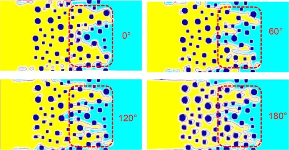
Fig. 6 Flow patterns for M=1 and Ca=100 for contact angles of 0°, 60°, 120°, and 180°. The displacement fronts are marked with dashed lines
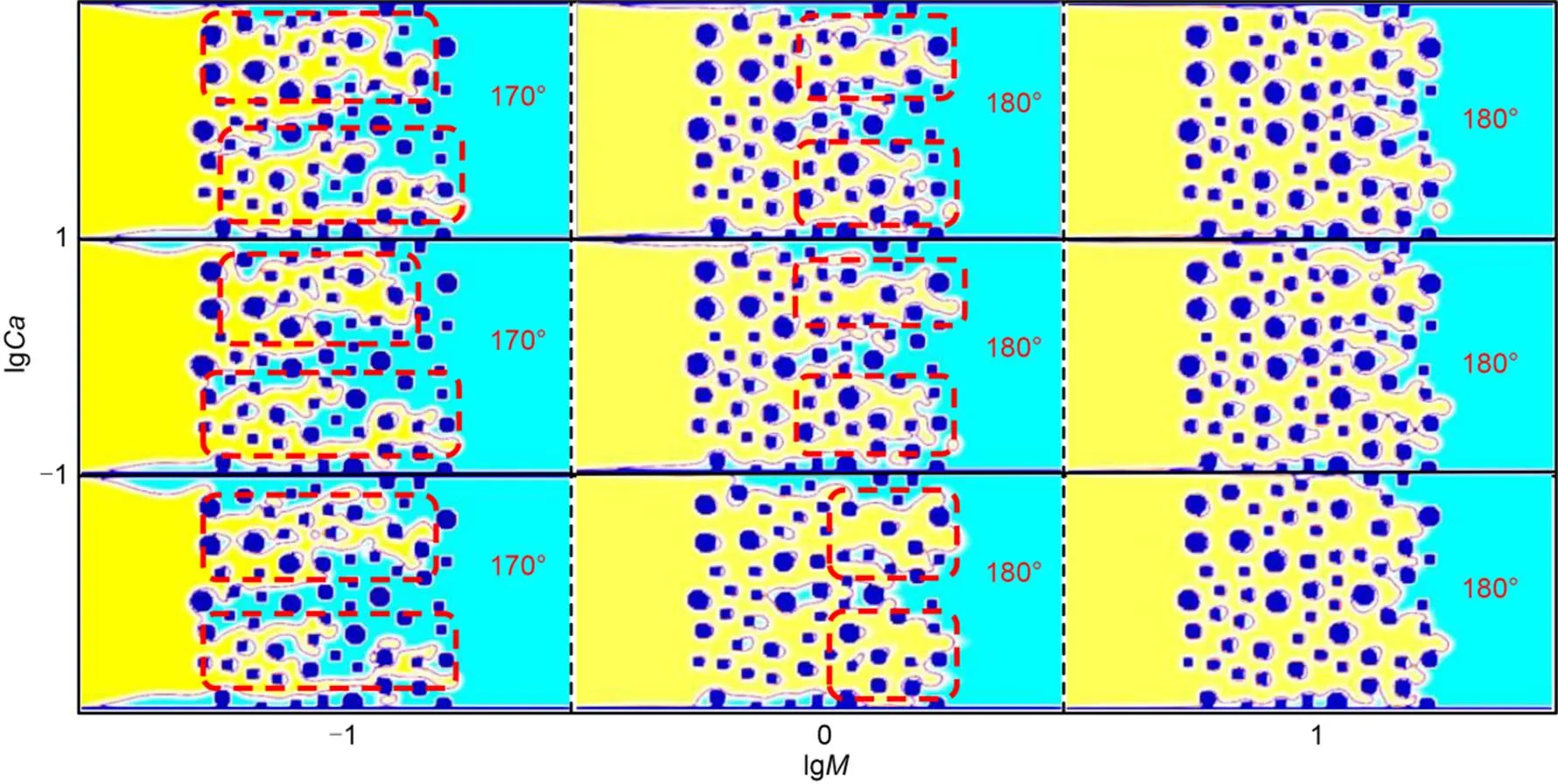
Fig. 8 Displacement patterns at breakthrough in the form of a M-Ca phase diagram, when the saturation difference ΔS minimizes with the least optimal contact angles. The advancing fronts are boxed by dashed lines
4.3.2Effects of wettability on Δ
As the wettability decreased, as quantified by the contact angle increasing from 0° to 180°, the saturation of the displacement process, denoted by Δ, generally decreased. This suggests the hydrophilic fluid invading the solid matrix is favorable for high displacement efficiency. Local Δpeaks at contact angles of 20°?–?70° were sometimes higher than Δwith a highly hydrophilic invading fluid (Fig. 9).
For instance, when=1 and=0.017, the Δmaximum value of 0.29 at=70° was much higher than Δat=10° (0.16). This observation agrees with prior studies (Zhao et al., 2019), which reported that the contact angle of 60°, representing the weak imbibition wettability condition, yielded the highest displacement efficiency. However, the final saturationfinalin strong imbibition due to the early breakthrough by the corner flow (Zhao et al., 2016) is only half that of thein weak imbibition.
A closer inspection revealed that the Δdecrement withwas generally bilinear, including a gentle Δdrop sector at<[80°, 120°], and a steeper Δdrop sector at>[80°, 120°], at theandranges investigated in this study. In other words, an increment in hydrophobicity (>90°) led to poor displacement efficiency. This generally agrees with prior studies (Armstrong et al., 2021; Bakhshian et al., 2021). In contrast, hydrophilicity (<90°) was not necessarily monotonically correlated with displacement efficiency, especially at lowand.
4.3.3Effects of capillary numbers and viscosity ratios on Δ
The capillary numberreflects velocity, viscosity, and surface tension, the effects of which on the displacement efficiency are quantified by Δ. Increase inprimarily leads to an increase in Δin general. As shown in Fig 9, this trend was apparent at low(=0.1) and was less significant at highervalues (=10). This observation suggests that the displacement efficiency with invading fluids of low viscosity highly depends on the velocity or the injecting flow rate, which demands high pressure capacity of the equipment and high energy consumption, while the displacement efficiency with invading fluids of high viscosity does not depend on the velocity as much. At hydrophobic interfaces (>90°), this trend was clearly hierarchical; while at hydrophilic interfaces (<90°), this trend was distinct, often disturbed by local peaks and valleys of Δ.
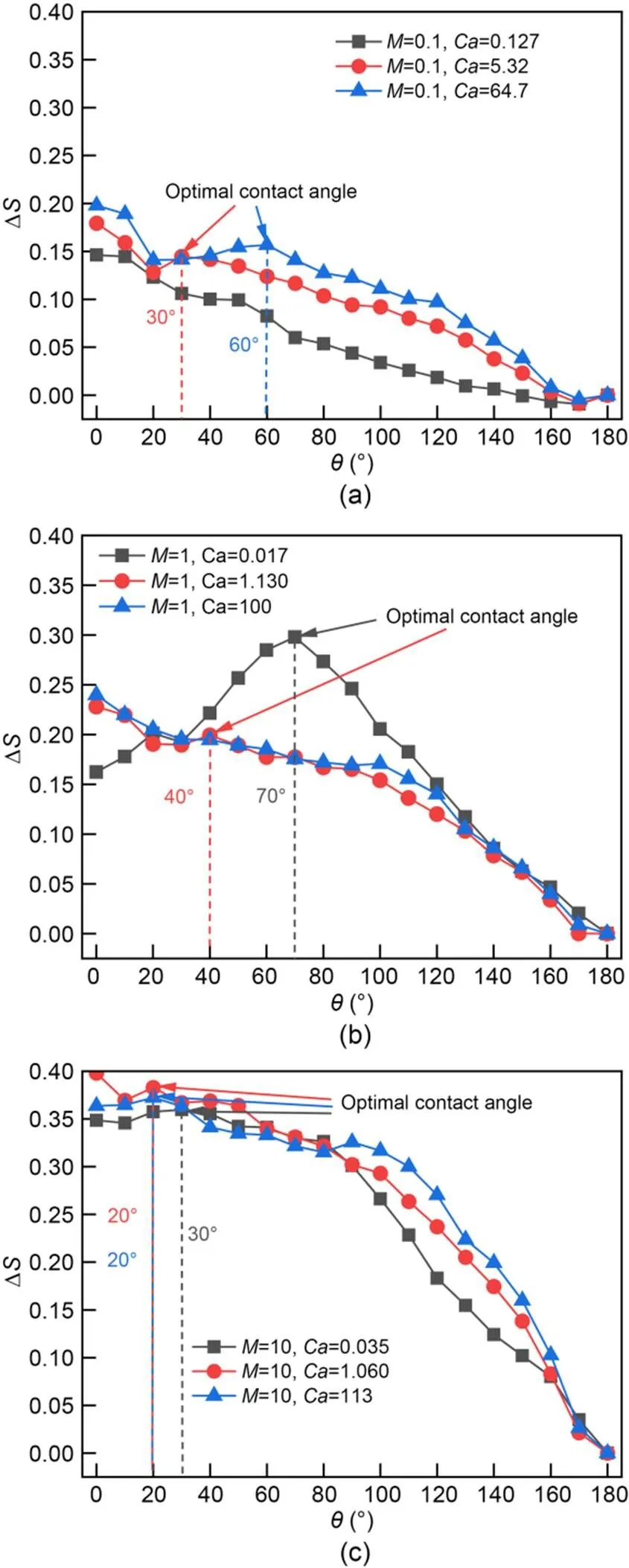
Fig. 9 ΔS-θ curves for M=0.1 (a), M=1 (b), and M=10 (c). The optimal contact angles are chosen in the range of θ>10°
For=1 (Fig. 9b), the Δ-?curve reached a much higher peak at=70° for=0.017 than that for othervalues. The contact angle of the convex hill in this curve ranged from 30° to 100°, in the region of weak imbibition and neutral wettability. At=0.017, the invading fluid advanced via contact-line motion and the displacement was almost complete, therefore the effect of contact angles dominated the displacement efficiency. However, at=1.130 and 100, the viscous forces dominated the capillary forces and the invading fluid formed fingers that advanced along the center of the pore space, weakening the impact of contact angles. In the experiments of Zhao et al. (2016), the difference of saturation between weak imbibition (=60°) and strong drainage (=150°) at smallvalues was much higher than that at largevalues, which was consistent with our study.
Asincreased from 0.1 to 1 and then to 10, Δgenerally increased. It is clear that the displacement of an invading fluid with high viscosity normally results in higher displacement efficiency. Although not shown in the range ofandin this study, which essentially indicated either viscous fingering or stable displacement patterns, it is must be born in mind that at very lowvalues (e.?g.<10-4), capillary fingering began to dominate the displacement patterns, which could result in low displacement efficiency (Lan et al., 2020).
4.3.4Bilinear fitting of-curves
As illustrated in Fig. 10, when=10, the trend of-?was divided into two parts by=90°. Bakhshian et al. (2021) described the corrections ofat breakthrough under the weak drainage and weak imbibition when>1 and the pore-size distribution of porous media was unimodal. Herein, an improved linear relationship is proposed:
(27)
Fig. 10 S-θ for M=10: the linear fitting includes all Ca
where90°represents the saturation of=90 at breakthrough, andis the orientation angle of the pore.was originally computed as tan=1-t/b, wheretwas the average pore throat size, andbwas the average pore body size. However, it was limited to the range of 0°?–?45° and its value only depended on the pore size, so that two trends of the drainage and imbibition could not be distinguished. Therefore, in order to contain the two stages,is separated at=90° intoβ<90°andβ>90°whose values are achieved by linear fitting.
Unlike the case of=10, for=1 and 0.1, a uniform fitting was not representative of the-relationship without considering thevalues. This demonstrated the complicated nature of the displacement process, where the displacement efficiency is a function of,, and.
4.3.5in the--space
Based on the ranges of,, andin this study, a 3D contour was plotted to encompass thevalues in the stable displacement region and viscous fingering regions (Fig. 11). On the local scale, there is fluctuation in/displacement efficiency; however, on a large scale, i.?e.,orspanning orders of magnitude, the essential trends of variation with,, andcan be captured, as rendered in Fig. 11.
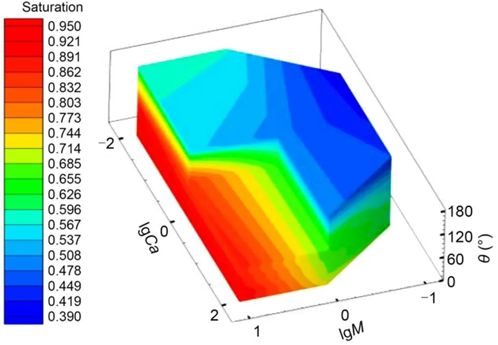
Fig. 11 M-Ca-θ 3D rendition of S: the part of lgM>0, lgCa>0, and θ>90° is excluded to illustrate the inside contour
Each iso-?slice plane (Fig. 12) represents a traditional-diagram (Lenormand et al., 1988), but the stable displacement, viscous fingering, and the transition regions can still be identified. A series of iso-?planes demonstrated the "moving-target" nature of the-chart, which can explain the varied zones of "stable displacement" (which was often accompanied by a high saturation of invading fluid and a uniform advancing front of the invading fluid) as well as the moving "viscous fingering" zone (which was often accompanied by thick fingering and a few branches of the invading fluid, and intermediate to low degree of saturation of the invading fluid).
The-lines at givenandvalues could also be obtained by slicing the 3D contour with the prescribedandvalues. To obtain a high displacement efficiency, the wettability, and the most cost-effective parameters from viscosity, velocity, and surface tension, could be identified and adjusted, so as to obtain highvalues in an economic way.
In order to quantify the-?-?space, the fitted quadratic polynomial equations of iso-saturation surfaces (i.?e.,=constant) were presented as follows:
(28)
where00,01,10,20,11, and02are fitting coefficients for a given constantvalue (e.?g.,=0.8), as tabulated in Table 2. The iso-saturation surfaces provide a quantitative relationship between,, and, for a given displacement saturation.
It should be noted that only limitedandranges were studied, and the 3D contour should be expanded to cover more-sceneries for engineering implementation. We are also aware that during the displacement process, shear-thinning or shear-thickening could occur locally in the solid matrix, which decreases or increases thevalues, and an "animated" version of the 3D contour should be created.
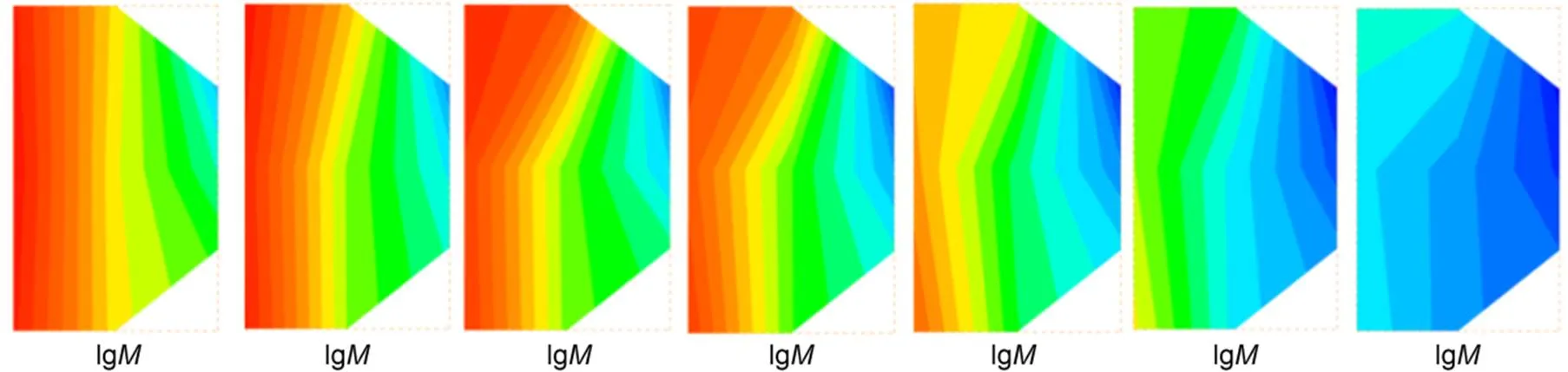
Fig. 12 Slices along contact angles θ: from left to right, θ=0°, 30°, 60°, 90°, 120°, 150°, and 180°
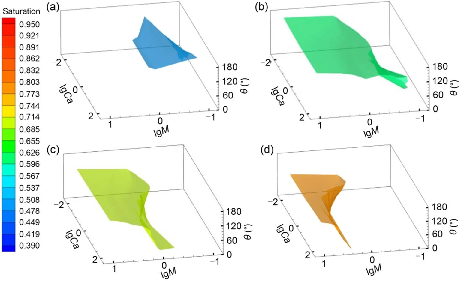
Fig. 13 Iso-S surfaces of M-Ca-θ 3D diagram: (a) S=0.5; (b) S=0.6; (c) S=0.7; (d) S=0.8
Table 2 Fitting coefficients of the iso-S surfaces
It is also important that under a hypergravity condition, such as in a geotechnical centrifuge, the velocity could be amplified due to the scaling rules. Correspondingly, thevalue could increase, resulting in higher displacement efficiency than the 1(gravitational acceleration) condition, such as in a rainfall-induced slope failure simulation, whereas the dominant capillary fingering under 1condition could be shifted towards stable displacement. Further investigation of each specific case is warranted.
4.3.6Velocity contours
For=10 (Figs. 14 and 15), the maximum velocity occurred in the wide and continuous pore throats. However, for=0.1, the maximum velocity was at the front of the preferential flow, which coincided with the simulation results of Mora et al. (2021b) in that, for=0.01, the maximum velocity was at the viscous fingers. As for=1, the maximum velocity occurred both in the preferential fingering region and in-between fingers (Fig. 14h). For=10, given the lack of fingering flow, the maximum velocity occurred sporadically throughout the medium. By contrast,in the simulated range (10-2to) had negligible effects on the velocity distribution and the location where maximum velocity occurs (Figs. 14 and 15). In addition, the contact angles only locally changed the positions of maximum velocity (Figs. 14d and 15d), with the global flow velocity left unaffected. Similarly, Mora et al. (2021b) found that under the same-pair, the velocity flow paths were almost identical for=0°, 90°, or 180°.
Fig. 14 Fluid velocity fields of the displacement patterns at the optimal angles (Fig. 8): the areas of fingering are boxed by dashed lines; the areas circled by dot-dashed lines represent the maximum velocity regions: (a–i) represent the fluid velocity fields corresponding to M-Ca-

Fig. 15 Fluid velocity fields of the displacement patterns at the least optimal angles (Fig. 9): the areas of fingering are boxed by dashed lines; the areas circled by dot-dashed lines represent the maximum velocity regions: (a–i) represent the fluid velocity fields corresponding to M-Ca-
4.4 Development of displacement and flow after breakthrough
After breakthrough, further evolutions of displacement efficiency and flow patterns for the viscous fingering were investigated under the conditions of=0.1,=0.127, and=10°, 170°. The final saturationfinal, defined as the asymptotic saturation value after breakthrough, was high (0.997) for=10° (Fig. 16), and was only 0.673 for=170°. Similarly, Fan et al. (2020) observed that, based on the waterflooding curves in a sandstone sample,decreased with the contact angle increasing from 45° to 135°. Moreover, both the saturation curves of Fan et al. (2020) and Fig. 14 indicated that, no matter what the wetting condition was, the time between the breakthrough and final saturation was nearly five times more than that between the initial invasion and the breakthrough. By contrast, Mora et al. (2021b) observed that the final saturations for the perfectly wetting (=0°) and non-wetting (=180°) conditions were almost identical, which indicated the complex nature of the effects of contact angles on the fluid displacement process.

Fig. 16 Curves of the saturation versus time for contact angle θ=10° and 170°, viscosity ratio M=0.1, and capillary number Ca=0.127: Sbreak is the saturation at breakthrough and Sfinal is the final saturation after breakthrough
For strong imbibition (=10°), the corner flow (Golmohammadi et al., 2021) emerged at the bottom edge of the porous medium before breakthrough, contributing to the long band-like clusters of trapped defending fluid (Fig. 17c). Similarly, in the experiments and numerical simulations of Levache and Bartolo (2014), the corner flow invaded along the top and bottom surfaces with thin films for≈7°. After breakthrough, the corner flow persistently crawled forward along the solid boundary and the trapped clusters of the defending fluid were gradually displaced by the wetting invading fluid (Figs. 17d?–?17i). With the evolution of invasion, the width of fingers increased, and the displacement patterns developed into the stable displacement.
Under=170°, the invading fluid front advanced along the center among the adjacent particles (Fig. 18). This resulted in the trapped ganglia-like clusters of the defending fluid. As the invading fluid continually filled the center of the pore throat, the defending fluid in the trapped area snapped off (Singh et al., 2017; Bakhshian et al., 2020). After breakthrough, the trapped clusters of the defending fluid clung to the solid columns and remained there, while others were gradually displaced (Figs. 18c?–?18i). Finally, the fingering developed into stable displacement, and the pinned defending fluid bubbles were distributed in isolation at the rear of each solid particle along the inlet velocity (Fig. 18i). Themaintained at 170° contributed to the displacement pattern of local cooperative filling (Cieplak and Robbins, 1990) and led to many trapped bubbles. The velocity fields for=170° (Fig. 19) showed that, after breakthrough, the branches of the maximum velocity in the fingers gradually increased with the increasing preferential flow paths. Furthermore, as the width of fingers increased, the width of the maximum velocity channels also increased. Eventually, the maximum velocity channels were uniformly distributed in the broad pore channels throughout the porous media (Fig. 19i).
Fig. 17 Flow patterns versus time step t for contact angle θ=10°, viscosity ratio M=0.1, and capillary number Ca=0.127: the areas boxed by dashed lines are the evolving fingers; the corner flow is circled by the dot dashed lines: (a?–?i) represent the flow pattens versus time step t
Fig. 18 Flow patterns versus time step t for contact angle θ=170°, viscosity ratio M=0.1, and capillary number Ca=0.127: the areas boxed by dashed lines are the evolving fingers: (a–i) represent the flow pattens versus time step t

Fig. 19 Velocity fields corresponding to Fig. 17: (a–i) represent the fluid velocity fields versus time step t
5 Conclusions
This study investigated the effect of wettability on the immiscible displacement with LBM simulation. The following findings were established:
1. As the contact angles of the invading fluid increased from 0° to 180°, the invading front transformed from broad branches to narrow branches, and the number of the pinned pockets of defending fluid increased. The viscosity ratioincreasing from 0.1 to 10 caused the displacement patterns to be transformed from viscous fingering into stable displacement. However, theincreasing from 0.017 to 100 could not dominate the displacement patterns. At the optimal angles, for the=10, the ideal displacement patterns were obtained.
2. In general, as the contact angleincreased, the displacement efficiency decreased. The local Δpeaks at contact angles of 20°?–?70° were sometimes higher than the Δat<20°. The increase ofandalso led to an increase in Δ. When=10, the-?relationship (Eq. (27)) was bilinear, divided by=90°.
3. The saturation contour for the invading phase was summarized in an--3D space, which is an expansion of the conventional-diagram. The iso-?slice planes captured and illustrated the "moving-target" nature of the traditional-diagram.
4. The maximum velocity emerged in the preferential flow paths for the viscous fingers. However, for stable displacement, the maximum velocity tended to distribute evenly across the porous medium.
5. After breakthrough, for=0.1 and=0.127, the corner flow emerged in the edge under=10°, which was gradually merged with preferential fingers to yield a high displacement efficiency (=0.997). However, for a hydrophobic contact angle (=170°), the trapped clusters of the defending fluid were pinned at the rear of solid particles, leading to a displacement efficiency of only 0.673.
It was noted that static contact angles were assumed, while the actual contact angles also depend on surface roughness, chemical condition, shear induced thinning, or thickening, and receding, or intruding dynamics. Thus, further investigations accounting for the above factors are warranted.
This work is supported by the Basic Science Center Program for Multiphase Evolution in Hypergravity of the National Natural Science Foundation of China (No. 51988101), and the National Natural Science Foundation of China (Nos. 42177118 and 51779219). Financial support from the Overseas Expertise Introduction Center for Discipline Innovation (No. B18047) is also acknowledged.
Chen ZHOU established the numerical simulation and wrote the first draft of the manuscript. Wen-yuan WANG and Ke-xin CHEN helped to analyze the results. Ze-jian CHEN, Jongwon JUNG, Shuai ZHANG, and Yun-min CHEN provided important suggestions on the improvement of the study. Bate BATE revised and edited the final version.
Chen ZHOU, Wen-yuan WANG, Ke-xin CHEN, Ze-jian CHEN, Jongwon JUNG, Shuai ZHANG, Yun-min CHEN, and Bate BATE declare that they have no conflict of interest.
Armstrong RT, Sun CH, Mostaghimi P, et al., 2021. Multiscale characterization of wettability in porous media., 140(1):215-240. https://doi.org/10.1007/s11242-021-01615-0
Badalassi VE, Ceniceros HD, Banerjee S, 2003. Computation of multiphase systems with phase field models., 190(2):371-397. https://doi.org/10.1016/s0021-9991(03)00280-8
Bakhshian S, Rabbani HS, Hosseini SA, et al., 2020. New insights into complex interactions between heterogeneity and wettability influencing two?‐phase flow in porous media., 47(14):e2020GL088187. https://doi.org/10.1029/2020gl088187
Bakhshian S, Rabbani HS, Shokri N, 2021. Physics-driven investigation of wettability effects on two-phase flow in natural porous media: recent advances, new insights, and future perspectives., 140(1):85-106. https://doi.org/10.1007/s11242-021-01597-z
Chen SY, Doolen GD, 1998. Lattice Boltzmann method for fluid flows., 30(1):329-364. https://doi.org/10.1146/annurev.fluid.30.1.329
Cieplak M, Robbins MO, 1990. Influence of contact angle on quasistatic fluid invasion of porous media., 41(16):11508-11521. https://doi.org/10.1103/physrevb.41.11508
Fan M, McClure JE, Armstrong RT, et al., 2020. Influence of clay wettability alteration on relative permeability., 47(18):e2020GL088545. https://doi.org/10.1029/2020gl088545
Golmohammadi S, Ding Y, Kuechler M, et al., 2021. Impact of wettability and gravity on fluid displacement and trapping in representative 2D micromodels of porous media (2D sand analogs)., 57(10):e2021WR029908. https://doi.org/10.1029/2021WR029908
Govindarajan D, Deshpande AP, Raghunathan R, 2018. Enhanced mobility of non aqueous phase liquid (NAPL) during drying of wet sand., 209:1-13. https://doi.org/10.1016/j.jconhyd.2017.12.005
Grunau D, Chen SY, Eggert K, 1993. A lattice Boltzmann model for multiphase fluid flows.:, 5(10):2557-2562. https://doi.org/10.1063/1.858769
Gunstensen AK, Rothman DH, Zaleski S, et al., 1991. Lattice Boltzmann model of immiscible fluids., 43(8):4320-4327. https://doi.org/10.1103/physreva.43.4320
Haugen ?, Fern? MA, Bull ?, et al., 2010. Wettability impacts on oil displacement in large fractured carbonate blocks., 24(5):3020-3027. https://doi.org/10.1021/ef1000453
Hirt CW, Nichols BD, 1981. Volume of fluid (VOF) method for the dynamics of free boundaries., 39(1):201-225. https://doi.org/10.1016/0021-9991(81)90145-5
Hosseini SA, Alfi M, Nicot JP, et al., 2018. Analysis of CO2storage mechanisms at a CO2-EOR site, Cranfield, Mississippi., 8(3):469-482. https://doi.org/10.1002/ghg.1754
Huang HB, Huang JJ, Lu XY, 2014. Study of immiscible displacements in porous media using a color-gradient-based multiphase lattice Boltzmann method., 93:164-172. https://doi.org/10.1016/j.compfluid.2014.01.025
Jiang F, Liu HH, Chen X, et al., 2022. A coupled LBM-DEM method for simulating the multiphase fluid-solid interaction problem., 454:110963. https://doi.org/10.1016/j.jcp.2022.110963
Junk M, Yang ZX, 2008. Outflow boundary conditions for the lattice Boltzmann method.,, 8(1-4):38-48. https://doi.org/10.1504/pcfd.2008.018077
Kang QJ, Zhang DX, Chen SY, 2004. Immiscible displacement in a channel: simulations of fingering in two dimensions., 27(1):13-22. https://doi.org/10.1016/j.advwatres.2003.10.002
Karabakal U, Bagci S, 2004. Determination of wettability and its effect on waterflood performance in limestone medium., 18(2):438-449. https://doi.org/10.1021/ef030002f
Karimi-Fard M, Gong B, Durlofsky LJ, 2006. Generation of coarse-scale continuum flow models from detailed fracture characterizations., 42(10):W10423. https://doi.org/10.1029/2006wr005015
Lallemand P, Luo LS, 2000. Theory of the lattice Boltzmann method: dispersion, dissipation, isotropy, Galilean invariance, and stability., 61(6):?6546-6562. https://doi.org/10.1103/physreve.61.6546
Lan T, Hu R, Yang ZB, et al., 2020. Transitions of fluid invasion patterns in porous media., 47(20):e2020GL089682. https://doi.org/10.1029/2020gl089682
Latva-Kokko M, Rothman DH, 2005. Static contact angle in lattice Boltzmann models of immiscible fluids., 72(4):046701. https://doi.org/10.1103/PhysRevE.72.046701
Leclaire S, Abahri K, Belarbi R, et al., 2016a. Modeling of static contact angles with curved boundaries using a multiphase lattice Boltzmann method with variable density and viscosity ratios., 82(8):451-470. https://doi.org/10.1002/fld.4226
Leclaire S, Pellerin N, Reggio M, et al., 2016b. A multiphase lattice Boltzmann method for simulating immiscible liquid-liquid interface dynamics., 40(13-14):6376-6394. https://doi.org/10.1016/j.apm.2016.01.049
Leclaire S, Parmigiani A, Malaspinas O, et al., 2017. Generali zed three-dimensional lattice Boltzmann color-gradient method for immiscible two-phase pore-scale imbibition and drainage in porous media., 95(3-1):033306. https://doi.org/10.1103/PhysRevE.95.033306
Lenormand R, Touboul E, Zarcone C, 1988. Numerical models and experiments on immiscible displacements in porous media., 189:165-187. https://doi.org/10.1017/s0022112088000953
Levache B, Bartolo D, 2014. Revisiting the Saffman-Taylor experiment: imbibition patterns and liquid-entrainment transitions., 113(4):044501. https://doi.org/10.1103/PhysRevLett.113.044501
Li S, Liu HH, Zhang JG, et al., 2021. Modeling of three-phase displacement in three-dimensional irregular geo metries using a lattice Boltzmann method., 33(12):122108. https://doi.org/10.1063/5.0068759
Lou Q, Guo ZL, Shi BC, 2013. Evaluation of outflow boundary conditions for two-phase lattice Boltzmann equation., 87(6):063301. https://doi.org/10.1103/PhysRevE.87.063301
Mirzaei-Paiaman A, Faramarzi-Palangar M, Djezzar S, et al., 2022. A new approach to measure wettability by relative permeability measurements., 208:109191. https://doi.org/10.1016/j.petrol.2021.109191
Mora P, Morra G, Yuen DA, et al., 2021a. Optimal wetting angles in lattice Boltzmann simulations of viscous fingering., 136(3):831-842. https://doi.org/10.1007/s11242-020-01541-7
Mora P, Morra G, Yuen DA, et al., 2021b. Influence of wetting on viscous fingering via 2D lattice Boltzmann simulations., 138(3):511-538. https://doi.org/10.1007/s11242-021-01629-8
Muggeridge A, Cockin A, Webb K, et al., 2014. Recovery rates, enhanced oil recovery and technological limits.,, 372(2006):20120320. https://doi.org/10.1098/rsta.2012.0320
Pruess K, 2008. Leakage of CO2from geologic storage: role of secondary accumulation at shallow depth., 2(1):37-46. https://doi.org/10.1016/s1750-5836(07)00095-3
Sethian JA, Smereka P, 2003. Level set methods for fluid interfaces., 35(1):?341- 372. https://doi.org/10.1146/annurev.fluid.35.101101.161105
Shakeel M, Samanova A, Pourafshary P, et al., 2021. Experimental analysis of oil displacement by hybrid engineered water/chemical EOR approach in carbonates., 207:109297. https://doi.org/10.1016/j.petrol.2021.109297
Singh K, Menke H, Andrew M, et al., 2017. Dynamics of snap-off and pore-filling events during two-phase fluid flow in permeable media., 7(1):5192. https://doi.org/10.1038/s41598-017-05204-4
Sorbino G, Nicotera MV, 2013. Unsaturated soil mechanics in rainfall-induced flow landslides., 165:105-132. https://doi.org/10.1016/j.enggeo.2012.10.008
Sukop MC, Or D, 2004. Lattice Boltzmann method for mode ling liquid-vapor interface configurations in porous media., 40(1):W01509. https://doi.org/10.1029/2003wr002333
Tabeling P, Zocchi G, Libchaber A, 1987. An experimental study of the Saffman-Taylor instability., 177:67-82. https://doi.org/10.1017/s0022112087000867
Trojer M, Szulczewski ML, Juanes R, 2015. Stabilizing fluid-fluid displacements in porous media through wettability alteration., 3(5):054008. https://doi.org/10.1103/PhysRevApplied.3.054008
Xu H, Luan HB, He YL, et al., 2012. A lifting relation from macroscopic variables to mesoscopic variables in lattice Boltzmann method: derivation, numerical assessments and coupling computations validation., 54:92-104. https://doi.org/10.1016/j.compfluid.2011.10.007
Xu ZY, Liu HH, Valocchi AJ, 2017. Lattice Boltzmann simulation of immiscible two-phase flow with capillary valve effect in porous media., 53(5):3770-3790. https://doi.org/10.1002/2017wr020373
Zhang Q, Yan X, Li ZH, 2022. A mathematical framework for multiphase poromechanics in multiple porosity media., 146:104728. https://doi.org/10.1016/j.compgeo.2022.104728
Zhao BZ, Macminn CW, Juanes R, 2016. Wettability control on multiphase flow in patterned microfluidics., 113(37):10251-10256. https://doi.org/10.1073/pnas.1603387113
Zhao BZ, Macminn CW, Primkulov BK, et al., 2019. Comprehensive comparison of pore-scale models for multiphase flow in porous media., 116(28):13799-13806. https://doi.org/10.1073/pnas.1901619116
Zou QS, He XY, 1997. On pressure and velocity boundary conditions for the lattice Boltzmann BGK model., 9(6):1591-1598. https://doi.org/10.1063/1.869307
Section S1, Section S2
Bate BATE, batebate@zju.edu.cn
Jan. 24, 2022;
Revision accepted May 26, 2022;
Crosschecked Aug. 11, 2022
? Zhejiang University Press 2022
 Journal of Zhejiang University-Science A(Applied Physics & Engineering)2022年9期
- Journal of Zhejiang University-Science A(Applied Physics & Engineering)的其它文章
- Mask R-CNN and multifeature clustering model for catenary insulator recognition and defect detection
- Effects of the mixing degree upstream of the diverging area on the pollutant allocation characteristics of a braided river
- Static control method using gradient–genetic algorithm for grillage adaptive beam string structures based on minimal internal force
- Elastoplastic behavior of frozen sand–concrete interfaces under cyclic shear loading
- Environmental impact assessment of aircraft elevator made with new lightning protection material