
Impacts of laser pulse width and target thickness on laser micro-propulsion performance
2022-09-06 13:04:46SiboWANG王思博BangdengDU杜邦登BaoshengDU杜寶盛YongzanZHENG鄭永贊YanjiHONG洪延姬JifeiYE葉繼飛
Plasma Science and Technology 2022年10期
Sibo WANG (王思博),Bangdeng DU (杜邦登),2,Baosheng DU (杜寶盛),Yongzan ZHENG (鄭永贊),Yanji HONG (洪延姬),Jifei YE (葉繼飛),
Baoyu XING(邢寶玉)1,Chenglin LI(李承霖)1 and Yonghao ZHANG(張永昊)1
1 State Key Laboratory of Laser Propulsion and Application,Space Engineering University,Beijing 101416,People’s Republic of China
2 Technical Institute of Physics and Chemistry,Chinese Academy of Sciences,Beijing 100190,People’s Republic of China
Abstract In order to optimize the laser ablation performance of a micro-thruster with 1U dimensions,which employs a micro semiconductor laser,the impacts of pulse width and glycidyl azide polymer(GAP)thickness on thrust performance were researched.The results showed that with a GAP thickness of 200 μm,the single-pulse impulse (I) increased gradually with the increase in the laser pulse width from 50 to 800 μs,while the specific impulse (Isp),impulse coupling coefficient(Cm)and ablation efficiency(η)all reached optimal values with a 200 μs pulse width.It is worth noting that the optimal pulse width is identical to the ignition delay time.Both Cm and η peaked with a pulse width of 200 μs,reaching 242.22 μN W?1 and 35.4%,respectively.With the increase in GAP thickness,I and Cm increased gradually.GAP of different thicknesses corresponded to different optimal laser pulse widths.Under a certain laser pulse width,the optimal GAP thickness should be the most vertical thickness of the ablation pit,and the various propulsion performance parameters at this time were also optimal.With the current laser parameters,the optimal GAP thickness was approximately 150 μm,Isp was approximately 322.22 s,and η was approximately 34.94%.
Keywords: laser micro-propulsion,pulse width,target thickness,specific impulse,ablation efficiency
1.Introduction
As novel air vehicles to operate missions of earth orbit or space exploration,micro-/nano-satellites possess the merits of being small and light with convenient fabrication,low costs,etc [1].The diversified tasks of micro-/nano-satellites require accurate,controlled and continuous thrust output in order for satellites to transfer orbits[2],adjust attitude[3]and rapidly maneuver [4],etc.For micro-satellites,propulsion systems with small volume,high integration and widely adjustable thrust are the most fundamental cores in practical engineering.Obviously,the conventional chemical rocket thruster is not suitable for these small spacecrafts due to its huge size and low propulsion efficiency.Hence,new micropropulsion systems for micro-/nano-satellites with different functionalities have emerged [5-8].As an alternative,the laser propulsion system has attracted more and more attention,having the characteristics of high specific impulse,low power consumption,and low volume and weight [9-12].
Laser ablation propulsion technology is a propulsion method that shoots out the ablation products generated during the interaction of the laser with the material at a certain speed,thus forming a reaction force to produce thrust.The research on laser ablation micro-propulsion technology began in 2000 when Phipps et al[13]first proposed the concept of the laser ablation micro-thruster.As a leader in this field,Phipps et al[14-16]developed nanosecond,microsecond and millisecond laser ablation micro-thrusters and studied their performance.The German Aerospace Center [17]designed a highly integrated laser ablative micro-thruster and planned to use it as a power system for a 1U volume micro-/nano-satellite.Nakano et al[18]and Gurin et al[19]tried to verify the laser ablation micro-propulsion technology on-orbit.The laser thruster made by Nakano et al reached orbit,but no experimental data were obtained due to CPU failure.The Russian laser ablation micro-thruster with a volume of 2U failed to launch.Cai et al[20,21],Zheng et al [22,23],Wu et al [24,25]and Hong et al[26,27]conducted extensive research on the mechanism of laser-matter interactions and the engineering applications of laser propulsion technology,and contributed to the development of laser propulsion technology.However,in the past few decades,urgent problems have arisen that need to be addressed.For example,some of these thrusters are bulky,and others have oddly shaped structures,making them unsuitable for on-orbit applications.In addition,there have been few studies on transmission laser ablation [28],and the interaction process and ablation mechanism remain unclear.
Therefore,a 1U volume transmission laser ablation micro-thruster was designed in this work,and its 3D structure and physical diagram are shown in figures 1(a) and (b).The weight of the thruster was about 866 g.In order to serve the on-orbit application of this type of laser micro-thruster,the output power density of the semiconductor laser designed in this work was approximately 5 × 10⁶W cm?2,the wavelength was 975 nm,the Rayleigh range was approximately 200 μm,and the electro-optic conversion efficiency was about 66%.The micro-thruster was powered by a 12 V constant voltage power supply.The working mode of the 1U volume laser ablation micro-thruster was pulsed.The thrust can be adjusted by changing the frequency of a single pulse.The thrust adjustment range was about 1 μN-1 mN,and the corresponding frequency was about 0.2-100 Hz.If the laser ablation micro-thruster was operated at a pulse width of 200 μs at 1 Hz,its duty ratio was 0.02%.If the thruster was operated at 100 Hz,the duty ratio was only 2%.Although the transient power of the laser could indeed reach about 500 W,its average power was not too large.Ninety-one 100 μF capacitors were installed on the control circuit board of the laser ablation micro-thruster,so there was enough capacity to maintain the high-frequency operation of the laser.Therefore,no more than 15 W of power from satellites was enough for the thruster.The target was a double-layer structure,with 97%GAP+3%C(nano carbon powder)[29]as the ablation layer material and polyethylene terephthalate (PET) as the 100 μm thick transparent substrate,achieving a laser transmissivity of over 99%.
The improvement of the single-pulse ablation performance is the basis for the improvement of the propulsion performance of the thruster.When the ablation performance of the single pulse is optimized,the overall propulsion capability of the micro-thruster will be further improved.In order to select the optimal laser parameters and GAP thickness for the 1U volume laser ablation thruster,and to further study the interaction process and mechanism between the transmitted laser and the target,the effects of different pulse widths (100-800 μs) and thicknesses (50-300 μm) on the propulsion performance were analyzed based on the ablation pit morphology,and the optimal laser pulse width and GAP thickness were obtained.At the same time,three stages of interaction between the transmitted laser and GAP were defined.This provides a new idea and method for the optimization of target thickness and laser parameters in later research.The optimization of the laser and target parameters,as well as the study of the ablation mechanism,lay the foundation for the engineering application of laser ablation micro-thrusters.
2.Measurement methods and experimental equipment
2.1.Introduction to propulsion parameters
In laser propulsion,there are many important propulsion performance parameters,among which Cmis a crucial parameter for performance evaluation [30].It is defined as the ratio of the laser-induced impulse ΔJ to the incident laser energy W or the ratio of the generated thrust F to the incident laser power P:

Another important parameter to describe the performance of laser propulsion is Isp,which is,similar to chemical rockets,defined as the impulse generated by a unit mass of working material:

The ablation efficiency ηAB,a dimensionless parameter,is defined as the efficiency of converting laser pulse energy into jet kinetic energy:

where vEis the jet velocity.The relationship between ηAB,Cmand Ispis as follows:

In practical applications of propulsion,it is expected that both Cmand Ispwill have high values.However,equation (8)shows that the product of the two has an upper limit.In addition,with a certain ηAB,Cmand Ispare a pair of mutually restrained parameters,and a high Ispwill inevitably lead to a low Cm.Therefore,appropriate laser parameters and working materials should be selected for different tasks.
2.2.Experimental system and measurement method
A schematic diagram and the setup of the experimental system are shown in figure 2.The whole experimental system consisted of a semiconductor laser,vacuum chamber,torsion pendulum,displacement sensor,electromagnetic damper,signal receiver,displacement stage controller and electromagnetic damping controller [31-33].The vacuum level of the vacuum chamber could reach the order of 10?5Pa.
The moment of inertia of the torsion pendulum system is J,the air damping coefficient is c,the stiffness factor of the pivot is k,the pendulum deflection angle isθ,the deflection angular velocity is,the angular acceleration is,the lever arm length of the external force is d,the magnitude of the external force at time t is f(t),and the external force action time is T0.According to the theorem of angular momentum,the equations of motion of the torsion pendulum system can be expressed as [34-36]

Within the external force application time (0<t<T0),the above equations of motion can be rewritten as follows:

whereξis the damping ratio andωnis the inherent resonant frequency.
Let Θ (s)=L[θ(t)].When the initial deflection angle and initial angular velocity are both zero,under the unit impulse forcef(t)=δ(t),the Laplace transform yields the following equation:

Through the inverse Laplace transform,we obtain the deflection angle response of the unit impulse force as follows:

Under the impulse forcef(τ)=Iδ(τ)of impulse I,the deflection angle can be expressed as

Equation (9) shows that the deflection angle of the torsion pendulum is a function of time.To calculate the impulse I based on the time t and the corresponding deflection angleθ(t),the unknown constants d,ωd,J andξare needed.In this work,the torsional pendulum system parameters were calibrated by the system response characteristics of torsional pendulum vibration [37,38].Firstly,the system response parameters under free vibration were obtained.Then,the reference beam with known rotational inertia was placed on the torsional pendulum,and the system response parameters under free vibration conditions were obtained again.Finally,several unknown parameters for calculating impulse can be calculated.According to the calibration,the system parameters are: moment of inertia J = 5.4282 × 10?4kg·m2;natural vibration frequency ωn= 3.9824 rad s?1;damping ratio ζ = 5.56 × 10?4;ablation arm d = 91.048 mm;measurement arm d′ = 144.524 mm.The solving process of the above parameters is shown in the Appendix.

The laser used in the experiment was a home-built semiconductor laser,which had a small size and a high power density.The pulse width could be adjusted from 50 to 1500 μs.The power density of the laser could be changed by changing the input current of the laser.The Rayleigh range was approximately 200 μm.Target tapes with different thicknesses were prepared by adjusting the distance between the scraper blade and the PET transparent film.The surface of the PET transparent film was treated with plasma to increase the bonding between the PET and the GAP.Scanning electron microscopy(SEM)was used to observe the target ablation pits.Photographs of the ablation jet plume morphology were taken with a camera.The exposure time was 1 ms,and it was triggered for a single shot.Photodetectors with different wavelength detection ranges were used to detect the laser signal and the optical signal of the plume,respectively.When calculating Isp,the ablation mass needed to be measured.In order to ensure the consistency of the experimental environment and the measurement system,as well as the efficiency of the experiment,the measurement of ablation mass was derived from the volume of the ablation pit,rather than using a gravimetric method.In fact,preliminary experimental results showed that the measurement error of the two methods was less than 5%.
3.Results and discussion
3.1.Influence of laser pulse width on ablation performance
To investigate the impact of the laser pulse width on the ablation performance,a target tape with a GAP thickness of 200 μm was selected to compare the impacts of different laser pulse widths (50,100,150,200,250,300,400,600 and 800 μs) on the propulsion performance.In the experiment,the GAP was made to overlap the laser’s Rayleigh range as much as possible to avoid the influence of the Rayleigh range on the ablation performance.The jet plume morphology was photographed by a camera to study the influence of the laser pulse width on the ablation plume.
Figure 3 shows I and Ispas functions of the laser pulse width,and figure 4 shows Cmand η as functions of the laser pulse width.When the laser pulse width was 50 μs,although there was a very weak plume,I was submerged in the resonant error of the torsion pendulum,causing all the variables to be recorded as 0.All propulsion parameters began to have values with a pulse width of 100 μs.Figure 2 shows that with the increase in the laser pulse width,I gradually increased.I was approximately 8.95 and 18.11 μN·s with pulse widths of 200 and 800 μs,respectively.The laser pulse width increased by a factor of 4,whereas I only increased by a factor of 2.02.I was approximately 1.22 μN·s with a pulse width of 100 μs,which is quite different from impulses with other pulse widths.With the increase in the pulse width,Ispfirst increased and then decreased.The value of Isppeaked at 298.33 s with a pulse width of 200 μs,and it was only 60.44 s with a pulse width of 800 μs-20.26%of that with the 200 μs pulse width.Figure 3 shows that both Cmand η exhibited trends of first increasing and then decreasing with the increase in the pulse width.Both Cmand η peaked with the pulse width of 200 μs,reaching 242.22 μN W?1and 35.4%,respectively.With the 800 μs pulse width,Cmand η were 122.53 μN W?1and 3.63%,respectively.Cmand η with the 800 μs pulse widths were only 50.59%and 10.25%of those with the 200 μs pulse width,respectively.The trends of the propulsion parameters shown in figures 3 and 4 need to be analyzed in combination with the GAP ablation pits by lasers with different pulse widths.

Figure 1.Laser ablation micro-thruster.(a) 3D structure diagram and (b) physical diagram.

Figure 2.Experimental system.(a) Schematic diagram,(b) transmission mode laser ablation diagram and (c) photograph of experimental setup.

Figure 3.I and Isp as functions of laser pulse width.

Figure 4.Cm and η as functions of laser pulse width.
When the laser is applied on an energetic material,the heat balance equation is

whereQexis the heat released per unit volume of the energetic material,Qlaseris the energy generated by the laser per unit effective volume,αdis the heat dissipation rate of the sample,and k is the thermal conductivity of the energetic material.
The equation is further evolved to obtain the following equation:

whereEais the activation energy(J mol?1),Ereis the energy produced by the reaction,kBis the Boltzmann constant,T is the ambient temperature of the sample (K),I0is the effective energy obtained at the bottom of the GAP,?αa(cm?1)is the absorption coefficient related to the laser wavelength,r is the effective radius of the heating area,and ω is the beam diameter at the peak intensity of 1/e2.ρ and C are the density and the specific heat capacity of the GAP,respectively.
To analyze the differences in the propulsion parameters during laser ablation,five typical laser pulse widths were selected.Figure 5 shows the morphologies of the ablation pits with these different pulse widths.Figures 5(a)-(d) show the ablation pits for laser pulse widths of 100,200,400 and 600 μs,respectively.Figures 5(e) and (f) show the crosssectional and top views of five continuous ablation pits with a pulse width of 800 μs.Figure 4 shows that with the increase in the laser ablation pulse width,the affected area at the bottom of the ablation pit gradually increased,and the diameter of the orifice at the top also increased.With the 200 μs pulse width,the diameter of the bottom of the ablation pit was approximately 270 μm,whereas the diameter of the bottom of the ablation pit reached at least 419 μm with the 800 μs pulse width.Figure 5(f) shows that with the 800 μs pulse width,each ablation pit existed independently when viewed from above.However,when the ablation pits were cut open,as shown in figure 5(e),the bottoms of the ablation pits had been completely melted and connected together.Figures 5(g) and(h) are magnified partial views of the ablation pit walls with pulse widths of 600 and 800 μs,respectively.The wall surface of the ablation pit with an 800 μs pulse width was already very rough,with many small particles attached to it.This was the result of the melting and slow heating of the lowfluence laser beam over extended periods.The GAP here had not completely reached the gasification temperature.However,although there were wrinkles on the wall of the ablation pit with the pulse width of 600 μs,no melted particles were evident.Therefore,in practical engineering applications,the distance between the ablation pits should be as small as possible,and the shapes of the ablation pits should be as cylindrical as possible.The phenomenon shown in figure 5(e)would result in a significant waste of GAP.

Figure 5.Morphologies of the ablation pits with different pulse widths.
Equation(12)is the heat conduction equation,which is a function of time and space.Based on equation (12) and the morphological characteristics of the laser ablation pits,it was inferred that in transmission-laser-ablation micro-propulsion,the large-pulse-width laser ablation of GAP can be roughly divided into three stages.With the direction from the PET to the GAP defined as the+Z direction,in the first stage,the GAP was mainly heated along the+Z direction through heat transfer inside the GAP.The high-fluence laser beam was irradiated on the bottom surface of the GAP or within a limited depth from the surface after passing through the PET.After this,the GAP target underwent ionization,compression and expansion until a plume was completely formed,completing the first stage.After the first stage,the ablation pit had been initially formed,with most of the plasma mixture inside substantially ejected.The consumption of GAP in the second stage mainly resulted from the direct heating of the GAP by the laser.After the ejection of the plasma mixture in the ablation pit,the transmissivity of the laser was significantly boosted,enabling the laser to be directly irradiated to the wall of the ablation pit.The second stage was mainly the thermal decomposition and gasification of the GAP by the low-fluence laser on both the wall of the ablation pit and in the vicinity of the bottom of the ablation pit,showing an extremely low ionization rate of the GAP.Although the vaporized GAP could still eject the plume to generate thrust,its jet velocity was much lower than that of the plume with a high ionization rate in the first stage.Therefore,the propulsion efficiency was drastically reduced.As the laser pulse width continued to increase,the GAP on the surface of the ablation pit was continuously vaporized.The ablation pit grew larger,regardless of the area of the orifice at the bottom of the ablation pit.When the ablation pit expanded to a certain size,the laser fluence irradiated on the wall and the bottom of the ablation pit was not sufficient to directly decompose the GAP into a gaseous state,thus initiating the third stage.The third stage was mainly slow melting transitioning to gradual vaporization.This stage was a process of slow heat accumulation,with extremely low ablation and propulsion efficiencies.The higher laser fluence of the Gaussian beam passed through the center of the ablation pit,while the lower part was slowly consuming GAP.
In the three stages of the interaction between the largepulse-width laser and the GAP in the transmission-laserablation micro-propulsion,the main physical state change was as follows.The solid state directly changed to the plasma state in the first stage (part of the region at the top of the ablation pit was still solid GAP).The solid state changed to the gas state in the second stage,and the solid state changed to the liquid state and eventually to the gas state in the third stage.Therefore,in terms of the ablation efficiency,the efficiency in the first stage was the highest,followed by the efficiency in the second stage,and the efficiency in the third stage was the lowest.
We define the time from the start of the laser emission to the almost complete formation of the plume as the ignition delay time of the laser ablation.To study the approximate time of each stage more accurately,the working condition of the 800 μs laser pulse width was selected to ablate the GAP,and the results are shown in figures 6(a) and (b).Two photodetectors were placed at the positions of the laser optical aperture and the plume exit.The wavelength range of the photodetector for detecting the laser signal was 800-1100 nm.The wavelength range of the photodetector for detecting the optical signal of the plume was 300-800 nm.Figure 6(a)shows the relative intensities of the laser signal and the optical signal of the ablation-induced plume with a pulse width of 800 μs.The relative signal intensity of the laser was mostly stable,whereas the relative optical signal intensity of the plume increased sharply from point A and largely plateaued at a stable value of approximately 200 μs.Comprehensive analysis of the propulsion performance parameters in figures 3 and 4 indicates that 200 μs was the optimal pulse width with which the plume was completely formed and the ignition was completed.Therefore,the plume jet in the first stage was mostly completed,indicating that the ignition delay time was approximately 200 μs.Because the pulse width of the laser was 800 μs,there was a continuous injection of laser energy into the target within 800 μs.At 200 μs,the detonation process of laser ablation of the GAP was basically completed.However,from 200-800 μs,the laser still ablated the surrounding GAP.Laser ablation caused continuous hightemperature and high-pressure vapor.Substance decomposition and redox reactions occurred all the time in the vapor,accompanied by continuous electron transitions.In addition,after the formation of the ablation pit,the laser directly irradiated on the vapor through the PET,and the vapor was reheated,which further promoted the reaction and electron transition.This made the plume have continuous optical signals from 200-800 μs.To further observe the details near point A,the region of the first 140 μs pulse width is magnified,as shown in figure 6(b).The rising edge of the laser was extremely short,about 11 μs,as shown in line 1.At approximately 20 μs,as shown in line 2,the photodetector for the plume began to detect the optical signal,indicating that within approximately 20 μs,the processes of ionization and compression were completed in the ablation pit,and the top of the ablation pit was breached,with the jet initiating and ejecting from the ablation pit.Based on the morphological characteristics of the laser ablation pit,the test results of the propulsion performance parameters,and the ignition delay time,the timeline of the three stages of laser ablation of the GAP with 200 μm thickness was plotted,as shown in figure 6(c).According to the above analysis,the end time of the first stage was approximately 200 μs.Furthermore,with the pulse width of 800 μs,melted GAP particles appeared inside the ablation pit,while the wall surface of the ablation pit was still relatively smooth with the 600 μs pulse width,indicating that the end time of the second stage was approximately 600-800 μs,followed by the third stage.The beginnings and ends of the three stages did not have strict specific time frames,and they overlapped significantly,as shown in the yellow area in figure 6(c).

Figure 6.Laser ablation stages under large pulse widths:(a)laser signal and optical signal of plume with 800 μs pulse width,(b)pulse optical signal of first 100 μs,and (c) timeline of three stages of laser ablation.
The positions corresponding to line 3 and line 4 in figure 6(b) were the laser signal and the plume signal when the laser pulse width was 50 μs and 100 μs,respectively.As can be seen from figure 6(b),the laser signal at these two moments had reached the maximum value,but the plume signal was still in the rising stage.Although the plume started to form at 20 μs,the material inside the ablation pit could not be ejected in a short period of time and the ignition process was not completed.The process in the first stage was a laserassisted detonation process,in which the stopping of the laser injection deprived the material in the ablation pit of continuous energy injection,which led to a relatively small Ispwith the pulse widths of 50 μs and 100 μs.Especially under the condition of a 50 μs pulse width,the deposited energy could not support the formation and development of the detonation wave at all.So,its I and Ispwere extremely small,and the plume could hardly be observed.
Based on the ablation morphologies of the GAP with different pulse widths in figure 5,the propulsion performance parameters in figures 3 and 4 were analyzed.In figure 3,I gradually increased since the consumption of the GAP gradually increased with the increase in the pulse width.Although the ablation efficiencies of the second and third stages of the GAP laser ablation were not as high as that of the first stage,it could still produce an impulse.Ispshowed a trend of first increasing and then decreasing.This was because there was no continuous laser to maintain the ejection of the plume in the first stage when the pulse width was small,lacking sufficient energy accumulation and resulting in a lower I and a smaller Isp.Compared with the ablation pits obtained with other pulse widths,the shape of the ablation pit in figure 5(a) was relatively slender,indicating that although the 100 μs pulse width laser burned through the GAP,the ablation was incomplete.Furthermore,the laser irradiation had already ended,even before the end of the first stage of the ablation process,since the laser pulse width was too short.Therefore,the accumulated energy in the plasma ejected in the first stage was relatively limited,significantly affecting the plume jet velocity.Ispwith the 100 μs pulse width was lower than that with the 200 μs pulse width.When the pulse width was small,although the electrical power consumption was low,I was small,leading to a small Cm.When the pulse width increased continuously until it reached the value with the highest ablation efficiency,although I did not peak,it had a better shape,and Cmhad a nearly optimal value.Afterwards,with the gradual increase in the laser pulse width,the electrical power consumption increased exponentially with a slow I increase,leading to a gradual decrease in Cm.
When applying laser ablation micro-thrusters to micro-/nano-satellites,the plume is a factor that must be considered.It has a significant impact on the contamination of optical devices,causing changes in the electromagnetic environment and electrostatic environment on micro-/nano-satellites.Therefore,it is particularly critical to study the jet performance of the plume.In general,the better the vectoriality of the plume and the smaller the divergence angle,the lower the impact on the satellite.
Figure 7 shows the jet patterns of the ablation plume with different pulse widths.The plume photos were taken by a camera with a long exposure time,which was about 100 ms.After each photo was synthesized from 20 images,it was averaged,normalized,and then pseudo-colored.The directions of the plume jets with different pulse widths were mostly stable,all perpendicular to the direction of the target tape,which was determined by the characteristics of the laser ablation propulsion.The ablation pit was equivalent to a small nozzle,ensuring the uniformity of the plume jet direction,which is also a unique advantage of the laser ablation propulsion compared with other micro-propulsion methods.Figure 7 shows that as the pulse width increased,the divergence angle of the plume increased gradually.The plume divergence angle was approximately 17.7° with the pulse width of 100 μs,approximately 24.5° with the pulse width of 200 μs,and approximately 47.4° with the pulse width of 800 μs.By comparing the diameters of the exits of the ablation pits with different pulse widths in figure 4,we found that the direct reason for the increase in the plume divergence angle was the increase in the diameter of the exits of the ablation pits.If the laser pulse widths were too large,the divergence angle of the plume would increase,resulting in a waste of the jet momentum of the plume.This is also a major reason for the decline of the propulsion parameters.

Figure 7.Ablated plume morphologies with different pulse widths.

Figure 8.I and Isp as functions of GAP thickness.
The results in figures 3-7 show that the laser pulse width has a significant impact on the propulsion performance parameters and the ablation of the GAP.Under the condition of a specific laser power density and specific thickness of the GAP,the influences of the laser pulse width on the propulsion and ablation performances were nonlinear.The optimal value should occur at the time when the first stage ends or at the ignition delay time.The optimal laser pulse width under the current conditions was approximately 200 μs.The time will certainly be different with different laser power densities.As the laser continuously improved and the power density continuously increased,the optimal laser pulse width was further shortened.
Future studies will investigate the laser ablation plume with different pulse widths.High-speed photography and spectrometry will be used to further temporally and spatially resolve the matter in the plume to further explore the mechanism of laser ablation with different pulse widths,find the optimal laser pulse width,and more accurately distinguish the times of the three stages.
3.2.Influence of GAP thickness on propulsion performance and ablation performance
To select an optimal thickness of the GAP target tape suitable for engineering applications,target tapes consisting of a 100 μm thick PET layer and GAP with thicknesses of 50,100,150,200,250 and 300 μm were fabricated.The interaction mechanism between the laser and the GAP with different thicknesses under a 200 μs pulse width was studied by comparing the propulsion performance parameters with different GAP thicknesses in combination with the morphologies of the ablation pits with different GAP thicknesses.
Figure 8 shows the effects of the GAP thickness on I and Isp.The black curve corresponds to I,and the red curve corresponds to Isp.Figure 8 shows that I gradually increased with the increase in the GAP thickness.I was approximately 2.11 μN·s with the GAP thickness of 50 μm,6.74 μN·s with the GAP thickness of 150 μm,and 10.01 μN·s with the GAP thickness of 300 μm.From the thickness of 50 μm to the thickness of 300 μm,the GAP thickness increased by a factor of 6,but I only increased by a factor of 4.74.Ispdecreased gradually with the increase in the GAP thickness.The maximum Ispwas approximately 330.95 s with the GAP thickness of 50 μm,and the minimum Ispwas approximately 98.69 sonly 29.82% of that with the GAP thickness of 300 μm.

Figure 9.Cm and η as functions of GAP thickness.
Figure 9 shows the effect of the GAP thickness on Cmand η.Cmincreased with the increase in the GAP thickness,and the maximum Cmreached 309.88 μN W?1.According to equation(1),Cmgradually increased with the gradual increase in I due to the constant laser parameters and the identical electrical power consumption.η showed a trend of first increasing and then decreasing.η was relatively higher with the GAP thicknesses of 150 and 200 μm,and the efficiencies were 34.94% and 35.4%,respectively.It can be seen from equation (8) that η is affected simultaneously by Cmand Isp.Under these two thicknesses,the products of Cmand Ispwere relatively large,so the η values in both cases were also higher.
To explore the difference between the propulsion performance parameters shown in figures 8 and 9,cross-sectional views of the ablation pits shown in figures 10(a)-(f) were obtained.Figure 10 shows that the angle of the ablation pit was obviously diffuse with the GAP thickness of 50 μm.The angle of the ablation pit was greatly reduced with the GAP thickness of 100 μm.When the thickness of the GAP was 150 μm,the wall of the target pit was the most vertical and the areas of the exit and the bottom of the target pit were the closest,indicating the highest utilization rate of GAP.At the GAP thickness of 200 μm,the ablation pits appeared to converge,with the angle of convergence becoming larger and larger as the GAP thickness increased.This made the exits of the ablation pits smaller and increasingly different from the target pit area at the bottom of the ablation pit.However,the ablated areas at the bottom of the GAP with different thicknesses were similar.

Figure 10.Comparison of GAP ablation with different GAP thicknesses.
As shown in figure 8,I did not increase proportionally with the increase in the GAP thickness.The heat could not be completely transferred to the top region in a short time due to the large GAP thickness.Therefore,the region near the top could hardly undergo a phase transition.Instead,driven by the enormous pressure generated after the gasification of the lower part of the GAP,more GAP was ejected in the form of solid particles that had not undergone phase changes.Compared with the plasma and target vapor,the jet velocities of the solid particles were much lower,leading to a significant decline in the overall jet velocity of the plume and a drop in I and Ispas functions of the laser pulse width.With the increase in the GAP thickness,Ispshowed a decreasing trend.In addition,when the GAP thickness was less than 200 μm,although Ispshowed a slow downward trend,the change was not significant.When the thickness was greater than 200 μm,the decline rate of Ispwas significantly accelerated,which could be attributed to the fact that,given that the Rayleigh range was only approximately 200 μm,the power density of the laser was greatly reduced beyond 200 μm.Therefore,as the thickness of the GAP increased,the GAP in the ablation pit could not be completely ablated under the existing laser parameters.The thick GAP also suffered from considerable energy losses due to the internal high pressure generated by laser ablation of the GAP breaking through the top of the thick GAP,resulting in significant declines of Isp.
Judging from the morphologies of the ablation pits,for the current laser parameters,the waste was minimized when the wall surface of the ablation pit was the most vertical when the GAP thickness was 150 μm.With respect to the propulsion performance parameters,the ablation efficiencies of the GAP with thicknesses of 150 and 200 μm were relatively high with little differences.However,the Ispof the 150 μm thick GAP was higher than that of the 200 μm thick GAP.Therefore,150 μm was the optimal GAP thickness for the current laser parameters.With different laser parameters,the optimal GAP thickness would be different.Nonetheless,this method can be used to study the optimal thickness.
4.Conclusion and outlook
In this paper,a miniaturized laser ablation micro-thruster was designed.The influences of the laser pulse width and GAP thickness on the propulsion performance parameters in transmission ablation mode were studied.With a laser power density of 5×10⁶W cm?2,the optimal laser pulse width and GAP thickness were obtained.The conclusions are as follows:
(1) The laser pulse width had a significant impact on the propulsion performance.The interaction between the large-pulse-width laser and the material was divided into three stages:the ionization stage,gasification stage and melting stage.The optimal laser pulse width should be the ignition delay time.Under the current laser power density and GAP thickness,the optimal laser pulse width was 200 μs.Under a 200 μs pulse width,the values of Isp,Cmand η were 298.33 s,242.22 μN W?1and 35.4%,respectively.The ablation efficiencies with 800 μs pulse widths were approximately 3.63%.The former was 9.8 times the latter.
(2) The effects of the GAP thickness on I and Cmwere linear,and Ispdecreased gradually with the increase in thickness.Ispdecreased rapidly when the GAP thickness was higher than 200 μm.However,η was higher at 34.94% and 35.4% with 150 and 200 μm thick GAP,respectively.The ablation pit’s wall with the GAP thickness of 150 μm was the most vertical,and the GAP utilization efficiency was the highest.Therefore,the optimal GAP thickness was 150 μm.
Future research will focus on the development of smallersized lasers with higher power densities and the further improvement of the propulsion performance of a single pulse.In addition,the verification of the overall performance characteristics of the laser ablation micro-thruster,such as the thrust and power consumption,will continue to be investigated.Complete environmental adaptability assessments will be performed to prepare for future on-orbit flight verification of the 1U laser ablation micro-thruster.
Acknowledgments
This work was supported by National Natural Science Foundation of China (Nos.11502301,11602304 and 62175260).
Appendix
A1.Calibration theories
The torsional pendulum system parameters are calibrated by the system response characteristics of torsional pendulum vibration.Depending on the different initial conditions,it can be divided into the free vibration method under an initial torsion angle and the free vibration method under the action of instantaneous impulse.

Figure A2.Calibration of reference beam dimensions.

Figure A3.Installation diagram of reference beam on torsion pendulum.

Figure A4.Calibration curve.
A1.1.Free vibration at an initial torsional angle
Starting free vibration at a given initial torsional angleθ(0),the vibration equation is

whereθ(0)=θ0.
Whendθ(t)/dt=0,

In the formula,whentM0=0,θ(t)=θ(0),the torsion angle is unknown.tMk(k=1,2,…)is the time when the torsion angle takes the extreme value.
The system vibration frequency satisfied the equation

The formula for calculating the vibration frequency is

The calculation formula of the vibration period is

The torsion angle corresponding to the extreme point is
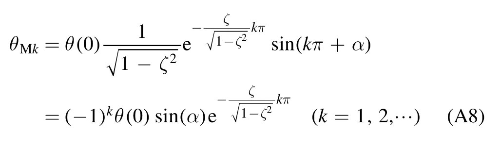
The absolute value of the extreme value of the torsion angle is

Then
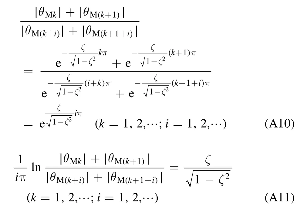
So,the calculation formula of the damping ratio is

A1.2.Free vibration under instantaneous impulse
The free vibration equation of a torsional pendulum in static state under instantaneous impulse is

The corresponding time of extreme points is

The calculation formula of the vibration period is

The torsion angle corresponding to the extreme point is

At the same time,the formula can also be obtained:

Comparing formulas (A6),(A7),(A11) with formulas(A17),(A18),(A22),it can be seen that although the initial conditions of free vibration are different and the free vibration equations are different,the calculation method of the system parameters is consistent when the parameters of the torsional pendulum system are calibrated,and formula (A4) can be used to calculate the damping ratio.
A2.Calibration results
The angular displacement variation curve of the free swing of the beam is collected by the displacement sensor,as shown in figure A1.
A2.1.Calibration of natural frequency
The relationship between the damping vibration frequency ωdand undamped natural frequency ωnis


Table A1.The result of free oscillation period.

Table A2.The damping ratio ζ.
The vibration with damping is directly measured.By analyzing the curve data,the result of the free oscillation period can be obtained as shown in table A1.
The average value of damped vibration frequency is 3.98244 rad s?1,the standard deviation is 0.012494 rad s?1,and the relative error is 0.3137%.
A2.2.Calibration of damping ratio
The damping ratio of the system in an atmospheric environment is calculated according to formula (A12).According to the inflection point coordinates of the measured data curve,the damping ratio ζ can be obtained as shown in table A2.

Table A3.Quality of the reference beam.
The average damping ratio is 5.5596 × 10?4,the standard deviation is 0.5672 × 10?4,and the relative error is 10.2%.
According to the damping ratio ζ and the damped vibration frequency ωd,the undamped vibration frequency ωncan be calculated as 3.982441 rad s?1.
A2.3.Rotational inertia of reference beams
The size of the reference beam is shown in figure A2.Installation diagram of reference beam on torsion pendulum is shown in figure A3.
By inserting the size value,the volume of the reference beam is 23.8514 cm3.
The quality of the reference beam is measured by highprecision balance(METTLER XS105,precision 0.1 mg).The results are as shown in table A3.
The average mass of the reference beam is 67.51199 g,the standard deviation is 0.0002522 g,and the relative error is 0.00037%.
Based on the measured values of mass and volume,the reference beam density was calculated as ρ = 2.8305 g cm?3.
The moment of inertia is calculated below.Among them,the rectangular,cylindrical and conical moment of inertia formula are as follows:

According to the cuboid formula,the moment of inertia J0of the reference beam is 1.8374 × 10?4kg·m2.
A2.4.Calibration of rotational inertia
First,the frequency of the reference beam installed on the torsion pendulum should be measured.The angular displacement variation curve with reference beam swing is collected by the displacement sensor,as shown in figure A4.
By analyzing the curve data,when the reference beam is installed,the swing period of the torsional pendulum is as shown in table A4.
The average ω′dwith the reference beam is 3.442242 rad s?1,the standard deviation is 0.01145 rad s?1,and the relative error is 0.3326%.
According to the damping ratio ζ and the damped vibration frequency ω′d,the undamped vibration frequency ω′ncan be calculated as 3.442243 rad s?1.
The moment of inertia is


Table A4.Swing period of the torsional pendulum.
The relationship among the frequency of undamped vibration,the inertia and the torsion stiffness coefficient is

So,k is 0.0086 N·m rad?1.
A2.5.Impulse formula
According to the measurement model of the impulse torsion pendulum,the relationship between the impulse I and the maximum angle θmaxis

The torsion pendulum parameters J,ωnand ζ are obtained by the above calibration.d is the distance between the torsion pendulum force point and the torsion pendulum shaft,namely the length of the force arm,and d can be measured directly.Because the beam swing caused by microimpulse satisfies the small angle assumption,we have

where L is the swing distance of the beam measured by the displacement sensor,and d′ is the moment arm value of the measuring point of the displacement sensor,which can be measured directly.Therefore,the relationship between the impulse I and the measured value L of the displacement sensor is

According to the calibration,the system parameters are:moment of inertia J = 5.4282 × 10?4kg·m2;the natural vibration frequency ωn= 3.9824 rad s?1;damping ratio ζ = 5.56 × 10?4;ablation arm d = 91.048 mm;measurement arm d′ = 144.524 mm.So

猜你喜歡
劇作家(2023年3期)2023-06-12 13:11:51
化工管理(2021年7期)2021-05-13 00:45:40
現(xiàn)代塑料(2021年2期)2021-04-03 16:49:25
幽默大師(2020年11期)2020-12-08 12:01:58
紅樓夢學刊(2020年5期)2020-02-06 06:20:44
幽默大師(2019年11期)2019-11-23 08:47:48
幽默大師(2019年11期)2019-01-14 17:47:37
上海建材(2018年3期)2018-08-31 02:27:54
百家講壇(紅版)(2017年3期)2017-09-08 06:33:02
中國商論(2016年34期)2017-01-15 14:24:21
 Plasma Science and Technology2022年10期
- Plasma Science and Technology的其它文章
- Study of a 105 GHz short-pulse dummy load for the electron cyclotron resonance heating system with the quasi-optical method
- Cleaning of nitrogen-containing carbon contamination by atmospheric pressure plasma jet
- The effects of dilution gas on nanoparticle growth in atmospheric-pressure acetylene microdischarges
- The effect of nitrogen concentration on the properties of N-DLC prepared by helicon wave plasma chemical vapor deposition
- Development of low power non-thermal plasma jet and optimization of operational parameters for treating dyes and emerging contaminants
- A comparison of power measurement techniques and electrical characterization of an atmospheric pressure plasma jet