
A 3 Giga Sample Per Second 14-bit Digital Receiver with 9GHz Input Bandwidth for Solar Radio Observation
2022-09-02 12:25:16YuanyuanZhang張園園LeiZhang張磊ZiqianShang尚自乾GuangLu路光ZhaoWu武昭YanruiSu蘇艷蕊YaoChen陳耀andFabaoYan嚴(yán)發(fā)寶
關(guān)鍵詞:張磊
Yuanyuan Zhang (張園園)Lei Zhang (張磊)Ziqian Shang (尚自乾)Guang Lu (路光)Zhao Wu (武昭)Yanrui Su (蘇艷蕊)Yao Chen (陳耀)and Fabao Yan (嚴(yán)發(fā)寶)
1Laboratory for ElectromAgnetic Detection (LEAD),Institute of Space Sciences,Shandong University,Weihai 264209,China; yanfabao2022@163.com
2 School of Mechanical,Electrical &Information Engineering,Shandong University,Weihai 264209,China
Abstract A new digital receiver with excellent performances has been designed and developed for solar radio observation,which can receive the radio signal from direct current (DC)to 9 GHz in the direct acquisition way.On the digital receiver,the analog-to-digital converter (ADC) with 14-bit,two input channels and 3 Giga Samples per second(Gsps) are used to acquire observed signal,and the field-programmable-gate-array chip XCKU115 acts as the processing module.The new digital receiver can be used to directly sample the solar radio signals of frequency under 9 GHz.When receiving the solar radio signal above 9 GHz,the new digital receiver can save 1–2 stages of frequency down-conversion,and effectively improve many indexes of the solar radio observation system,i.e.,the time resolution,analog front-end circuit,weight and volume of the analog circuit system.Compared with the digital receiver with sampling rate below 1 Gsps used in existing solar radio telescope,the new digital receiver reduces the frequency switching times of large bandwidth,which is beneficial to improving the frequency and time resolutions.The ADC sampling resolution of 14 bits,providing a large dynamic range,is very beneficial to observing smaller solar eruptions.This receiver,which would be used in the solar radio observation system,well meets the latest requirements with the resolutions of time(≤1 ms)and frequency(≤0.5 MHz)for fine observation of radio signals.
Key words: instrumentation: spectrographs–techniques: spectroscopic–techniques: radar astronomy
1.Introduction
Solar eruptions have an important impact on space weather(Chen et al.2016;Liu et al.2018;Song et al.2021).Solar eruptions produce radio signals from the meter band to the millimeter band,and the radiation intensity could be increased to thousands to tens of thousands of times,instantaneously(Oh et al.2011;Du et al.2017;Yan et al.2020).These eruptions may result in the interruption of short-wave radio communication (Ichimoto et al.1985;Chen et al.2017).Researching and analyzing the solar eruptions are thus important to human society.
A solar radio telescope,generally composed of antenna,analog front-end circuit,digital receiver and so on,is an important instrument to observe solar eruptions(Fu et al.2004;Geng et al.2018;Shang et al.2022).The digital receiver,as one of the most important parts of solar radio telescopes,could effectively improve many indexes of the solar radio observation system,i.e.,the time resolution,analog front-end circuit,weight and volume of the analog circuit system.Developing a new high-performance digital receiver is very necessary in the requirement of new observation needs.
In the solar radio telescope that operating currently,due to the low sampling rate and low sampling accuracy of the digital receiver,down conversion and tens to hundreds of local oscillators are needed in analog front-end circuit to observe broadband signals.For example,China?s MUSER-II which receives radio signals of 2–15 GHz has 3-level down conversion processing (Geng et al.2016).Converting signals of 2–15 GHz to the intermediate frequency of 250 MHz with 400 MHz bandwidth uses more than ten Local oscillator signals in the analog front-end.The first stage down conversion adopts frequency agile devices to convert 2–15 GHz signals to 3.5 GHz and 7.5 GHz intermediate frequency signals,respectively,with the bandwidth of 400 MHz.The first agile local oscillators need to output more than ten single frequency signals.The second stage down conversion needs two local oscillators with the frequency of 4.7 GHz and 8.7 GHz respectively.The signals are converted to intermediate frequency of 1.2 GHz with 400 MHz bandwidth.The third down conversion requires one local oscillator of 1.45 GHz,which converts the signals to intermediate frequency of 250 MHz with bandwidth of 400 MHz.The solar radio telescope located in Owens Valley also uses a similar processing method with MUSER-II (Dou et al.2009).The system has four channels for analog-to-digital converter (ADC) acquisition,and each channel has an input instantaneous bandwidth of 500 MHz.The standard time resolution is 100 ms,and the sampling rate of digital receiver is 1 Giga sample per second (Gsps) with the resolution of 8 bits.Multistage down conversions are used in the system.However,we should note that multistage down conversions also bring more signal interferences to the receiving systems and reduce the performance index of the solar radio observation system,i.e.,the time resolution,weight and volume of the analog circuit system(Yan et al.2009;Liu et al.2019).
In some digital receivers with high-speed sampling,the sampling rate is as high as 10 Gsps,but the sampling accuracy is low that the resolution of the ADC sampling rate is only 4 bits.So,it cannot satisfy the precise observation of solar radio bursts (Jiang et al.2016).
Radio signals from the Sun may be generated in a wide frequency band,and the radiation intensity could be increased to thousands to tens of thousands of times,instantaneously(Oh et al.2011;Du et al.2017;Yan et al.2020).When the Sun bursts,some bursts may last only milliseconds,and some bursts will produce radio signals in a wide frequency band(Tan et al.2018).Therefore,a new radio observation equipment should have high resolution and large dynamic range to obtain more comprehensive information about solar eruptions,including strong eruptions and weak eruptions.Developing a high sampling rate digital receiver with a high sampling accuracy is therefore urgent in future radio observations,to effectively improve many indexes of the solar radio observation system,i.e.,the time resolution,frequency resolution,and dynamic range.
We have developed a new digital receiver with high dynamic range,high resolution in time and frequency of solar radio telescopes.The new receiver has two channels for sampling,and the sampling rate of each channel is 3 Gsps with sampling accuracy of 14 bits.The input analog signal could be in the range from direct current (DC) to 9 GHz.When the digital receiver is applied to the 1–9 GHz solar radio observation system,the matching structure of analog front-end will be greatly simplified,i.e.,the multiple down-conversions are not needed.When the digital receiver is applied to the solar radio observation system above 9 GHz,the 1–2 mixing processing can be reduced.The high sampling rate (3 Gsps) could reduce the frequency switching times with a large bandwidth,and improve the frequency and time resolution of observation.Other indexes of the solar radio observation system can also be improved,i.e.,signal interferences caused by multiple mixing are avoided,and the cost,size,weight and power consumption of the analog front-end are reduced.The sampling accuracy of 14 bits that improves the dynamic range of the observation system is very beneficial to the observation of smaller solar eruptions.The research background is introduced in Section1,and then the instrument requirements for observation are analyzed in Section2.The specific contents of the digital receiver are introduced in Section3.In Section4,the analog front-end scheme using digital receiver is introduced.The test results are introduced in Section5.Section6is the conclusion of the article.
2.Requirement Analysis of Radio Observation for the New Generation Digital Receiver
With the demands of scientific research,the requirements of solar radio telescopes on high frequency resolution,time resolution and other indicators are proposed.Therefore,it is of great significance to develop solar radio telescopes with wider spectrum and higher sampling rate.In this section,we analyze the observation indexes to meet high observation requirements.
2.1.Spectrum Observation Requirements
For solar radio astronomy research,higher sensitivity and higher time-frequency resolution help observe smaller bursts and finer structures.However,the design of higher index for the telescope always faces many contradictions.For example,in a certain observation range,when the frequency resolution increases,the time resolution will decrease;when the time resolution increases,the frequency resolution will decrease.
Long-term observational studies have found that solar bursts can often be divided into many small bursts ranging from long to short time,among which spike bursts are the smallest bursts(Tan et al.2018).Compared with other bursts,the small bursts such as radio spike bursts,radio point bursts and narrow-band bursts have the same characters that the average lifetime is the shortest and the average bandwidth is the narrowest.They can be regarded as the structural unit that constitutes other bursts.When the frequency of the bursts becomes high,the average life span would become shorter(Tan et al.2018).According to the calculation,the average life span is about 25 ms at 1 GHz and the average life span is about 2.5 ms at 15 GHz.At the same time,the average bandwidth of these small bursts increases with frequency.The relative bandwidth of most small bursts is between 0.5% and 3% (Tan et al.2018).According to 0.5% calculation,the minimum burst bandwidth at 500 MHz is 2.5 MHz.
From the points of view of recognition,each peak eruption requires at least two observation points,so the time resolution is less than half of the average lifespan.At the same time,the frequency resolution should be less than half of the average bandwidth.Therefore,the development of a wide-band solar radio observation system under 15 GHz with a frequency resolution(≤0.5 MHz)and a time resolution(≤1 ms)can well meet the requirements of the observation of those tiny bursts.
In the broadband (≥9 GHz) single-system solar radio observation system,there is no observation system with both high time resolution (≤1 ms) and high frequency resolution(≤0.5 MHz)in the world.The ability to accurately detect small bursts has become the necessary for a new solar radio telescope.
The solar radio observation system using this new digital receiver would well meet the above requirements for the resolution of time and frequency.
2.2.Spectral Radioheligraph Requirements
On the other hand,synthetic aperture interferometry is the most commonly used technique for spectral radioheligraph of the Sun.In the process of spectral radioheligraph of the Sun,pairwise digital correlation calculation of each antenna signal is the key technology of coherent observation of solar radio signal(Liu et al.2019).When the solar radio signal is received by two antennas,they are amplified and filtered.Then the data is transferred to the digital receiver for coherent processing.The digital correlator measures this correlation and obtains the socalled “visibility function” (Liu et al.2019).Our new generation digital receiver has two analog input channels,which is also very suitable for synchronous correlation operation.The two acquisition channels use the same working clock,and the sampled data are transmitted to field-programmable-gate-array (FPGA) through JESD204B interface for further digital correlation processing.Because the two acquisition channels are driven by one clock,the accuracy of synchronization is high that is much less than one sampling period(~0.3 ns).At the same time,the ADC used in the digital receiver has the function of multi device synchronization.When the digital receiver is set to the synchronous acquisition mode,multiple digital receivers can synchronize the clock and still have synchronization accuracy.Because the digital receiver adopts optical fiber transmission,it can transmit in the range of tens of kilometers,which is especially conducive to the synchronous data acquisition of heliograph antenna array with baseline length of tens of kilometers.
3.The New Generation Digital Receiver
3.1.Hardware Design for the Digital Receiver System
The hardware architecture design scheme of the digital receiver is shown in Figure1.The hardware architecture is divided into two parts: ADC sub board on the left and FPGA carrier board on the right.The two boards are connected together through FPGA Mezzanine Card (FMC) interface.In the ADC FMC sub board,ADC9208 performs the function of acquiring data,and HMC7044 chip provides the working clock.There are FPGA chip XCKU115,power supply module,memory module and various peripherals on FPGA board.XCKU115 chip is directly connected with ADC chip through FMC interface.In the system,XCKU115 chip completes the functions of data receiving,parsing,processing and cache controlling.
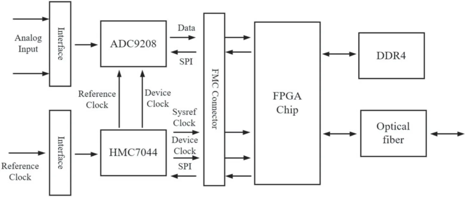
Figure 1.Hardware architecture of the digital receiver.
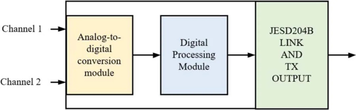
Figure 2.Internal structure and function diagram of ADC9208.
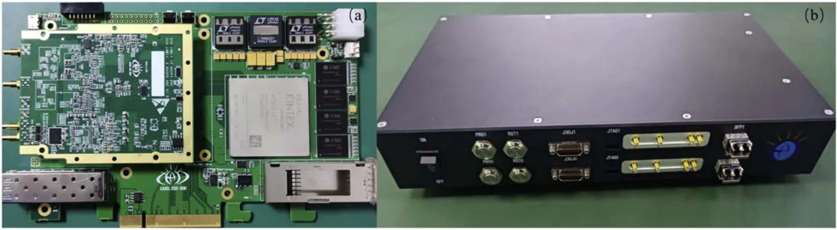
Figure 3.(a) Connection diagram between the ADC card and FPGA board,(b) physical picture of the digital receiver.
Under the same sampling accuracy,when the sampling rate of ADC is too high,its effective bits will decrease.As shown in Table1,compared with the ADCs on the market,the effective bits of ADCs with sampling rate above 1 Gsps are always more than 9 bits when the sampling accuracy is 14 bits.But when the tested input signal is close to the maximum value of the analog input signal,their effective bits will be reduced,generally between 8 and 9 bits.Considering the analog input bandwidth,sampling rate and sampling accuracy of each ADC,AD9208 is best choice as the analog to digital converter.
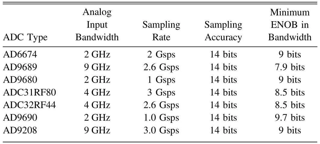
Table 1Performance Comparison of Various Advanced ADCs
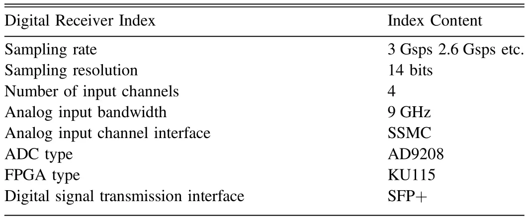
Table 2The Indexes and Performances of the New Digital Receiver
ADC9208 is a dual channel,14-bit,analog-to-digital converter,with on-chip buffer,sample and hold circuit.Its sampling rate can be flexibly set between 2.5 and 3.1 Gsps.The total power of each channel is about 1.65 W when working at 3 Gsps.As shown in Figure2,the programmable filters and digital down converters (DDC) modules are integrated behind the ADC core,which have the function of filtering,extracting and compensating.AD9208 is also integrated with JESD204B data transmission interface.The JESD204B interface is used to frame and encapsulate the sampled data and transmit them in the form of data packets.The transmission channel that can be used is up to eight lanes at the same time,and the line rate supported by each transmission channel is up to 16 Gigabits per second(Gbps).The bandwidth of analog input is 9 GHz,which can provide wide input bandwidth,fast sampling rate and excellent linearity.
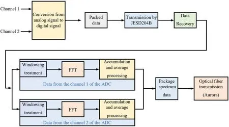
Figure 4.The flow chart of signal processing performed by the new digital receiver.
XCKU115 chip is selected as the master chip with excellent performance and powerful resources of logical units,digital signal process(DSP)slices and transceivers.Based on the rich logic,DSP resources and high-speed interface,it is an excellent platform to implement the function of real-time signal processing and transmission of solar radio telescopes (Yan et al.2017,2021).
This information has been described earlier that the data sampled by ADC9208 is transmitted to FPGA through JESD204B interface.The transmitter of JESD204B is located in ADC chip,and the receiver is located in FPGA chip.Both terminals need to be provided with high-precision clocks.HMC7044 chip is a high-performance Jitter Attenuator with two cascaded PLLs,which can be flexibly configured through SPI interface.The output tunable range is as high as 3.2 GHz.HMC7044 provides 14 low noise and configurable outputs that can be flexibly connected to many different devices,including various converters,FPGA and mixer.HMC7044 also has the function for various clock management and distribution,therefore,a developer can build a completed system for clocks using a single device.
Based on the above technologies and methods,the digital receiver has already developed successfully.Figure3(a) is the physics image of ADC card which has two channels for analog input.The ADC card is mainly composed of an ADC chip and a clock chip.The FMC interface on the ADC card is used to directly connect with the FPGA processing card.The module indicated by the red arrow in Figure3(a)is the FMC interface.There is also a corresponding FMC interface on the FPGA board.Between ADC card and FPGA board,the ADC card is directly buckled to FPGA board through the FMC interface.Figure3(b) is the picture of the digital receiver of four analog input channels.It consists of a power management module and two high-speed acquisition systems as shown in Figure2.So,the digital receiver has four analog channels for input.The two acquisition systems can be configured as a synchronous mode with the same sampling rate,and they can also be configured as different sampling rates.This design has great flexibility and is very conductive to ultrawideband (UWB) observation of solar radio.
As shown in Table2,we have summarized the indexes and performances of the new digital receiver.In the table,the sampling rate,sampling resolution and other important parameters of the new digital receiver are listed in detail.
As mentioned above,the new digital receiver consists of two independent acquisition systems,and each with two analog sampling channels.The hardware architecture of the two acquisition systems is the same,and their signal processing flow is also the same.As shown in Figure4,it is the signal processing flow chart of one acquisition system in the digital receiver.In an acquisition system,the two sampling channels of the ADC are driven by a sampling clock,so the signals of the two analog input channels are sampled at the same time.Then,the data of the two sampling channels are packaged and transmitted to FPGA board through JESD204B interface.In FPGA,the received data is restored to the original data from two channels.Then,the data of each channel are calculated separately,including windowing processing,FFT operation and accumulation processing.Windowing the data is helpful to reduce spectrum leakage.The FFT operation can transform the data from time domain to frequency domain.Accumulating and averaging the spectrum data is conductive to improving the signal-to-noise ratio (S/N) of the signal.After the two-way data operation is completed,the data are packaged together and then transmitted to the remote computer through the optical fiber transmission cable.The optical fiber transmission adopts Aurora protocol,which can support the transmission rate of 10 Gsps.
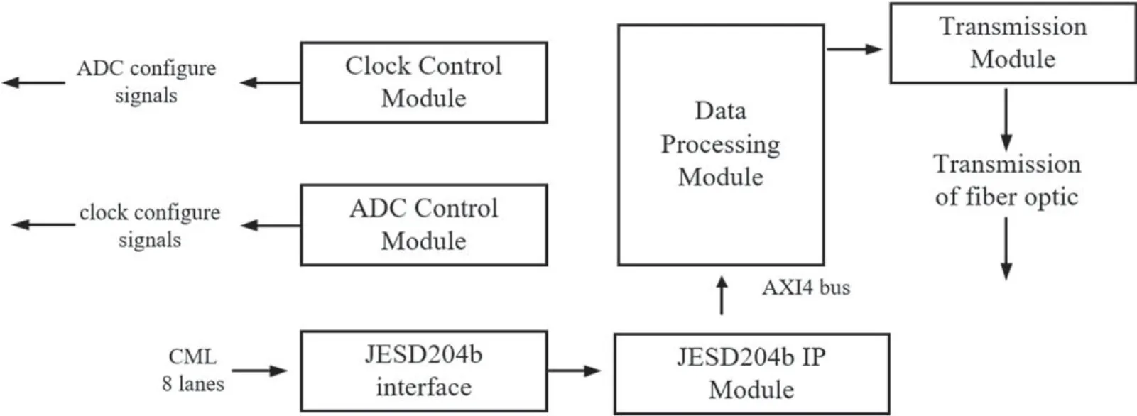
Figure 5.Block diagram of the software.
3.2.Software Design for the Digital Receiver System
The hardware system of the digital receiver which integrates with a variety of advanced technologies is very complex and could realize many functions.So,in order to control the system,it is necessary to have clear module hierarchy and good code style.The soft code module is divided into several module which will be conductive to debugging,management and function upgrade.
By Vivado17.4 software,we have developed code that can make this hardware platform work well.This soft code module has several parts,which are clock configuration module,AD configuration module,JESD204B IP configuration module,data processing module and transmission module.The detail software design framework is shown in Figure5.It can be seen that each module is independent and there are some connections with each other.The functions of each module are described in detail below.
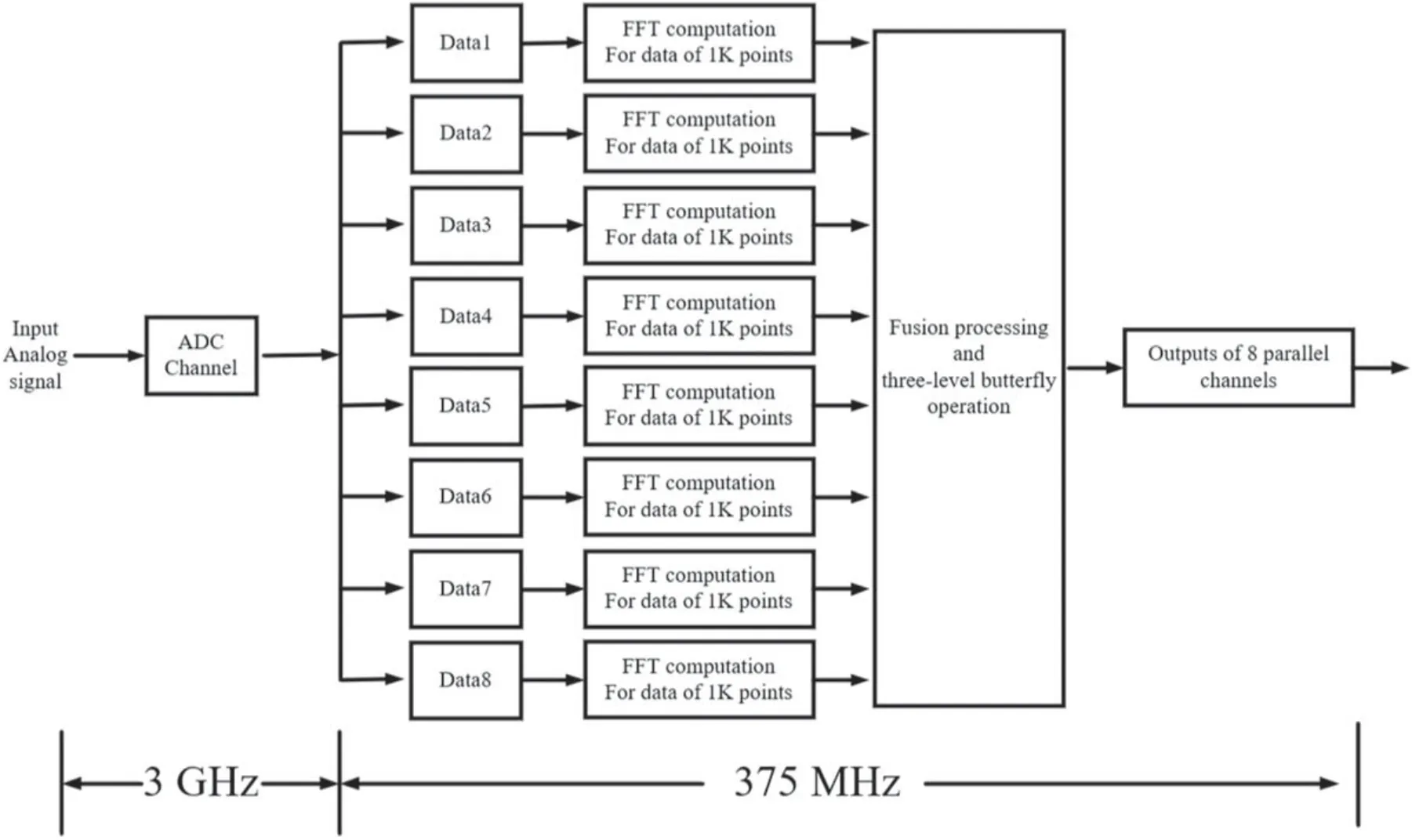
Figure 6.Function diagram of internal data processing.
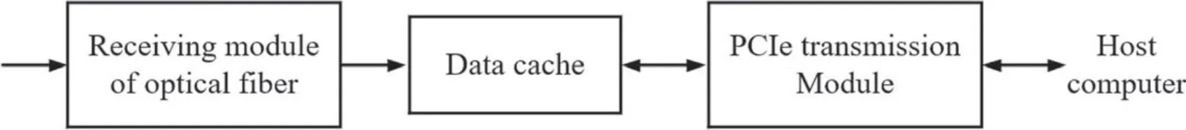
Figure 7.Block diagram of transmission part.
3.2.1.Clock Configuration Module
The clock configuration module is mainly used to generate accurate clock for the system of JESD204B in the digital receiver.JESD204B is the communication interface between the ADC and FPGA module.
For JESD204B data transmission,the most important problem is the synchronization between the transmitter and receiver of JESD204B in which all device clocks and reference clocks should be homologous and accords with the specific phase relationship.In practice,we can adjust the delay of each channel reasonably to ensure the proper phase relationship between the clocks for the device and reference.
In the JESD204B system,an SYSREF signal is used to generate local multi-frame clock (LMFC) of each channel for alignment.The device clock is used to sample the rising edge of SYSREF signal to determine the alignment time of LMFC.
3.2.2.ADC9208 Configuration Module
ADC9208 configuration module is used to make the ADC work properly.ADC9208 has two working modes: full bandwidth mode and DDC mode.In the full bandwidth mode,the decimation filter inside the chip is ignored,and the direct acquisition for radio frequency (RF) can be carried out.In the DDC mode,the on-chip DDC function is enabled,the on-chip numerically controlled oscillator (NCO) frequency and decimation filter coefficient are set,and the pre-selected frequency band can be received.Therefore,we can make reasonable choices according to the actual requirements.In this system,ADC is configured in the full bandwidth mode.
To make it work correctly,it needs to configure hundreds of registers.It is also sensitive to the configure order of registers.So,at this project,a set of strict configuration procedures and methods for ADC9208 is established.The configuration program mainly follows the following steps: (i) power on ADC and CLK chip,and issue SPI Soft Reset to ADC.(ii)Power down the ADC link using SPI.(iii) Keep ADC in power-down mode using SPI.(iv)Configure ADC.In this step,it is necessary to configure the parameters required for ADC operation,including operation mode selection,analog input control,buffer current control,parameter configuration of JESD204B transmitter and so on.(v) Power ON ADC using SPI.(vi)Issue a Data Path Soft reset.(vii)Power UP the ADC link.(viii) Initialize the JESD204B link and issue the link stability.Under the condition of that the input clock is stable,once the ADC starts to work normally,the sampled data can be output continuously.
3.2.3.Data Transmission Module between ADC and FPGA
Data transmission between ADC and FPGA is realized by JESD204B interface.In ADC,the transmitter groups and packs the sampled data and then transmits it through eight high-speed serial transceivers.The receiver of JESD204B protocol is implemented on the FPGA.FPGA receives and analyzes the data from the high-speed serial transceiver in real time.In the project of our digital receiver,the highest transmission rate between ADC and FPGA is up to 120 Gbps.
3.2.4.Data Processing Module
The astronomical signal processing module of FPGA operation board is the function of spectrum analyzer.The core work of spectrum analyzer is to transform digital signal from time domain to frequency domain by FFT.
In this project,the number of converts is set as 2 and the number of lanes is set as 8 in full bandwidth mode,and the data of eight sampling points are transmitted in each clock cycle.According to the actual needs,we have established a parallel real-time calculation method of 8192 points as shown in Figure6.The data sampled by one channel ADC is parallelized and transmitted to FPGA.The clock frequency of ADC for sampling is 3 GHz.When it is divided into eight links of parallel transmission,its working frequency is 375 MHz,and the working clock of FFT operation is also 375 MHz.As shown in Figure6,when the data is divided into eight links and transmitted to FPGA in parallel,performing the FFT operation of 1K points for each link.Then,the 8-link data are fused and performed by butterfly operation,and the obtained spectrum data is equivalent to the data obtained by 8K FFT operation directly (Luo et al.2017;Yu et al.2020).
3.2.5.Transmission Module
The function of transmission module is used to transmit the processed data to the host computer through Ethernet for further display and storage.In this project,the amount of data to be transmitted is enormous.In order to reduce the pressure of data transmission and noise interference,the power values of corresponding frequency point are accumulated for many times before data transmission.Compared with electrical transmission,optical fiber transmission has the characteristics of good confidentiality,light weight and wide transmission frequency.
As shown in Figure7,the spectrum data of the digital receiver is sent to the receiving board through the optical fiber,and then the data is received the receiving module of the receiving board.After further processing,the data is buffered on the receiving board.Finally,the data is uploaded to the host computer through the PCIe interface.
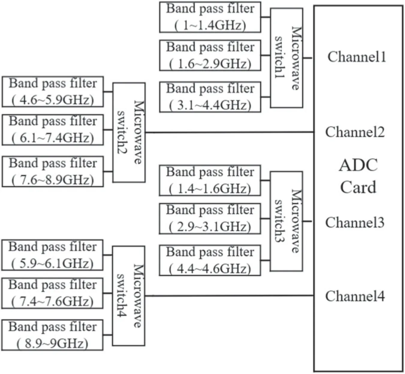
Figure 8.The acquisition scheme for the ultra-wideband radio signal.
4.Scheme of Digital Receiver Applied to Solar Radio Observation
Due to the large frequency span,it is difficult for a single paraboloid antenna to maintain high signal acceptance and flatness in the range of DC-9 GHz.Therefore,we present a scheme for the frequency band division for a single antenna system with the working frequency band of 1–9 GHz.The frequency band division scheme and parameter calculation of the observation system with frequency band more than 9 GHz are also similar to this system.
As an important performance index,the analog input bandwidth of ADC9208 is 9 GHz which means that the receiver we designed can sample the signal within 9 GHz directly without multiage processing of down conversion.Here,we give a channel division scheme for 1–9 GHz analog receiver based on the digital back-end.According to the law of Nyquist sampling,the instantaneous bandwidth of the input signal should not exceed the value of half of the sampling rate,namely,the maximum instantaneous input bandwidth is 1.5 GHz.At the same time,according to the bandpass sampling theorem,ADC can sample the signal whose frequency exceeds its sampling rate.When the frequency of input signal exceeds the ADC sampling rate,the bandwidth of the input signal should be less than half of the sampling rate in order to avoid signal aliasing.
Although the maximum input bandwidth is 1.5 GHz,the filter has a weaker ability to suppress signals in the sidebands.So,it is easy to cause signal aliasing.Therefore,we designed a more reasonable division plan of sub-band according the second Nyquist sampling theorems (Liu et al.2001;Hennenfent &Herrmann2008).As shown in Figure8,a four-channel digital receiver is developed for the full coverage acquisition of 1–9 GHz solar radio signals.The sampling rate of ADC1 is configured as 3 Gsps.The sub-bands of the signal sampled by channel1 are 1–1.4,1.6–2.9,3.1–4.4 GHz,and those of channel2 are 4.6–5.9,6.1–7.4,7.6–8.9 GHz.In order to not lose bandwidth,the sampling rates of channel3 and channel4 are configured as 2.6 Gsps to sample the rest of the spectrum.The frequency band of the signal sampled by channel3 is 1.4–1.6,2.9–3.1,4.4–4.6 GHz.The frequency band of signal sampled by channel4 is 5.9–6.1,7.4–7.6,8.9–9 GHz.
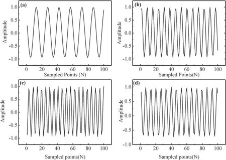
Figure 9.(a) ADC acquisition waveform of 200 MHz input signal,(b) ADC acquisition waveform of 400 MHz input signal,(c) ADC acquisition waveform of 2.4 GHz input signal,and (d) ADC acquisition waveform of 8.4 GHz input signal.
The full coverage acquisition of 1–9 GHz signal can be realized by controlling the microwave switch by FPGA.The acquisition time of each channel can be set to the level of microseconds,and the full coverage of 1–9 GHz signal can be realized through cycle switching.
According to the calculation,the frequency resolution is 366 kHz when performing the FFT operation of 8K data of the digital receiver.Performing a single 8K FFT operation,341.3ns would be consumed.Then a necessary integration operation is performed,and the time for integration is set to 0.2 ms.The sample of full frequency band can be realized by three channels switching.The overall time resolution is about 0.6 ms,which meets the time resolution index of less than 1 ms.
5.Experimental Data
Figures9(a),(b),(c)and(d)are ADC acquisition waveforms with the input signals of 200 MHz,400 MHz,2.4 GHz and 8.4 GHz.Abscissa is the order of sampling points,and ordinate is the amplitude of sampling signal after normalization.Figure9shows that the receiving system can not only receive signals below the sampling frequency,but also sampled the signals above the sampling frequency.The frequency of the input waveform can be calculated accurately when using FFT to process the data sampled above.
The good linearity of the receiver system is an important guarantee for the accuracy of solar radio observation.In order to obtain the characteristic of the linearity index of the receiver system,the receiver system has received several tests for linearity,and the corresponding result are shown in Figure10.The full scale of the test is set at 1.7 V,and the range of input power varies from?60 dBm to 5 dBm with the input frequency of 2.4 GHz.Figure10is a fitting formula obtained from the test data of ADC linearity.First,divide each data of the power values sampled by the digital receiver by the minimum value to obtain the ratio between each data and the minimum value,and then normalize the ratio.The ordinate of Figure10is the normalized value.The results show that the Pearson correlation coefficientris 0.99999,which indicates that the receiver system has excellent linearity and the range of linearity is more than 65 dB.
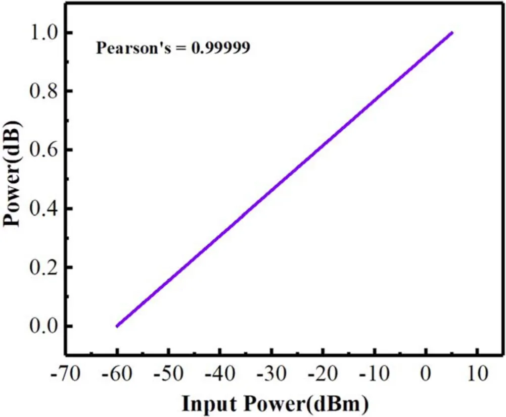
Figure 10.Linear fitting after normalization.
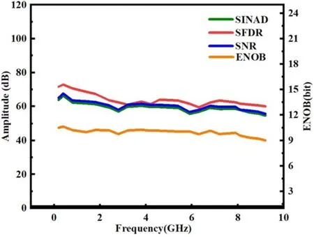
Figure 11.Test results of the digital receiver.The green,red and blue lines display the SINAD,SFDR and S/N values,respectively.The yellow line displays the ENOB value
At the same time,a series of performance tests on the receiver’s ADC are carried out with the input signal generated by N5183B.During the test,the signals of multiple frequency points are input into the ADC,and the ADC samples the signals directly.The FFT is performed every 8K points for the sampled data of ADC.The test frequency covers from DC to 9.2 GHz.Figure11is the test result of the characteristics of the digital receiver (Yan et al.2021).The S/N and spurious-free dynamic range (SFDR) are the parameters indicating signal quality.The effective number of bits (ENOB) indicates the actual resolution of the receiving system.Signal to noise and distortion ratio (SINAD) is also the parameters revealing the influence of signal noise and harmonics.
The higher S/N value indicates that the noise interference of the signals is smaller.The test results show that in the frequency range of DC-9 GHz,the S/N value is about 60 dB.In the frequency range of DC-9 GHz,the S/N value is no obvious fluctuation.
SINAD can well reflect the overall dynamic performance of ADC.The test results show that the values of SINAD are about 60 dB in the range of DC-9 GHz.The measured SINAD values show that the digital receiver has good characteristics and can meet the requirements of high-quality solar radio observation.
The calculation of ENOB is obtained by SINAD,which is used to measure the conversion quality of data converter relative to input signal in Nyquist bandwidth.Compared with S/N,ENOB can indicate signal integrity better because it takes system error into account.The test results show that the ENOB are larger than 9 in the range of DC-9 GHz which indicates that the ADC has good signal integrity.
SFDR,which means no spurious dynamic range,is an important performance index of ADC.As shown in Figure11,SFDR is 60–75 dB in the range of DC-9 GHz,which indicates that the receiving system is in good condition.When the Sun bursts,its radiation flux will increase by 10–40 dB,so the high SFDR of the receiver system can well meet the needs of solar radio observation.
According to the above test results,it shows that the receiving system has good performance.The excellent S/N and SINAD provide the ability to observe weak solar radio signals.The high SFDR ensures that the receiving system can not only accurately observe the radiation flow of the quiet Sun,but also observe the radiation flow during solar burst.The good linearity ensures that the receiving system can accurately record the accurate variation of solar radiation flux.
In order to further verify the usability of the digital receiver,a simple observation experiment has been done.The test platform consists of a 2.4 m antenna,an amplifier,a filter,a new digital receiver and a computer.The working frequency band of the filter is 6.1–7.4 GHz.In the experiment,we tested the signal reception of the antenna in different directions.
The test block diagram we built is shown in Figure12.The tracking antenna has an aperture of 2.4 m and can receive solar radio signals with a frequency range of 1–10 GHz.Due to the weak solar radio signal in the quiet state,the low noise amplifier(LNA)is used to amplify the received signal.A filter with an operating frequency band of 6.1–7.4 GHz is used to filter signals outside the frequency band.The filtered signal is transmitted to the new digital receiver for sampling and processing.The microwave transmission cables are used for analog signal transmission between antenna,amplifier,filter and digital receiver.The digital receiver and the host computer are connected through optical fiber transmission cables.During the measurement,the accumulation time was set to 0.2 ms and the frequency resolution was set to 366 kHz.We carried out several groups of observation experiments,and each lasting about 2 minutes.
Figure13shows the relationship between the spectrum and time.In Figure13,the ordinate represents frequency and the abscissa represents time.From the beginning,the antenna points to the sky,which is the signal obtained by the receiving system.The signal comes from the sky background and it is weak.And then,the antenna?s direction changes and gradually points to the Sun.So the signal gradually increases and remains stable.Apparently,the value when the antenna pointing to the Sun is about 1–2 dB higher than the value when the antenna pointing to the sky in the frequency of 6.1–7.4 GHz.It also indicates that the digital receiver can obviously observe the signal of the solar radio in a quiet state in the experiment.So,the digital receiver can be well used for solar radio telescope in the corresponding frequency band.
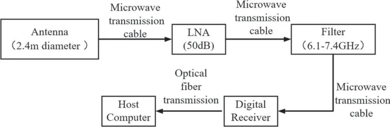
Figure 12.Flow chart of solar radio spectrum observation with the new receiver.
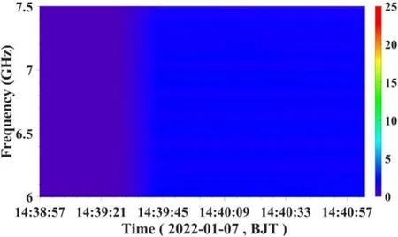
Figure 13.The test result of the spectrogram when the antenna is in different directions.
6.Conclusion
The measurement shows that the new generation of digital receiver has good performance.The new digital receiver can be used for direct acquisition for the solar radio signals of frequency under 9 GHz.When receiving the solar radio signal above 9 GHz,using the new digital receiver can save 1–2 stages of frequency down-conversion,and effectively improve many indexes of the solar radio observation system.So,the structure of the circuit system for analog front-end can be simplified by using the new digital receiver.At the same time,the weight and volume of the analog circuit system can be reduced.The method effectively avoids the signal interference caused by multiple down-conversion processing.Compared with the digital receiver with sampling rate below 1 Gsps,the sampling rate up to 3 Gsps is very beneficial to reduce the frequency switching times of large bandwidth,which is beneficial to improve the frequency and time resolution of observation data.The sampling rate of 14 bits that improves the dynamic range of the observation system is very beneficial to the observation of smaller solar eruptions.
The solar radio observation system using this new digital receiver would well meet the latest requirements with the resolution of time (≤1 ms) and frequency (≤0.5 MHz) for fine observation of radio signals.Based on the good advantages of the new digital receiver,it will be soon applied in the solar telescope of the observation station in Chashan.
Acknowledgments
This research was supported by the National Natural Science Foundation of China (grant Nos.42127804,41774180 and 41904158),Shandong postdoctoral innovation project(202002004) and Young Scholars Program of Shandong University,Weihai (208220201005).We thank the engineers’assistance of the company of Beijing Kunchi Technology during the digital receiver development.We also thank Liu Jie for providing the test instruments.
猜你喜歡
Chinese Physics B(2024年2期)2024-02-29 09:19:22
中國民間療法(2021年19期)2021-11-20 06:22:32
Chinese Physics B(2021年6期)2021-06-26 03:04:32
北極光(2020年1期)2020-07-24 09:04:06
Acta Mathematica Scientia(English Series)(2018年2期)2018-05-05 07:09:39
北方文學(xué)(2018年2期)2018-01-27 13:54:48
幸福(2016年6期)2016-12-01 03:07:57
車迷(2015年6期)2015-03-20 02:43:54
傳奇·傳記文學(xué)選刊(2014年8期)2014-10-30 05:04:51
中醫(yī)研究(2014年8期)2014-03-11 20:29:20
 Research in Astronomy and Astrophysics2022年8期
- Research in Astronomy and Astrophysics的其它文章
- Length Scale of Photospheric Granules in Solar Active Regions
- About 300 days Optical Quasi-periodic Oscillations in the Long-term Light Curves of the Blazar PKS2155-304
- Constraining Mass of M31 Combing Kinematics of Stars,Planetary Nebulae and Globular clusters
- The First Photometric Study of W UMa Binary System V1833 Ori
- On the Jet Structures of GRB 050820A and GRB 070125
- Solar Flare Forecast Model Based on Resampling and Fusion Method