
Experimental and analytical assessment of the hypervelocity impact damage of GLAss fiber REinforced aluminum
2022-07-27 06:47:34MdZahidHasan
Defence Technology 2022年7期
Md. Zahid Hasan
Bangladesh Air Force Academy, Bangladesh Air Force Base Matiur Rahman, BAF Academy Road, 7404 Jessore, Khulna, Bangladesh
Keywords:Hypervelocity impact Petalling Fiber failure Volumetric compression Sublimation of epoxy
ABSTRACT This article addresses the response of GLAss fiber REinforced aluminum to hypervelocity impacts of micrometeoroid analogs at impact velocities of 7 km/s and beyond. In relation, the damage modes of different GLAss fiber REinforced aluminum configurations have been exemplified. The GLAss fiber REinforced aluminum configurations comprised six to twelve variably thick aluminum layers and up to four plies of glass fiber reinforced epoxy per composite laminate.Hypervelocity impact experiments have been conducted with the help of a two-stage light-gas gun, wherein aluminum- and stainless steel projectiles were launched at velocities up to 7.15 km/s. Visual inspection of the damage area suggested the dissipation of impact energy in elastic-plastic deformation, petalling, delamination, debonding,tensile failure of fibers, and pyrolysis of epoxy. A prevailing damage mode was not apparent albeit. The quasi-isotropic ply orientation of S2-glass/FM94-epoxy laminates promoted the interference of shockand rarefaction waves and suppressed the damage area of GLAss fiber REinforced aluminum. To discriminate between the impact performance of different GLAss fiber REinforced aluminum configurations, the energy dissipated in different damage modes of GLAss fiber REinforced aluminum has been assessed quantitatively. In terms of normalized energy, the cross-ply GLAss fiber REinforced aluminum dissipated higher energy in petal formation than in other primary damage modes. The normalized petalling energy was found to decline with the increase of impact energy.The outcomes of this study will help to optimize the GLAss fiber REinforced aluminum laminate, which will be employed as a bumper shield to prevent the fatal damage and the unzipping of a spacecraft pressure bulkhead.
1. Introduction
1.1. New strides
The engineering materials of spacecraft have evolved to be orthotropic to perform in unpredictable loading conditions of the hostile space environment.Orthotropic composites have been used in many shielding systems of manned spacecraft, for example, the International Space Station[1].However,black composites are not immune to hypervelocity impacts of micrometeoroids and orbital debris. For such an impact event, they suffer transverse microcracking, punch shear, delamination, fiber breakage, and spallation[2-6].The inflicted damage can degrade the residual strength of composite materials in the harsh space environment.By contrast,a GLAss fiber REinforced aluminum(GLARE)laminate promotes the damage bridging mechanism with the help of multiple load paths associated with its alternate composite/metal lay-up sequence[7].In addition, the isotropic monolithic thin aluminum (Al 2024-T3)sheets of GLARE dissipate the cataclysmic impact energy, and the orthotropic S2-glass/FM94-epoxy (GF/EP) composite laminates attenuate the momentum of micrometeoroid analogs with the help of membrane stretching[8-10].Yet,to propose a functional GLARE shielding system, it is necessary to investigate the performance of different GLARE configurations under hypervelocity impact (HVI)loading.Such experiments will help assessing the material-and the structural integrity of a GLARE shielding system under the influence of a HVI-induced shock-wave.
1.2. Literature review
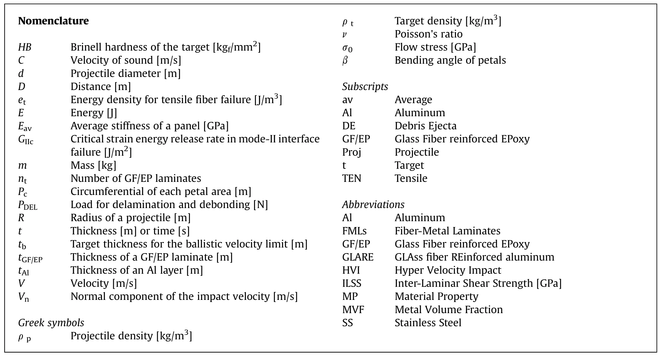
Nomenclature HB Brinell hardness of the target [kgf/mm2]C Velocity of sound [m/s]d Projectile diameter [m]D Distance [m]et Energy density for tensile fiber failure [J/m3]E Energy [J]Eav Average stiffness of a panel [GPa]GIIc Critical strain energy release rate in mode-II interface failure [J/m2]m Mass [kg]nt Number of GF/EP laminates Pc Circumferential of each petal area [m]PDEL Load for delamination and debonding [N]R Radius of a projectile [m]t Thickness [m] or time [s]tb Target thickness for the ballistic velocity limit [m]tGF/EP Thickness of a GF/EP laminate [m]tAl Thickness of an Al layer [m]V Velocity [m/s]Vn Normal component of the impact velocity[m/s]Greek symbols ρ p Projectile density [kg/m3]ρ t Target density [kg/m3]ν Poisson's ratio σ0 Flow stress[GPa]β Bending angle of petals Subscripts av Average Al Aluminum DE Debris Ejecta GF/EP Glass Fiber reinforced EPoxy Proj Projectile t Target TEN Tensile Abbreviations Al Aluminum FMLs Fiber-Metal Laminates GF/EP Glass Fiber reinforced EPoxy GLARE GLAss fiber REinforced aluminum HVI Hyper Velocity Impact ILSS Inter-Laminar Shear Strength[GPa]MP Material Property MVF Metal Volume Fraction SS Stainless Steel
GLARE offers a superior impact resistance by distributing the transverse impact load in the in-plane direction.GLARE,therefore,incurs a larger flexural displacement compared to that incurred by a bare Al plate[11].The outer Al skins of a GLARE panel compensate for the insufficient transverse strength of GF/EP composite laminates [9]. The Al skin at the impact site dampens the impact load,while stretching and thinning of the Al skin at the non-impacted site stifle the delamination propagation [11]. A higher metal volume fraction (MVF) augments the energy dissipation by GLARE:GLARE 5-2/1-0.4 grade dissipates 30%higher energy compared to that dissipated by GLARE 5-2/1-0.3 grade for identical impact energy[11,12].At a higher strain rate,GLARE offers a better impact resistance, since the tensile strength of glass fibers inclines by 25-30%at ?˙=70 s[13].The effect of strain-rate changes with the volume fraction of glass fibers and their orientation relative to the direction of the impact load.
A multiplex orientation of GF/EP plies yields a GLARE laminate able to evacuate more impact energy through inter-laminar delamination and membrane stretching of GF/EP [14]. Consequently, the cross-ply fiber-metal laminates (FMLs) demand approximately 39% higher specific perforation energy relative to that demanded by the unidirectional FMLs[15,16].
The cross-ply GLARE 5 grade encounters the highest contact resistance force, while the unidirectional [90] GLARE grade experiences the lowest one for comparable ballistic impact energy[17]. Upon impact, the cross-ply GLARE grade transfers also a substantial fraction of its kinetic energy into the strain energy.Delamination is not apparent in unidirectional composite laminates, since the inter-laminar shear stresses are not appreciable.The cross-ply and the quasi-isotropic counterparts,by comparison,experience delamination.
Thinner GLARE laminates evacuate the impact energy preferably through permanent global deformation because of their relatively lower bending stiffness[14].By contrast,a thicker GLARE laminate is stiffer out-of-plane and dissipates the impact energy primarily in material damage.In correspondence,the damage of a GLARE 5-4/3 laminate, including debonding and shear failure of Al layers, is larger compared to the damage of a GLARE 5-3/2 laminate for identical impact energy.
For a blast impulse,thicker FMLs succumb to ring buckling at the front(impact site)Al skin and debonding at the rear(non-impacted site)Al skin[18].They require a larger blast impulse to undergo the same flexural displacement as that of thinner FMLs, while suffer more damage in the form of fiber breakage,Al rupture,and rippling[19].The sound-wave speed in glass fibers is four times the soundwave speed in epoxy resin[18].The contour of rear face debonding favors the fiber direction, therefore.
1.3. Next step
The literature review exhibited many studies, which have interrogated the blast- and the high-velocity impact resistance of GLARE. It is to be noted that a systematic approach to make the GLARE laminate fit for a meteoroid bumper shield has not been investigated,if any,has not been made available for public release.Against this backdrop, an experimental campaign has been conducted within the available scope of this study, to investigate the response of dissimilar GLARE configurations to the HVI of 2 mm diameter sphere projectiles launched at velocities up to 7.15 km/s.The main aim of this study is to demarcate the potential GLARE candidates able to defeat micrometeoroids below and beyond the ballistic limit (BL). In this pursuit, this paper, first, lends detailed insights into the GLARE damage mechanism upon impact with micrometeoroid analogs; next, employs simple matrices to apportion the impact energy between different damage modes of GLARE;and finally, discriminates between different GLARE configurations based on the dissipated energy. Because, higher the energy dissipates in the plastic damage of a bumper shield, lower will be the imparted energy on a hull structure.
2. Methodology
2.1. Particulars of experiments
2.1.1. GLARE panel manufacture
The GLARE panels accommodated S2-glass fiber reinforced FM94-epoxy laminates stacked alternately between 2024-T3 Al alloy sheets.The GF/EP ply and the Al sheet were 0.125 and 0.4 mm thick, respectively. The rolling direction of Al sheets was aligned with the fiber direction of mating GF/EP plies. A chromate coating on the Al sheets promoted their adhesion with the GF/EP plies.The material layers were stacked in the required sequence manually(see Fig.1a) and cured in an autoclave for 3 h at a curing temperature of 120C under 6 bar pressure(see Fig.1b).Square specimens,in dimension 100 mm × 100 mm, were cut using a diamond saw afterwards. Ultrasonic C-scan of the GLARE specimens elucidated no manufacturing-induced flaws or cutting-induced edge defects(delamination or debonding). Finally, four circular holes were drilled at four corners 1 cm away from the specimen edge to mount the GLARE specimens on the hatch of the test chamber.
2.1.2. GLARE configurations
Five thick GLARE configurations were considered.GLARE 3-12/11-0.2, 3-8/7-0.4, 5-6/5-0.4, quasi-isotropic 6/5-0.4, and unidirectional 9/8-0.4 were denoted,respectively,as A,B,C,D,and E in Table 1. The nomenclature of GLARE reads:
· GLARE grade - number of Al layers/number of GF/EP laminates in the stacking sequence - thickness of an Al layer.
· Grades 3 and 5 stand for the cross-ply orientation of laminas in a GF/EP laminate. It must be emphasized that grade 3 includes two plies in a cross-ply GF/EP laminate,while each cross-ply GF/EP laminate of grade 5 has four plies.
· In accordance, GLARE 3-12/11-0.2 stands for GLARE grade 3-12 Al layers/11 cross-ply GF/EP laminates in the stacking sequence - 0.2 mm thick Al layer. The nomenclature of other GLARE configurations can be detailed using the identical approach.
The GLARE configurations had a thickness of approximately 5 mm. Looking at Table 1, dissimilarity between the GLARE configurations was discernible regarding the metal volume fraction(MVF),the GF/EP ply orientation,and the number of material layers.The reference GLARE-C configuration was the standard GLARE 5 grade. GLARE-A configuration was akin to the standard GLARE 3 grade and comprised nearly the same MVF as that of GLARE-C configuration. Yet, GLARE-A configuration had 2.09 times the material layers of GLARE-C configuration. GLARE-B configuration emulated GLARE-A configuration.GLARE-B configuration,however,had a 0.18 higher MVF and eight less material layers compared to that of GLARE-A configuration.GLARE-D and E configurations were customarily designed for this study.GLARE-E configuration had the highest MVF of 0.78. GLARE-D configuration resembled GLARE-C configuration in all design aspects, albeit the ply orientation of their GF/EP laminates was dissimilar. The GF/EP ply orientation of GLARE-A, B, and C configurations was cross-ply,while of GLARE-D configuration was quasi-isotropic.Table 1 exemplifies the physical characteristics of the aforementioned GLARE configurations.
2.1.3. Test instruments
A two-stage light-gas gun was employed to conduct the HVI experiments at room temperature and 50% relative humidity. Helium was used as the propellant.Fig.2 outlines the basic lay-out of the gas gun, and Fig. 3a shows the mounting hatch of the GLARE specimen.At the end of the target chamber,four bars on the hatch kept the GLARE plate fixed against the projectile. A witness plate,placed 60 mm downstream of the GLARE plate, collected the downrange debris ejecta,which comprised projectile remnants and disrupted GLARE materials. A vibration sensor on the GLARE plate verified the projectile velocity determined by the laser beams. An identical sensor on the witness plate helped measuring the impingement velocity of the downrange debris ejecta. High-speed videos of the HVI events could not be captured, since a million frames per second camera was not available during the experimental campaign. The explosive nature of HVI destroyed the attached thermocouples on GLARE a couple of times. To avoid further damage of the test assets, the test plan did not include measuring the temperature of GLARE specimens upon HVI. The projectile was launched with an initial velocity at an incidence obliquity of 0relative to the normal of the GLARE front face. The 0angle of projectile incidence was chosen to make sure the most transfer of projectile momentum to the GLARE target.
2.1.4. Ballistic limit of GLARE
The modified Cour-Palais equation (MCPE) was applied to approximate the BL of the selected GLARE configurations. The MCPE was developed for the HVI of Al projectiles on Al targets[20],yet, could be used for the GLARE configurations, since they comprised a significant MVF. The MCPE reads [20]:
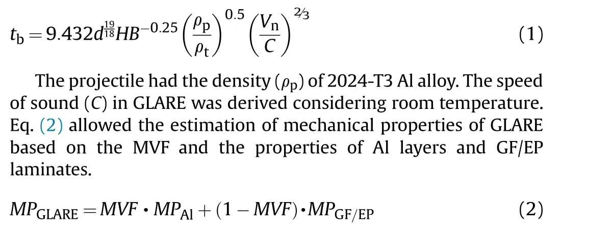
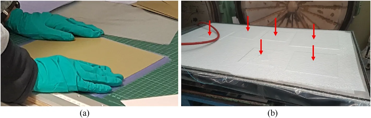
Fig.1. (a)Hand lay-up of a GLARE laminate;(b)a breather fabric and an air-tight plastic foil covering the GLARE laminates on the stainless steel bed of the autoclave prior to curing;red arrows indicate the location of GLARE laminates.
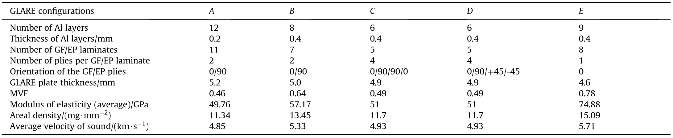
Table 1 The GLARE configurations.
Fig. 2. Schematic side-view of the two-stage light-gas gun.
Fig. 4 shows that GLARE-B configuration had the highest BL of 6.52 km/s. GLARE-C and D configurations possessed the same BL(5.9 km/s)attributed to their identical panel properties.Therefore,in most of the experiments,an impact velocity(V)of 5.5 or 7 km/s was favored to compare the energy dissipated in the partial- and the full perforation events of GLARE.
2.1.5. Test matrix
Fig. 4. Ballistic limit of the GLARE configurations determined using a 2 mm dia Al projectile in the modified Cour-Palais equation.
Keeping the Vand the GLARE configuration, Al and stainless steel (SS) projectiles were selected to discriminate between the damage extents of GLARE for the HVI of variably dense micrometeoroid analogs. The experiments employed 2 mm dia sphere projectiles. The size of the fragment-simulating projectiles represented micrometeoroids, which don't leave a luminous trail in the space environment [21]. One SS projectile was dislodged at V=2 km/s to interrogate the response of GLARE to the impact of a highly dense micrometeoroid at a lower V. Total 14 experiments were performed. Table 2 shows the experimental conditions and the outcomes of the experimental campaign. To determine the standard deviation of measurements, four extra GLARE-C specimens had been impacted at V=5.6 and 7 km/s(two specimens for each V)with 2 mm dia Al projectiles.Keeping the Vnear identical,the captured downrange debris mass (on the witness plate) from two comparable experiments showed a maximum difference of ± 1.5%, the number of petals varied by± 2 in the front-and the rear face of an impacted GLARE specimen, and the corresponding maximum difference of the downrange debris velocity was ±1.8%.The author acknowledges that the randomicity of HVI experiments and the related deviation of experimentally determined values depend on the calibration of the experimental set-up. Fine tuning of the gas gun is imperative to reproduce the experiments and dislodge the projectile over the required flight trajectory to impact the GLARE target exactly in the middle. On top of that, a wellcontrolled manufacturing process of GLARE is required to circumvent the manufacturing-induced flaws and their influence on the disparity of damage modes of GLARE.
Fig.3. (a)The mounting hatch;(b)a GLARE specimen subjected to HVI;1 and 2 stand for the mounting bar and the Al witness plate,respectively;3 denotes a GLARE plate on the mounting bars; 4 indicates the location of bored holes.
Table 2 Conditions of HVI experiments.
2.1.6. Velocity measurement
Two wide beam lasers, positioned perpendicular to the projectile trajectory, measured the projectile velocity (V) at an accuracy within±0.01 km/s(see Figs.2 and 5).A vibration sensor on the witness plate signalized the moment, at which the downrange debris ejecta impinged on. The velocity of the downrange debris ejecta (V) was determined using Eq. (3) that required the travel time (t= D/V) of the velocity signal from the laser (L2)to the target plate(TP),next to the witness plate(t),and finally,to the vibration sensor (s) on the witness plate (t= D/C)(see Fig.5).To measure the velocity of the downrange debris ejecta,the transmission velocity of the impingement impulse through the Al witness plate was assumed akin to the bulk sound velocity(C)in 2024-T3 Al alloy.
where tis the time span between the first signal from the laser(L2) and the second signal from the vibration sensor (s) on the witness plate; D denotes the distance between the corresponding positions.
2.1.7. Mass of debris ejecta
Fig. 5. Laser and sensor positions to measure the velocity of the projectile and the downrange debris ejecta;DL2-TP stands for the distance between the laser(L2)and the target plate;DTP-WP is the distance between the target plate and the witness plate;Vproj and VDE are the velocity of the projectile and the downrange debris ejecta,respectively.
The material mass erupted from a GLARE laminate and the mass of a projectile contributed to the total debris mass. Since the selected GLARE configurations were thick enough, the rarefaction wave,reflected from the rear face of the GLARE laminates,could not overtake and weaken the shock-wave inside the projectile.Besides,the impact velocities were in proximity to the threshold velocity of 6.5 km/s[22],generating a shock-wave pressure in excess of 65 GPa and consequently, entirely melting and partially vaporizing the 2 mm dia Al projectiles [23]. Blackish hue in the front face of the impacted GLARE laminates ascertained the vaporization of the Al projectiles and the carbonization and the sublimation of epoxy resin. The Al projectile mass, therefore, was not considered in the total debris mass. By comparison, the GLARE laminates could degrade the SS projectiles only in part. Beyond and below the BL(see Fig. 4), solid fragments of the SS projectiles perforated the GLARE laminates.Several SS fragments,ejected roughly parallel to the impact direction,were found stuck in the narrow craters of the Al witness plate.SS fragments with a larger scatter angle bypassed the witness plate and were later collected from the target chamber.The mass of the SS fragments, as a result, could be included in the total debris mass. Independent of the projectile material, the difference in the mass of a GLARE laminate prior and posterior to a HVI experiment resulted in the material mass dismantled from that GLARE laminate. This approach of determining the mass of the debris ejecta worked for the partial-and the full perforation events of the GLARE laminates(see Table 3),wherein the velocity and the mass of the debris ejecta determined the fraction of the impact energy transferred to the debris kinetic energy.For the partial-and the full perforation events,the velocity and the mass of the uprange debris ejecta were determined from numerical analysis.
One point from the foregoing experiments should be emphasized. The ratio of target thickness to projectile diameter (t/d)was around 2.5 over the entire spectrum of the conducted experiments. t/d= 2.5 was way beyond the ratio of 0.38, which is surmised as the uppermost threshold to initiate an external bubble of debris cloud behind the target plate [24,25]. Ascribed to the beyond threshold t/dratio, pronounced spalling of the GLARE laminates was apparent, and the downrange debris ejecta did not evolve like a conventional well-developed debris cloud that contains particles clustered in a thin frontal disk.In the full perforation events, the downrage debris ejecta comprised solid fragments ofrear Al layers and GF/EP fibers dislodged in narrow coloumns without an outer veil.For a comparable V,the uprange ejecta cone,emerged from the HVI of an Al projectile on a GLARE laminate,had similar features to that of the uprange ejecta cone generated by the HVI of an Al projectile on a thin Al target [24,26], since a 0.2-0.4 mm thick Al skin was at the front side of the GLARE laminates.
Table 3 Mass of the downrange debris ejecta.
3. Experimetal results
The upcoming discourse demarcates the damage extents of GLARE based on the physical characteristics of the impacting projectiles and the design variables of the GLARE configurations.
3.1. Projectile- velocity and mass
The experiments demonstrated an enlargement of the damage area with an increase of V. A 2 mm dia Al projectile launched at V= 5.6 km/s partially perforated GLARE-B4 configuration (see Fig. 6a). The pierced hole of GLARE-B4 configuration exhibited tensile failure of glass fibers. The rear Al skin debonded from the mating GF/EP laminate,since the shock-wave reflected as a releasewave through the farthest Al-GF/EP interface and as a result, the critical failure stresses of this interface were reached. After debonding,the rear Al skin experienced further stretching,became thinner, and finally, was ruptured. The major axis of the elliptical crack of the rear Al skin was aligned with the 0fiber direction of the mating GF/EP ply. When the Vincreased to 6.94 km/s, the Al projectile ruptured the rear GF/EP laminates(see Fig.6b).The rear Al skin petalled preferably in the fiber direction of the mating GF/EP ply, since the fiber direction exerted a lower friction compared to that imposed by the transverse-fiber direction. The rear petalled area appeared in a rectangular shape, albeit being elliptical at V= 5.6 km/s. Epoxy sublimated from the damage area. Resin sublimation singled out the ruptured fibers. No fibers clung to the petalled surfaces,indicating that the rear Al skin debonded prior to petalling.Keeping the Vat 5.6 km/s,petalling and fiber breakage of GLARE were significant when the SS projectile replaced the Al one(compare Fig. 6c-a). Besides, for the HVI of a SS projectile, the momentum imbalance and the shear stress ripped off the tips of large petals and multiplied them around a near circular damage area (see Table 4). Bending, rupture, and petalling of the inner Al layers exacerbated the fiber breakage (see Fig. 6c). Concomitant with the rear face failure,the front face succumbed to more damage for the HVI of a highly dense projectile(compare Fig.6f-d,and see Table 4).
It is of interest to note that the combined effect of impact and explosion caused the front face petals.First,the projectile created a tiny hole in the thin Al skin. Next, the shock-wave pressure burst opened the Al skin. Impulsive opening of the Al skin induced high circumferential strains in the Al material,causing radial cracks and subsequent rotation of the affected material.The material rotation and the progresssive plastic tearing of the Al skin resulted into the front face petals around the pierced hole. Bending deformation of the petals propagated the hinge line with decreasing local curvature. In addition, the GF/EP laminates endured through-thethickness expansion due to the volumetric decompression and the outward flux of sublimated epoxy. The appearance of the ruptured front face tended toward that of a typical ear face, as a result.
Fig. 6. Damage at the rear- and the front side of GLARE-B laminates for a dissimilar projectile velocity and projectile mass.
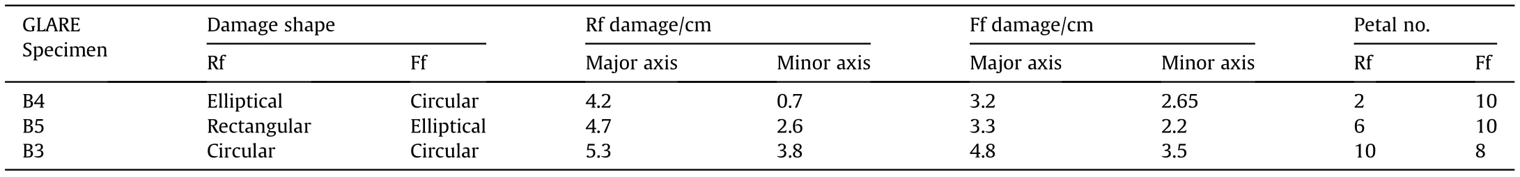
Table 4 HVI damage of GLARE-B configuration.
3.2. Number of material layers
The shock-wave reflects at the Al-GF/EP debonding interfaces.More material layers impose more inter-laminar interfaces, thus,attenuate the shock-wave pressure away from the impact site.That means, the distal material layers suffer a lower level of damage,since they experience lower HVI-induced stresses. In agreement,GLARE-A configuration was partially perforated for the impact of a 2 mm dia Al projectile at V= 5.7 km/s. Because, GLARE-A configuration had twenty two debonding interfaces due to its twelve Al layers and eleven GF/EP laminates.However,a comparable impact of a 2 mm dia Al projectile tunneled a hole through the entire thickness of GLARE-C configuration, which had ten debonding interfaces ascribed to its six Al layers and five GF/EP laminates(compare Fig. 7a against 7d).
GLARE-A configuration dissipated the impact energy in large petals (see Fig. 7b and c). The rear face petals multiplied at V= 7.15 km/s (compare Fig. 7b-a) and circumscribed a smaller damage area compared to the rear face damage area of GLARE-C configuration for the near identical HVI (compare Fig. 7b-e, and see Table 5).Of note,the rear face petals of GLARE-A configuration circumscribed a larger damage area for the impact of a SS projectile instead of an Al one at V=5.45 km/s(compare Fig.7c-a,and see Table 5). A comparable impact of a 2 mm dia SS projectile suppressed the rear face damage area of GLARE-C configuration, by contrast (compare Fig. 7f-c). The outer Al skins of GLARE-A configuration debonded preferably in the fiber direction of the GF/EP ply beneath(see Fig.7c and i).Looking at Fig.7c and i,it can be anticipated that the beneficial effect of a higher number of material layers of GLARE-A configuration was offset to an extent by the lower bending stiffness of its 0.2 mm thick Al layers,which had half of the bending stiffness of 0.4 mm thick Al layers of GLARE-C configuration. This outcomes suggest thicker outer Al skins and thinner inner Al layers to develop a HVI resistant GLARE better than GLARE-A and C variants.
Keeping the Al projectile, the front face petals of GLARE-A configuration rolled further in the fiber direction when the Vincreased from 5.7 to 7.15 km/s (compare Fig. 7h-g). GLARE-C configuration exhibited also a similar trend of front face petalling for a comparable increase of V(compare Fig.7k-j),albeit the fiber failure of GLARE-C configuration was not as severe as that of GLARE-A configuration (compare Fig. 7k-h). The HVI of a SS projectile, in place of an Al one, reinforced the Al-GF/EP interface stresses to circumvent the interface friction in the fiber- and the transverse-fiber direction. The front face petals of GLARE-C configuration circumscribed a larger elliptical damage area for the HVI of a SS projectile(compare Fig.7l-j,and see Table 5),as a result.
3.3. Stacking sequence
The GF/EP laminates attenuate the shock-wave pressure away from the impact site,since the intra-laminar fiber/matrix interfaces promote the reflection of a shock-wave. The mismatch of ply orientation reinforces the wave interaction. As followings, the shock-wave traverses a limited area.The dissimilar impact damage of GLARE-C3 and D3 configurations corroborates the influence of wave interweaves on the damage evolution. GLARE-D3 configuration had the quasi-isotropic GF/EP laminates. By comparison, the GF/EP laminates of GLARE-C3 configuration were of cross-ply type,which resulted in a slightly larger damage area compared to that of GLARE-D3 configuration for the comparable impact energy(compare Fig. 8a-b, and see Table 6). However, GLARE-D3 configuration suffered a higher severity of material damage, since its quasi-isotropic GF/EP laminates suppressed the shock-wave expansion and helped directing the shock-wave energy to a limited area. Similar to GLARE-D3 configuration, GLARE-B3 configuration suffered extensive fiber breakage, since the amplitude of stress waves exceeded the limit threshold in the fiber direction(see Fig.8c and f).Despite the disparity of the damage area and the degree of material damage,a one-to-one comparison of the GLARE laminates (demonstrated in Fig. 8) would be ambiguous.Because, GLARE-B3 configuration had only two plies per GF/EP laminate against four plies per GF/EP laminate of GLARE-D3 and C3 configurations. Based on the findings, it can be concluded that a multiplex ply orientation augments the material damage in the impact zone. On the other hand, a unidirectional ply orientation enlarges the circumferential area of precarious material damage.
3.4. Dispersion of projectile momentum
GF/EP laminates of GLARE deplete the axial momentum of a projectile through membrane stretching. Numerous bidirectional(0/90)GF/EP plies stiffen a cross-ply GLARE and help dispersing a fragmented projectile in the radial direction.In conformity,the HVI of an Al projectile at V= 5.7 km/s inscribed a non-visible hole at the distal side of GLARE-A/1 configuration, since GLARE-A/1 configuration had twenty-two GF/EP plies in cross-ply orientation(see Fig.9a),which were eight more than the fourteen GF/EP plies of GLARE-B4 configuration. Besides, the fiber- and the matrix damage of the frontal GF/EP plies of GLARE-A/1 configuration (see Fig. 9c) dissipated the impact energy in part and decelerated the fragmented projectile downstream to the GLARE rear face. By comparison, a similar impact partially perforated GLARE-B4 configuration (compare Fig. 9b-a, and see Table 7), despite both GLARE-B4 and A/1 configurations had two plies per cross-ply GF/EP laminate.This outcome suggests using a higher volume fraction of GF/EP plies compared to that of Al layers to render a GLARE laminate HVI resistant and make a projectile dispensable.
4. Analytical approximation of energy dissipation
4.1. Kinetic energy of downrange debris ejecta
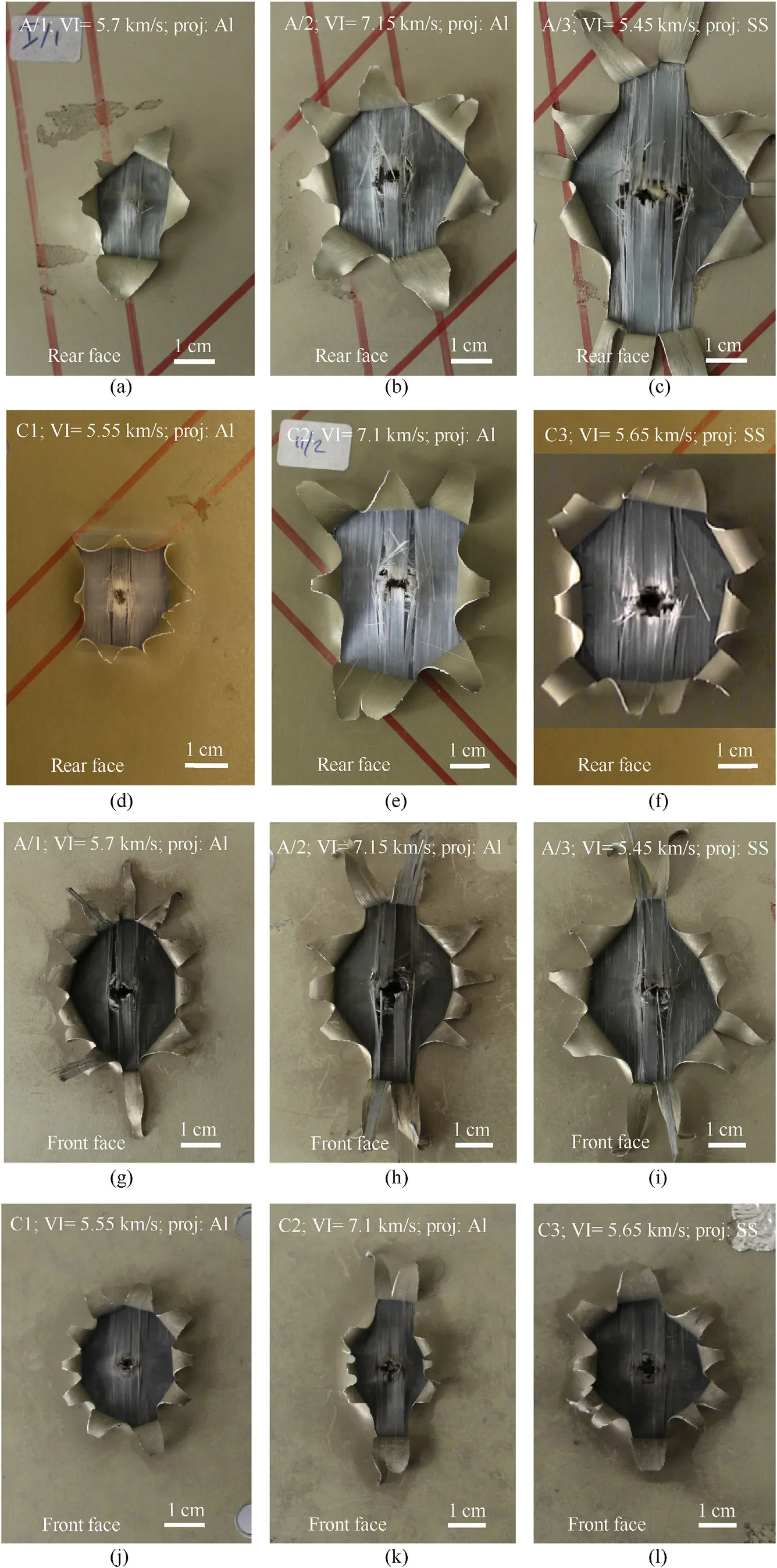
Fig. 7. Damage at the rear- and the front side of GLARE-A and C laminates for a dissimilar projectile velocity and projectile mass.
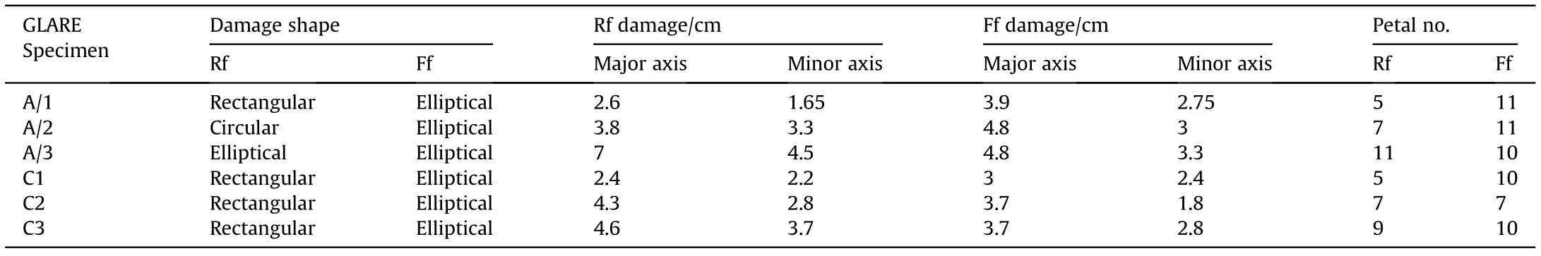
Table 5 HVI damage of GLARE-A and C configurations.
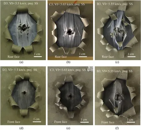
Fig. 8. Damage at the rear- and the front side of GLARE-B3, C3 and D3 laminates for comparable impact energy.
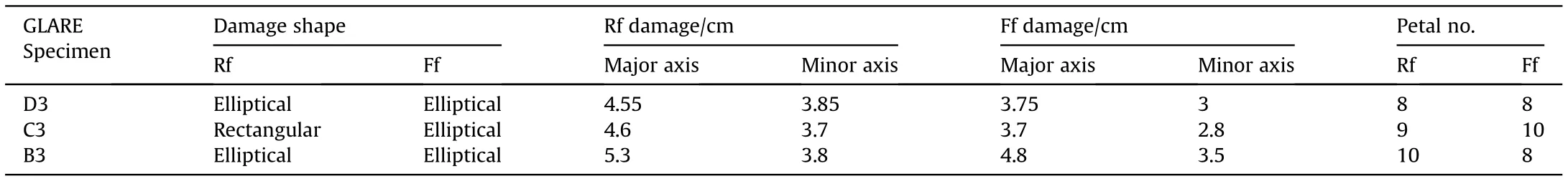
Table 6 HVI damage of GLARE-B3, C3 and D3 configurations.
As seen in Fig. 10a, a 2 mm dia SS projectile, when impacted GLARE-B3, C3 and D3 configurations at V= 5.5 km/s, dislodged a downrange debris ejecta with an approximate axial velocity of 2.2 km/s, which was about 1.4 km/s higher than the downrange debris velocity generated by the impact of a 2 mm dia Al projectile on GLARE-B4, D5 and E4 configurations at V= 5.6 km/s. Keeping the Al projectile,the downrange debris velocity did not undergo an appreciable change when the Vinclined from 5.5 to 7 km/s(compare B4, D5, E4 to A/2, B5, C2), since the radial dispersion of the debris momentum approached toward an asymptote beyond the BL. This outcomes imply that the front Al skin crushed the Al projectile and helped the underlying GF/EP laminates to reduce the momentum of projectile remnants. By contrast, the SS projectile was fragmented into splinters upon HVI. The splinters were dislodged downrange with an appreciable axial momentum. Kinetic energy of the downrange debris ejecta was inferred from:
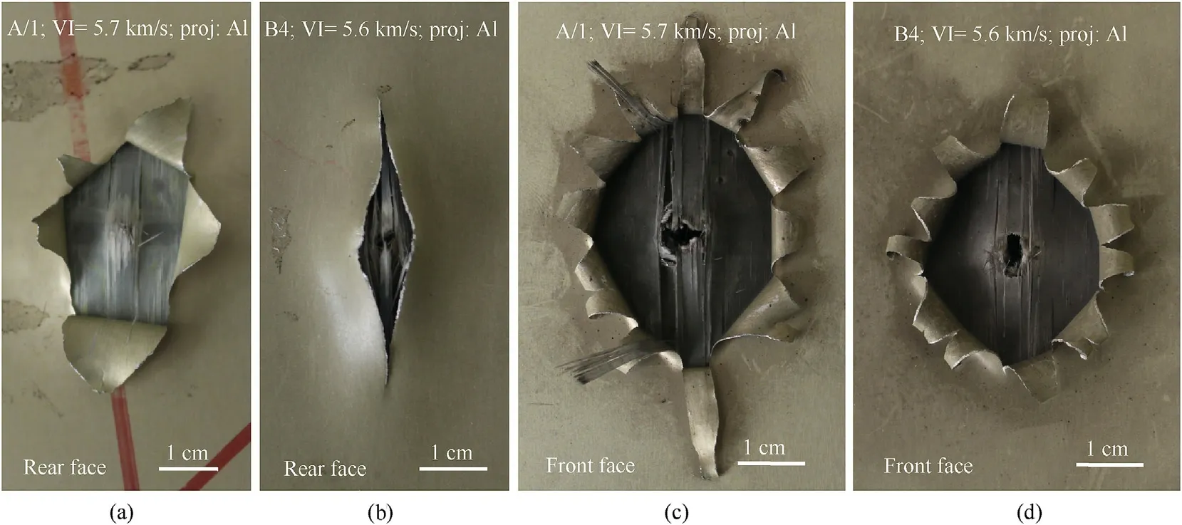
Fig. 9. Damage at the rear- and the front side of GLARE-A/1 and B4 laminates for comparable impact energy.

Table 7 HVI damage of GLARE-A/1 and B4 configurations.

Fig.10. Velocity and kinetic energy of the downrange debris ejecta.

using the mass and the velocity of the downrange debris ejecta exemplified in Table 3 and Fig.10a, respectively.
Independent of the V(within the hypervelocity regime)and the GLARE configuration, the kinetic energy of the downrange debris ejecta was on an average only 2%of the impact energy,if a 2 mm dia Al projectile impacted GLARE (see Fig. 10b). That means the Al projectile was pulverized and vaporized at the impact site, which helped the GF/EP laminates underneath to diffuse the projectile momentum before the GF/EP laminates got pierced.By comparison,the HVI of a 2 mm dia SS projectile on GLARE-B3 configuration at V=5.55 km/s allocated 17.76%of the impact energy to the kinetic energy of the downrange debris ejecta. For the HVI of a SS projectile, it was anticipated that the GLARE laminates could not deplete the projectile momentum, became energy saturated, and consequently,were easily perforated by the partially fragmented SS projectile.
Of note,GLARE-C3 and D3 configurations had an identical MVF and an equal number of GF/EP plies.The velocity of the downrange debris ejecta discharged from GLARE-D3 configuration, yet, was 250 m/s lower than the velocity of the downrange debris ejecta dislodged from GLARE-C3 configuration for the comparable impact energy. This suggests that the quasi-isotropic GF/EP laminates of GLARE-D3 configuration allowed a relatively weaker reflection of the shock-wave at the GLARE rear face.However,the kinetic energy of the downrange debris ejecta discharged from GLARE-D3 configuration was 2.38 times the kinetic energy of the downrange debris ejecta emanated from GLARE-C3 configuration,owing to the relatively three times greater downrange debris mass erupted from GLARE-D3 configuration.
4.2. Delamination and debonding energy
The exact delamination or debonding energy of GLARE can barely be approximated conducting experiments. To alleviate this shortcoming, Hoo Fatt et al. [27] proposed an analytical method able to predict the fraction of impact energy dissipates in the interlaminar interface failure of GLARE. They assumed large energy dissipation in delamination propagation (rather than in delamination onset) in the sliding shear mode (mode-II). The delamination force reads [27]:
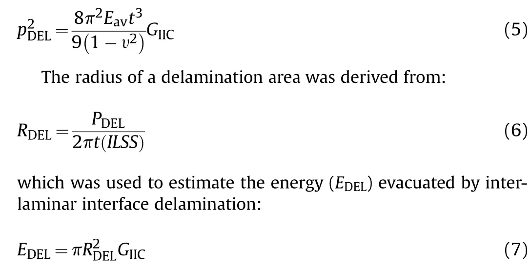
This study adopted the analytical approach of Hoo Fatt et al.[27]to estimate the failure energy of GLARE inter-laminar interfaces.As seen in Fig.11,the assessed GLARE configurations demanded nearly alike interface failure energy (sum of the debonding- and the delamination energy):on an average 8.61 J,which constituted 3%of the impact energy of a 2 mm dia Al projectile dislodged at 7.1 km/s.Among the investigated GLARE configurations, GLARE-E configuration dissipated the highest 10.7 J energy in the failure of interlaminar interfaces due in part to its highest MVF-related elastic modulus (74.88 GPa) (see Table 1), which reinforced the shear modulus and the related shear stress limit of inter-laminar interfaces. Although, GLARE-E configuration exhibited only debonding due to its single unidirectional ply per GF/EP laminate.Ascribed to the thirty three inter-laminar interfaces (delamination- and debonding interfaces), GLARE-A configuration dissipated 8.02 J energy in the interface failure,even though,the elastic modulus of GLARE-A configuration was the lowest compared to that of other GLARE configurations.GLARE-C and D configurations possessed an identical elastic modulus and plate thickness, albeit the ply orientation of their GF/EP laminates was dissimilar. They demanded similar energy (7.75 J) for the failure of inter-laminar interfaces,therefore.
It must be emphasized that Eq. (5) was developed to infer the inter-laminar fracture toughness of composite laminates for a low velocity impact event. Yet, when a thin target deflects to a large extent like in a blast- or a HVI event, the membrane stretching resistance is much greater than the bending resistance of the target,and the inter-laminar fracture toughness does not alter the membrane stiffness.Because,beyond the hyperstrain rate(e.g.,10s),the inter-laminar fracture toughness tends toward an asymptote.In conformity, the energy, dissipated in the inter-laminar interface failure of the chosen GLARE configurations,also approached a near asymptotic value(see Fig.11),since preferably other damage modes dissipated the impact energy. Eq. (5) could capture this interface failure energy asymptote successfully, justifying its implementation for the HVI regime.
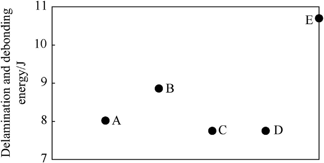
Fig. 11. Energy dissipation in the delamination and debonding of different GLARE configurations.
4.3. Petalling energy
A couple of analytical methods have been proposed in the previous literature [27,28] to measure the petalling energy. In this study, the total petalling energy of a GLARE laminate was inferred from(Ref. [27]):

For Eq.(8),it was assumed that the dynamic flow stress(σ)and the static flow stress of Al were identical,since the flow stress of Al is relatively insensitive to the strain-rate.Although,the ductility of Al declines remarkably with the increase of strain-rate.Among the experiments of this study,only the HVI of a 2 mm dia SS projectile on GLARE-B3 configuration at V= 5.55 km/s demonstrated discernible petalling of the inner Al layers.Petalling of the inner Al layers was not appreciable in the HVI events of other GLARE configurations.The petals of GLARE-A configuration bent over an angle of θ = π. Other GLARE configurations incurred petals bent over θ =π/2.
Fig.12 illustrates the energy budget for petalling the different GLARE configurations. As found, GLARE-D5 configuration demanded a large fraction of the impact energy for petalling (21.64 J,approximately 12% of the impact energy). GLARE-C3 and D3 configurations demanded nearly an equal fraction (22 J, 4.3%) of the impact energy for petalling,attributed to their identical MVF and Al layer thickness.Keeping the V,the HVI of a SS projectile(in the HVI event of GLARE-D3 configuration) instead of an Al one (in the HVI event of GLARE-D5 configuration) declined the normalized petalling energy by 7.8%. The corresponding change in the normalized petalling energy was just 1% for GLARE-B configuration (compare B4 configuration impacted with an Al projectile to B3 configuration impacted with a SS projectile).Because,GLARE-B configuration had the momentum imbalance unchanged due to its two more 0.4 mm thick Al layers compared to the number of 0.4 mm thick Al layers of GLARE-D configuration. Keeping the Al projectile, the normalized petalling energy decreased with the increase of V(compare C1 configuration impacted at V= 5.55 km/s to C2 configuration impacted at V= 7.1 km/s). This suggests the preponderance of other damage modes, e.g., bulk material failure, in the higher HVI energy regime. It is worth emphasizing that for the higher HVI energy regime, GLARE-B configuration exhibited the best performance in terms of the normalized petalling energy. GLARE-D configuration was superior in the lower HVI energy regime.
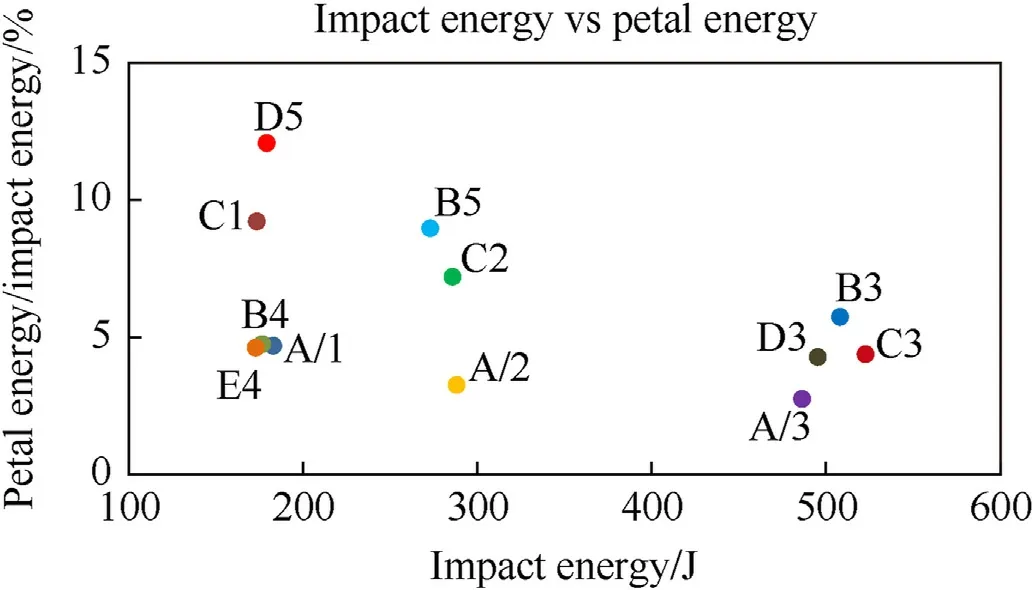
Fig.12. Petalling energy of different GLARE configurations.
4.4. Tensile failure energy
Eq. (9), proposed by Hoo Fatt et al. [27], was implemented to approximate the energy dissipated in the tensile failure of GF/EP laminates of GLARE. This approach considers a cylindrical hole being left by the tensile fiber failure and the perforation of a GF/EP laminate,while the volumetric strain of a GF/EP laminate dissipates the impact energy only partially.

The tensile fiber failure of a GF/EP laminate demanded an energy density(e)of 28.9 MJ/m[27].Thus,according to Eq.(9),the GLARE configurations demanded an energy maximum of 1 J for the tensile failure of their constituent GF/EP laminates (see Fig.13).
Among the investigated GLARE configurations, GLARE-A configuration accommodated the highest number (twenty two) of GF/EP plies. GLARE-A configuration, therefore, dissipated comparatively the highest energy (0.99 J) in the tensile splitting of GF/EP laminates. By comparison, GLARE-E configuration had the lowest number(eight)of GF/EP plies,thus,demanded a mere 0.36 J for the tensile failure of GF/EP laminates. GLARE-C and D configurations dissipated identical energy (0.9 J) in the tensile failure of GF/EP laminates,since both configurations had twenty GF/EP plies.It was found that the GLARE configurations dissipated a negligible percent of the impact energy in the tensile failure of GF/EP laminates.
4.5. Residual energy
Remainder of the impact energy, dissipated in the bending,membrane stretching, vibration, wave interference, increase of entropy,and sublimation of epoxy,was collectively denoted here as residual energy. Looking at Fig.14, the HVI of a 2 mm dia SS projectile on GLARE-D3 configuration at V= 5.5 km/s dissipated 68.73%of the impact energy in the residual modes.68.73%was the lowest relative to that dispensed by other GLARE configurations in the residual modes. Because, the HVI event of GLARE-D3 configuration allocated about 25.23% of the impact energy to the kinetic energy of the downrange debris ejecta, which was the highest measured in the experimental campaign.For a comparable impact condition, in terms of the normalized residual energy, GLARE-C3 configuration dissipated 15.2% higher energy compared to that dispensed by GLARE-D3 configuration. The difference between GLARE-C3 and D3 configurations regarding the normalized residual energy attributed to the mismatch in the ply orientation and the stacking sequence of their GF/EP laminates. Due to the symmetric stacking sequence of the cross-ply GF/EP laminates, GLARE-C3 configuration could bend relatively to a larger extent without coupling its other deformation modes. By contrast, the quasiisotropic GF/EP laminates of GLARE-D3 configuration were asymmetric about their mid-plane.It is of interest to note that in terms of the normalized residual energy,the delineated mismatch between these two GLARE configurations got narrower(compare GLARE-D5 to C1), when the Al projectile replaced the SS one.

Fig.13. Energy dissipated in the tensile failure of GF/EP laminates of GLARE.
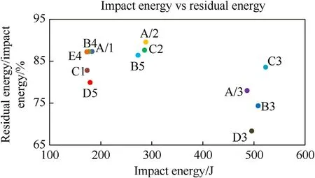
Fig.14. Residual energy budget of different GLARE configurations.
For the HVI of a 2 mm dia SS projectile at V=5.45 km/s,GLAREA/3 configuration allocated 78.4% of the impact energy to the residual modes,which was 3.77%higher(in terms of the normalized residual energy)than that dispensed by GLARE-B3 configuration in the corresponding modes. Because, comparatively eight more GF/EP plies of GLARE-A/3 configuration reinforced the membrane stretching. Looking at the normalized residual energy, GLARE-A/2 and B5 configurations exhibited a similar mismatch for the HVI of a 2 mm dia Al projectile at approximately V=7 km/s.Keeping the Al projectile, the decrease of Vto 5.6 km/s did not significantly change the normalized residual energy budget of GLARE-A and B configurations (compare A/1 to A/2, and B4 to B5).
5. The potential GLARE bumper shield
In the perforation events,for the HVI of a 2 mm dia SS projectile at V=5.65 km/s,GLARE-C3 configuration dissipated 16.06%of the impact energy in the primary damage modes (see sections 3.1 to 3.4). Note that the debris kinetic energy was included in the energy dissipated in the primary damage modes of GLARE. These energy budget for the primary damage modes of GLARE-C3 configuration was nearly half of the energy budget for the corresponding damage modes of GLARE-D3 configuration. As a result,the severity of material damage of GLARE-C3 configuration was relatively lower, although, the damage enveloped a slightly larger area compared to the damage area of GLARE-D3 configuration. A larger damage area degrades the residual strength of GLARE.GLARE-D configuration is believed to be the right candidate for a meteoroid bumper shield regarding the fail-safe structural concept,therefore. However, the HVI event of GLARE-D3 configuration dislodged a downrange debris ejecta with 138%higher kinetic energy compared to the kinetic energy of the downrange debris ejecta emerged from the HVI event of GLARE-C3 configuration.
Now, look at the partial perforation events: GLARE-B4 configuration had fourteen GF/EP plies that were eight less than the number of GF/EP plies of GLARE-A/1 configuration.Yet,ascribed to the 0.18 higher MVF (compared to the MVF of GLARE-A/1 configuration), GLARE-B4 configuration had a 7.41 GPa higher elastic modulus, which compensated for the lower tensile strength associated with its lower volume fraction of GF/EP.In the lower end of the hypervelocity regime, both GLARE-A/1 and B4 configurations dissipated 12%of the impact energy in the primary damage modes and apportioned a substantial 88% of the impact energy between the residual deformation and damage modes.Since GLARE-A/1 and B4 configurations were only partially perforated for the HVI of a 2 mm dia Al projectile at V= 5.6 km/s, they could be the potential candidates for spacecraft shielding systems, given that the impact energy is in the lower end of the HVI spectrum.
6. GLARE vs Al bumper shield
Literature review has yielded hundreds if not thousands of studies on various designs of Whipple shields (see Ref. [29] and references therein). Fred Whipple used a bumper in a multiwall meteoroid resistance structure to fragment a projectile and disperse the projectile momentum, which helped reducing the effect of the downrage impulse on a hull structure [30]. Numerous studies have exhibited the performance of a thin Al bumper shield in melting and vaporizing a spherical Al projectile under HVI loading [23,31]. Yet, in order to draw a reasonable comparison to the experimental measurements of this study, efforts had been given to select previously published experiments,in which roughly similar impact energy was applied on Al shields of a comparable areal density and thickness.
As seen,the HVI of a 9.5 mm dia Al projectile at V=6.62 km/s generated flaps and lips around the pierced hole on both faces of a 0.46 mm thick Al bumper[32,33].With the increase of the bumper thickness, the width of the overturned flaps increased. Overturn strained the material of the flaps excessively, causing cracks and separation of the flaps. For a t/dbeyond 0.424, a ring with a wedge-shaped cross-section developed all around the inside of the perforated hole [32]. The ring was weakly attached to the surrounding bumper sheet. By contrast, the HVI of a 2 mm dia Al projectile at an Vbetween 5.54 and 7.15 km/s inscribed no wide circular hole in the investigated GLARE laminates. Petals circumbscribed the front-and the rear face opening of a GLARE laminate.Torn glass fibers obscured the narrow piercing through the GLARE thickness. Looking at the separated fibers and the blackish hue around the piercing, pyrolysis and sublimation of epoxy were visibly distinct.
Next,focusing on the damage imparted by the downrage debris:evenly spaced radial lines(spokes)emanated from the center of the Al witness plate, if a 2.5 to 4.75 mm dia Al projectile impacted a 1 mm thick Al bumper at an Vbetween 6.626 and 7 km/s[24,25,34].Noticeably, the impulse load was evenly distributed on the Al witness plate. On the other hand, the shock-wave pressure,generated by the impact of a 2 mm dia Al projectile on a GLARE bumper at V= 5.5 km/s, declined step-wise linearly toward the GLARE rear face due to a low particle velocity in Al sheets (high impedance continuum) and a relatively higher particle velocity in GF/EP plies (low impedance continuum) (see Fig.15).
The reflected rarefaction wave,therefore,was not strong enough to reduce the volumetric compression of the Al projectile. Consequently, the Al projectile vaporized attributed to the augmented entropy. The gaseous form of epoxy and Al projectile exerted a concentric impulse load on the Al witness plate, causing plate bending.Meanwhile,spalling of the rear Al skin of GLARE launched solid Al fragments downrange, engraving countable tiny shallow craters without any crack around the center of the Al witness plate.However, solid splinters of a SS projectile caused narrow deep craters in the Al witness plate, as seen in Fig.16.
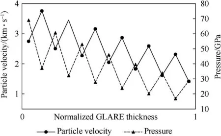
Fig.15. Shock-wave-engendered pressure and particle velocity through the thickness of a GLARE laminate; 0 and 1 of the normalized GLARE thickness stand for the front face and the rear face, respectively; the impact load was applied on the front face;VI = 5.5 km/s.
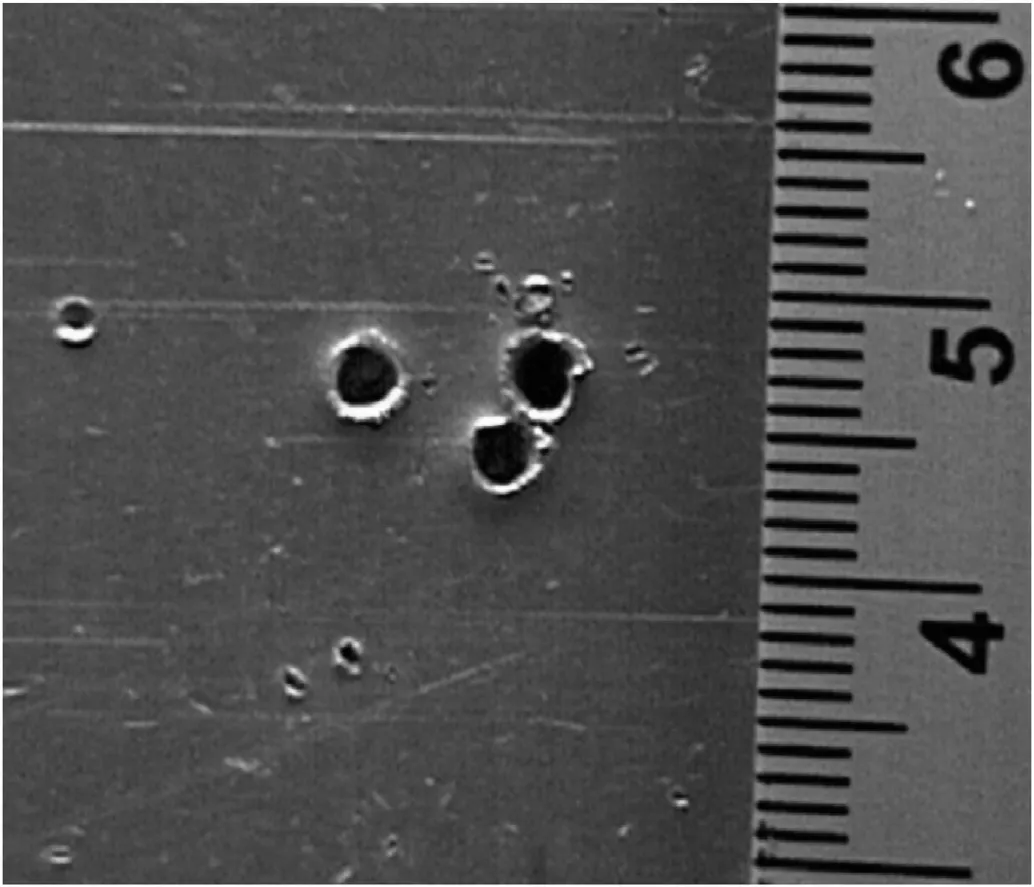
Fig. 16. Craters in the Al witness plate for the impact of a 2 mm dia stainless steel projectile on GLARE-C5 laminate at VI = 2 km/s.
If summarized, both GLARE and Al bumpers suffered plastic damage in a HVI event. However, for a comparable impact condition, the number of damage modes and the severity of material damage of a GLARE bumper were higher than that of an Al bumper.A GLARE bumper, therefore, dissipated comparatively a larger fraction of the impact energy. The extent of irreversible work transferred by a GLARE bumper suggests that the energy flux to a pressure bulkhead will be relatively lower, which makes a GLARE bumper competitive for the meteoroid shielding of spacecraft.
7. Concluding remarks
This study approximated the impact energy dissipation in the delamination and debonding of inter-laminar interfaces of GLARE,the petalling of Al layers,the tensile failure of GF/EP laminates,and the kinetics of debris ejecta. Regardless of the V(within the hypervelocity regime) and the GLARE configuration, the kinetic energy of the downrange debris ejecta was on an average 2% of the impact energy for the HVI of a 2 mm dia Al projectile. By comparison, the kinetic energy of the downrange debris ejecta comprised about 25.23%of the impact energy for the HVI of a 2 mm dia SS projectile on GLARE-D3 configuration at V= 5.5 km/s. The investigated GLARE configurations dissipated on an average 8.61 J energy in delamination and debonding,which was a mere 3%of the impact energy of a 2 mm dia Al projectile launched at 7.1 km/s.When subjected to the HVI of a 2 mm dia SS projectile at V=5.5 km/s, the quasi-isotropic GLARE configuration (configuration-D) demanded a petalling energy (22 J, approximately 4.3% of the impact energy)similar to that of the cross-ply GLARE configuration(configuration-C), since both configurations had an identical MVF and Al layer thickness. By comparison, the tensile failure of GF/EP laminates of GLARE configurations dissipated merely 1 J.Thus,the energy demand of the primary damage modes of GLARE could be approximated with diligent accuracy.However,approximating the energy budget for the sublimation of epoxy,the wave multiplexing,and the vibration of GLARE was not possible.Further experimental campaigns are necessary to develop generalized analytical methods able to predict the energy dissipation in material phase change and wave interference under HVI loading.
Keeping the Vand the GLARE configuration, the HVI of a SS projectile imparted more damage to the partaking material than the HVI of an Al projectile. The frontal Al skins of GLARE helped fragmenting an Al projectile,however,could degrade a SS projectile only partially.The splinters of a degraded SS projectile retained the axial momentum, perforated GLARE, and generated narrow deep craters in the Al witness plate. Looking at the experimental outcomes, thicker outer Al skins and at least two plies per GF/EP laminate had been found indispensable to make a GLARE laminate fit for a bumper shield.
This study was funded by Bangladesh Air Force(BAF)Academy,Bangladesh.
All data generated or analyzed during this study are included in this published article.
The authors declare that they have no known competing financial interests or personal relationships that could have appeared to influence the work reported in this paper.
The author would like to express his gratitudes to German Aerospace Center and Bangladesh Air Force Academy for providing the data used to approximate the impact energy dissipation in GLARE damage. Also, thanks to colleagues from Bangladesh Air Force Academy, since they managed valuable times for fruitful discussions on the hypervelocity impact mechanics of advanced composite materials developed specially for spacecraft shielding systems.
- Defence Technology的其它文章
- A new model for the expansion tube considering the stress coupling:Theory, experiments and simulations
- Effect of the microporous structure of ammonium perchlorate on thermal behaviour and combustion characteristics
- Modeling of bistatic scattering from an underwater non-penetrable target using a Kirchhoff approximation method
- 3,6-bis (2,2,2-trinitroethylnitramino)-1,2,4,5-tetrazine. Structure and energy abilities as a component of solid composite propellants
- Rapid preparation of size-tunable nano-TATB by microfluidics
- Mechanical behavior of Ti-6Al-4V lattice-walled tubes under uniaxial compression