
Effects of pulsed magnetic field on density reduction of high flow velocity plasma sheath
2021-07-07 02:40:10JiahaoXU徐佳皓XiaopingLI李小平DonglinLIU劉東林andYuanWANG王遠(yuǎn)
Plasma Science and Technology 2021年7期
Jiahao XU(徐佳皓),Xiaoping LI(李小平),Donglin LIU(劉東林)and Yuan WANG(王遠(yuǎn))
School of Aerospace Science and Technology,Xidian University,Xi’an 710071,People’s Republic of China
Abstract A three-dimensional model is proposed in this paper to study the effect of the pulsed magnetic field on the density distribution of high flow velocity plasma sheath.Taking the typical parameters of plasma sheath at the height of 71 km as an example,the distribution characteristics and time evolution characteristics of plasma density in the flow field under the action of pulsed magnetic field,as well as the effect of self-electric field on the distribution of plasma density,are studied.The simulation results show that pulsed magnetic field can effectively reduce the density of plasma sheath.Meanwhile,the simulation results of three-dimensional plasma density distribution show that the size of the density reduction area is large enough to meet the communication requirements of the Global Position System(GPS)signal.Besides,the location of density reduction area provides a reference for the appropriate location of antenna.The time evolution of plasma density shows that the effective density reduction time can reach 62%of the pulse duration,and the maximum reduction of plasma density can reach 55%.Based on the simulation results,the mechanism of the interaction between pulsed magnetic field and plasma flow field is physically analyzed.Furthermore,the simulation results indicate that the density distributions of electrons and ions are consistent under the action of plasma self-electric field.However,the quasi neutral assumption of plasma in the flow field is not appropriate,because the self-electric field of plasma will weaken the effect of the pulsed magnetic field on the reduction of electron density,which cannot be ignored.The calculation results could provide useful information for the mitigation of communication blackout in hypersonic vehicles.
Keywords:pulsed magnetic field,plasma sheath,communication blackout
1.Introduction
Hypersonic reentry and cruise vehicles,which can travel anywhere in the world within a few hours,will experience communication blackout during reentry or hypersonic flight[1].The problem of communication blackout is mainly caused by the plasma sheath that produced by the dissociation and ionization of the air molecules originating from the hightemperature shock wave heating of the air[2,3].When communication blackout happens,radio waves are reflected or attenuated against the plasma sheath,which causes disruptions in communications,telemetry,and GPS navigation or at least severe degradation[4].The communication blackout will cause great harm to the safety of aircraft.So far,many methods for eliminating communication blackouts have been proposed,such as aerodynamic shapes[5],inflatable aeroshells[6],surface catalysis effects[7],terahertz wave propagation[8]and a direct current(DC)magnetic field[9,10].These methods above have achieved some good results,but do introduce other problems.The method of aerodynamic shape will lead to the temperature rise of the container and pylon,which improves the requirements of heat-resistant materials[5].The method of inflatable aeroshells can only be applied to reentry vehicles,which cannot meet the requirements of hypersonic cruise vehicles.The method of surface catalysis effects will result in an increase in aerodynamic heating,which is one of the most significant problems during atmospheric reentry[7].The method of terahertz wave propagation can reduce or even eliminate the influence of communication blackout theoretically.However,terahertz wave communication is not mature at present,there are a series of problems such as excessive loss in atmospheric transmission.The DC magnetic field method is considered as the most promising means in those approaches.But,the magnetic field used in this method must be larger than 1 T[11],and the electromagnetic system required is more than 500 kg[12],which limit the application of this method.In 2008,Kimet al[1,13,14]proposed an electromagnetic E×B layer approach for eliminating communication blackout.The magnetic field required by this method is less than 1 T.But,in the E×B configuration[15],the electrode must be placed on the surface of the aircraft to maintain the required electric field.The high-temperature gas will corrode the electrode,and the extra electric field will increase the weight of the equipment required.
In recent years,Stenzel R L and Urrutia J M proposed a new method for removing the blackout problem on reentry vehicles[16].In this method,a pulsed magnetic field is generated by applying pulsed current on a single wire.Putting this single wire into the plasma,they found that the plasma would move away from the wire,forming a low-density area around the wire.The attenuation of the signal can be reduced by reducing the plasma density[4].So the pulsed magnetic field can be used for eliminating communication blackout by reducing the plasma density.However,in their study,only some simple qualitative analyses were made on the experimental results.In 2018,Donglinet albuilt a one-dimensional axisymmetric model to study the effects of linearly decreasing magnetic field on blackout mitigation[17].This kind of magnetic field is essentially a descending stage of pulsed magnetic field.The principle of this method is the same as that of pulsed magnetic field.However,the one-dimensional model cannot obtain the size of the plasma density reduction region produced by pulsed magnetic field.It should be noted that the attenuation of the electromagnetic wave is related to the plasma density along the propagation path of electromagnetic wave.Only by obtaining the three-dimensional size of the plasma density reduction area can the improvement effect of electromagnetic wave attenuation be evaluated,and then the required magnetic field can be determined.Therefore,a three-dimensional model is proposed in this paper to study the three-dimensional distribution of plasma density under pulsed magnetic field.
Besides,when the plasma is regarded as a flow field with a certain velocity,which is more similar to the actual situation of the plasma sheath,the motion of the plasma in the pulsed magnetic field will be more complex and different from that of the static plasma.Therefore,when the flow field is considered,the location and size of the density reduction region generated by the pulsed magnetic field will change greatly.Unfortunately,up to now,both experiments[16]and simulations[17]have been carried out in the static state of plasma,the effect of pulsed magnetic field on the density distribution of plasma flow field has never been paid attention to.Therefore,the three-dimensional model proposed in this paper regards the plasma as a flow field with a certain velocity to study the effect of the pulsed magnetic field on the density distribution of plasma flow field.
What is more,in the one-dimensional axisymmetric model of Donglinet al[17],the J×B model is adopted.The basic assumption of this model is that the plasma is quasi neutral.However,under the action of the induced electric field produced by the pulsed magnetic field,the direction of the electric field force on the electrons and ions is reversed.In this case,it is worth discussing whether the local plasma remains quasi neutral or not.Therefore,in the simulation model proposed in this paper,the motion of electrons and ions is considered separately,and the influence of electric field in plasma on the distribution of charged particles is studied.
The paper is organized as follows.In section 2,a threedimensional model is first proposed to study the effect of pulsed magnetic fields on the density distribution of plasma sheath.The simulation results and physical analysis are presented in section 3.Followed by a discussion in section 4,section 5 presents the concluding remarks.
2.Simulation model
Figure 1 shows the schematic of the pulsed magnetic field mitigation of the plasma for the three-dimensional model.The pulsed magnetic field applied to the plasma layer is generated by an electromagnetic coil.The plasma is regarded as a fluid with an initial velocity V,which flows into the plasma layer at the inlet and flows out from the outlet.The assumptions used in the model are as follows:
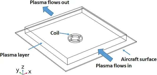
Figure 1.The schematic of the pulsed magnetic field mitigation of the plasma for the three-dimensional model.
(1)The ionization reaction is ignored.This is because the number of electrons produced by the ionization reaction can be ignored relative to the original electron density of the plasma sheath[17].
(2)The electron temperatureTeis constant[1].
(3)The ions are cold in hypersonic flow[13].
(4)The induced magnetic field produced by plasma current is not considered,which means that the magnetic field is produced entirely by the external solenoid.This is understandable since the magnetic Reynolds number is low in the plasma sheath[17].
(5)The velocity of neutral particles remains constant,which is consistent with the initial velocity of plasma flow V.
2.1.Mathematical model formulation
The effect of pulsed magnetic field on plasma density can be described by mass conservation and momentum conservation equations.In order to study the effect of the self-electric field generated by the internal charge of plasma on the electron and ion density distributions,the plasma cannot be assumed to be quasi neutral.Therefore,in the three-dimensional model,electrons and ions are respectively described by fluid equations as follows:
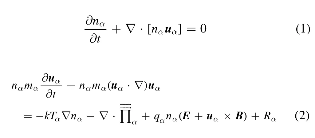
whereα=e,i represent electrons and ions,respectively,nαis the number density of electron and ion,uαis the velocity of electron and ion,mαis the mass of the electron and ion,qαis the electric charge of the electron and ion,kis the Boltzmann constant,is the viscous tensor,Rαis the friction caused by elastic collision,E and B are the electric field and magnetic flux density,respectively.
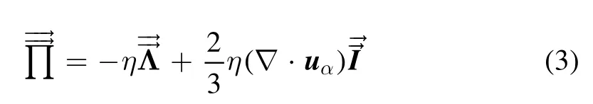
where η is the viscosity coefficient,Making use of the identity:

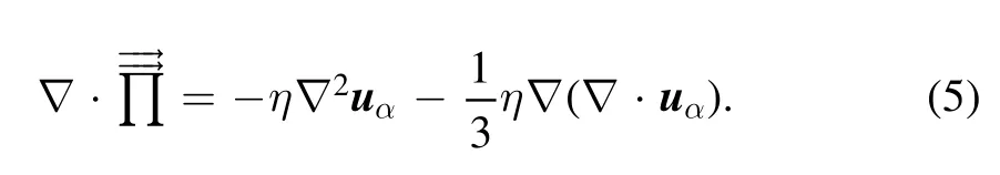
the divergence of viscosity tensorcan be simplified as:
The collision termRαcan be written as:

whereveiis the electron–ion collision frequency,vieis the ion–electron collision frequency,venis the electron–neural collision frequency.Since the collision cross section and frequency between ions and neutral particles are very small in cold plasma,their influence on ion density distribution can be neglected[18].Therefore,in equation(7),the collision term corresponding tovinis ignored.V is the velocity of the neutral particle,which is assumed to be constant.This provides the maximum estimate for the plasma drag force,thus allowing the worst case to accelerate the plasma.
Using equations(5)–(7),the equations(1)and(2)can be rewritten as:

2.2.Electromagnetic field treatment
The spatial and temporal variations of electric field E and magnetic field B are the key factors to determine the plasma density distribution.They are governed by Maxwell’s equations which,in our case,can be written as:
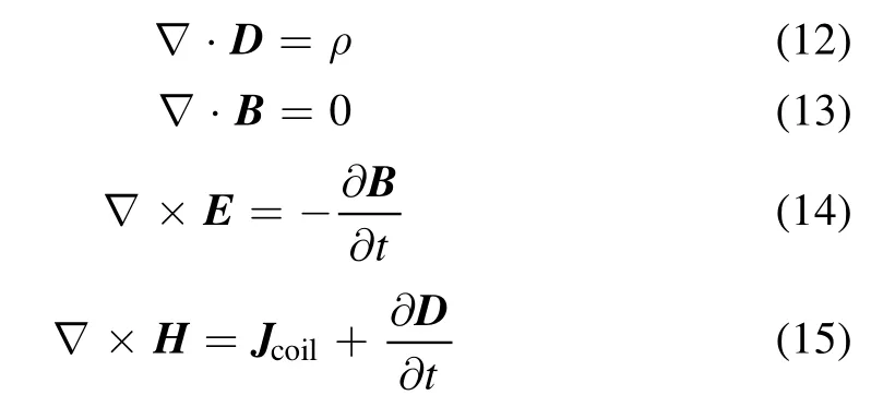
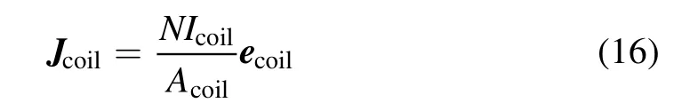
whereNis the coil turns,Icoilis the pulsed current of the coil,Acoilis the cross-sectional area of the coil.
For the convenience of calculation,it is necessary to introduce the magnetic vector potential,A,which is defined by:
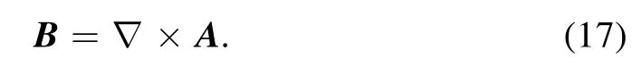
Using expression(17)in equation(14)and introducing the scalar potentialφ,we can obtain:
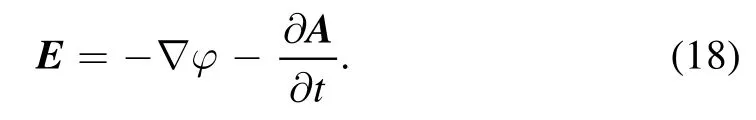
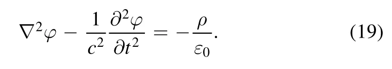
By substituting equation(18)into equation(12)and adopting Lorenz gaugewe can obtain the relationship between the scalar potentialφand the space charge density of the plasma ρ:
Similarly,by substituting equations(17)and(18)into equation(15)and adopting Lorenz gauge,we can obtain the relationship between magnetic vector potential A and current density:
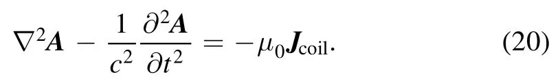
Using equations(19)and(20),we can obtain the magnetic vector potential A and the scalar potentialφ,which means that the electromagnetic E and the magnetic field B can be obtained.
2.3.Numerical method and boundary conditions
The equations(8)–(11)and(17)–(20)are the basic equations to solve the problem of plasma density reduction using pulsed magnetic field.Since the pulsed magnetic field is a time-varying magnetic field,it is a 4-dimensional problem(three coordinates and time).This paper usesCOMSOL Multiphysic?to solve them.The above equations are solved numerically by a timedependent solver inCOMSOL Multiphysic?.To reduce the computational memory,the GMRES algorithm in the solver is selected for numerical solution.Firstly,the initial currentIcoilflowing through the coil is given to calculate the magnetic vector potential A.The initial electron densityneand ion densityniare given to calculate the scalar potentialφ.From A andφ,the distributions of magnetic field B and electric field E are obtained.Then,the B and E are brought into the momentum conservation equation to calculate the Lorentz force term.By solving the electron and ion fluid equations,respectively,the new electron densityneand ion density e obtained.In the next step,the new electron density and ion density are used as the initial state to calculate the new scalar potentialφ,and the new pulse currentIcoilis input to calculate the new magnetic vector potential A.This is repeated until the end of pulse current.
The calculation area is shown in figure 1.The pulsed magnetic field is generated by the electromagnetic coil in the lower part of the plasma layer.The outer part of the plasma layer is the air region.The size of plasma layer is set as 1 m×1 m×0.1 m.The initial velocity of plasma layer is set toV0along the positive direction of they-axis,and the initial density is set toAt the entrance of the plasma layer,the boundary condition is set as the inlet boundary,the entrance velocity isV0,and the plasma density isAt the exit of the plasma layer,the boundary condition is set as the open boundary,which means thatAt the left,right and upper boundary of the plasma layer,the boundary conditions are also set as open boundary.At the lower boundary of the plasma layer,the plasma wall reaction is ignored.Therefore,the boundary condition is set to the wall boundary,which means that
3.Simulation results and analysis
3.1.Initial conditions
According to the data of the RAM-C(Radio-Wave Attenuation Measurement for Study of Communication Blackout)experiment[19],the electron density and the thickness of the plasma layer are different at each altitude.So the initial parameters of plasma layer are set as the typical values at the altitude of 71 km.The electron density distribution at the altitude of 71 km can be obtained from RAM-C[20].
According to the report of National Aeronautics and Space Administration(NASA)[21],the two-Gaussian model can be used to approximate the electron density distribution at the antenna window.So the initial plasma number density distributioncan be represented as two Gaussian distributions and its expressionis as follows:

wherea1anda2represent the gradients of rising and falling electron density,Nepis the peak electron density of the plasma,andzpis the distance between the peak electron density and the aircraft surface.
The peak electron density is in the order ofso the peak electronnumberdensity ofplasmais setasand the thickness of plasma sheath is 0.1 m.The initial plasma number density distributionis shown in figure 2.
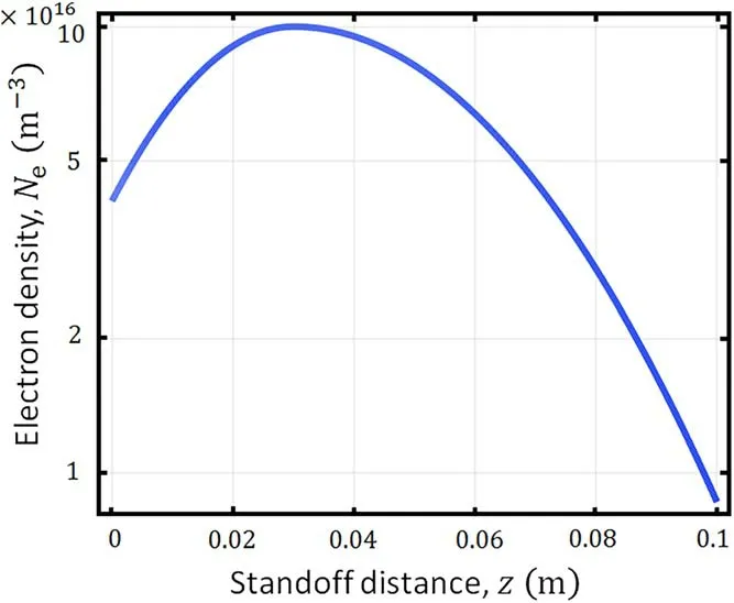
Figure 2.The initial plasma number density distribution.
According to the data of RAM-C[20],the velocity of the plasma flow and the gas temperature vary with the distance from the surface of the aircraft.The attenuation of electromagnetic waves mainly depends on the plasma peak electron density.To simplify the simulation model,the initial velocity and gas temperature at the peak electron density can be used to replace the initial velocity and gas temperature at different distances from the surface of the aircraft.According to[1,13],the velocity of the flow field is usually set at the order of1000 m s-1when considering such problems.According to the data of RAM-C[20],the flow field velocity corresponding to the peak electron density of plasma sheath at the altitude of 70–80 km is2000–3000 m s-1,and the gas temperature is 5000 K.Therefore,the initial velocity and gas temperature here can be set to2000 m s-1and 5000 K.The electron temperature can be assumed constant as 1.5 eV,which is the maximum electron temperature of the RAM-C flight test[13,22].The cold-ion assumption meansso the ion temperatureTican be set as the gas temperature.
The pulsed magnetic field is designed to be generated by a pulse current applied to a coil.The inner diameter of the coil is 12 cm,the outer diameter is 20 cm,the height is 2.4 cm,60 turns.As shown in figure 3(a),the peak value of the pulse current is 2000 A and the pulse width is 500 μs.When the pulsed magnetic field generated by the electromagnet reaches the peak value,the magnetic field distribution along thez-axis direction of the central coil axis is shown in figure 3(b).The magnetic field at the position where the coil adheres to the plasma sheath is the largest,reaching 0.85 T,and gradually attenuates with the increase of distance.The magnetic field at the other end of the plasma layer attenuates to 0.15 T.
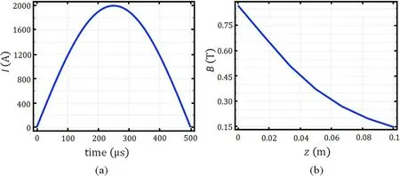
Figure 3.Variation of pulse current and distribution of magnetic field.(a)The pulse current.(b)The magnetic field distribution along the zaxis direction of the central coil axis.(t=250 μs).
3.2.Characteristics of the density distribution in plasma flow field
Under the action of the pulsed magnetic field,when the pulse reaches the peak time(250μs),the electron density distribution of the plasma in thex-yplane at the place where the initial number density is the largest(z=0.03 m)is shown in figure 4(a).The electron density distribution of the plasma in they-zplane at the place wherex=0 m is shown in figure 4(b).The simulation results show that the plasma converges to the center of the electromagnet,and an area of electron number density reduction appears at the back of the electromagnet.This shows that the pulsed magnetic field can indeed reduce the plasma density.
Using the model proposed in[23],the attenuation coefficient of different frequency signals in the plasma layer with different densities can be obtained.As shown in figure 5,the electron densities change from1×1016m-3to 12×1016m-3,and the thickness of plasma layer is set to 0.1 m.The signal attenuation coefficient decreases with the decrease of electron density.When the signal attenuation exceeds 30 dB,the communication blackout problem will appear[24].Therefore,when the initial plasma number density is 1×10¹⁷m-3,L-band signals and part of the S-band signals will enter the ‘blackout’.The density limitation of L-band signals is7.4×1016m-3,which means that the reduction of electron density should be more than 26%.
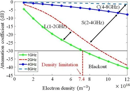
Figure 5.The attenuation coefficient of different frequency signals in the plasma layer with different densities.
In order to obtain the three-dimensional size of the density reduction region,we add the density contours of the plasma in figure 4.As shown in figure 4(a),the diameter of the area with 43% electron density reduction reaches 10– 15 cm,and the area with 26%electron density reduction is much bigger.So the size of the ‘magnetic window’ is far enough for antenna communication.As shown in figure 4(b),the applied pulsed magnetic field can effectively reduce the plasma number density at 10 cm from the surface of the vehicle,where the peak density of plasma is at 3 cm.According to the data of RAM-C flight experiment,the peak density of plasma sheath is about 1– 2 cm away from the aircraft surface[1,25].This means that pulsed magnetic field can effectively alleviate the communication blackout of L-band signal.
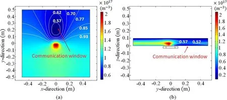
Figure 4.The density distribution of the plasma.(a)The density distribution of the plasma in the x-y plane at the place where the initial number density is the largest(z=0.03 m).(b)The density distribution of the plasma in the y-z plane at the place where x=0 m.
In order to determine the best position of the antenna,we need to find the position with the lowest plasma density.Figure 6 shows the reduction of plasma density at differentzaxis heights from the aircraft surface.As shown in figure 6(a),the area with more than 26% decrease in electron density reaches 0.42 m in they-axis direction.The position where the electron density decreases most isy=0.2 m,which is 8 cm away from the back of the electromagnet(y=0.12 m).The distribution of electron density along thex-axis direction aty=0.2 m is shown in figure 6(b).The electron density reaches the lowest atx=0 m,and the area with more than 26% decrease in electron density reaches 0.3 m in thex-axis direction.So the best place for antenna is at the position(y=0.2 m,x=0 m).
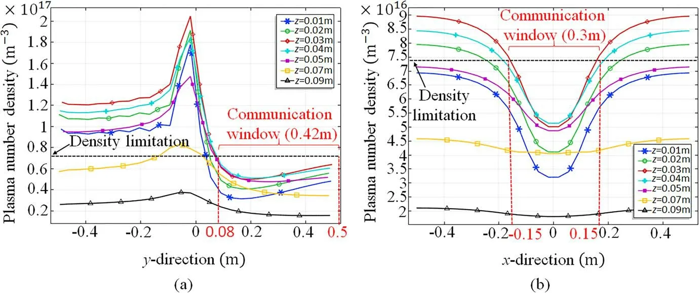
Figure 6.The reduction of plasma density at different z-axis heights from the aircraft surface.(a)The distribution of electron density at different z-axis heights along the y-axis direction(t=250 μs,x=0 m).(b)The distribution of electron density at different z-axis heights along the x-axis direction(t=250 μs,y=0.2 m).
The rationality of the simulation results in figures 4 and 6 can be explained by theoretical analysis.Neglecting the effect of viscous termsand collisions between electrons and ions.Considering the situation that the plasma reaches a stable state,the momentum termcan be ignored.The momentum conservation equation(2)can be written as:

Suppose that the magnetic field has onlyz-direction componentBz,then the equation(22)can be simplified to two-dimensional case:
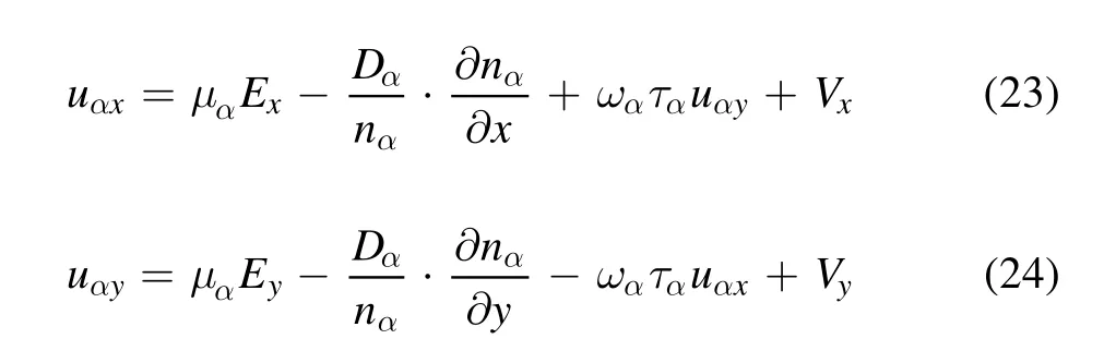
With the equations(23)and(24),the particle velocityon thex-yplane can be written as:
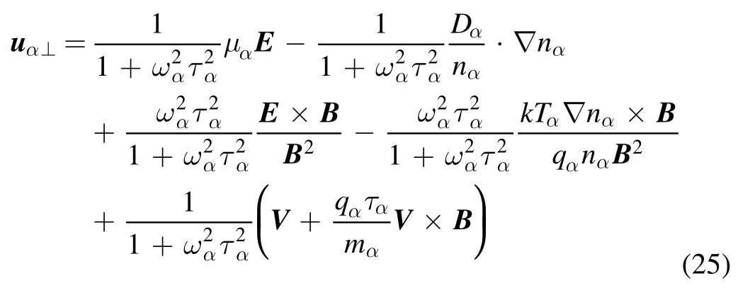
The distributions of magnetic field and induced electric field are shown in figure 7.The red arrows in figure 7(a)and the white arrows in figure 7(b)indicate the directions of the magnetic field and the electric field respectively.According to the distributions of pulsed magnetic field and induced electric field,the directions of the drift terms can be obtained.The diffusion under particle pressureuα?nand the diamagnetic diffusionuα?n×Bare mainly caused by the density gradient?n.The density gradient is caused by the drift terms,so we only need to analyze the drift termandAs shown in figure 7(b),in the region near the point(x=0 m,y=0.1 m),where E×B field plays a major role,the directions of the drift termsαuEanduαV×Bare perpendicular to they-axis,only the directions of the drift termsuαE×BandαuVare parallel to they-axis.Since the plasma flow field is along they-axis,the drift along they-axis plays an important role in the plasma velocity,which means that the decrease of plasma density is mainly determined by drift termsuαE×BanduαV.The directions of these two drift terms are opposite in the region near the point(x=0 m,y=0.1 m),so it is necessary to analyze the magnitude of them.
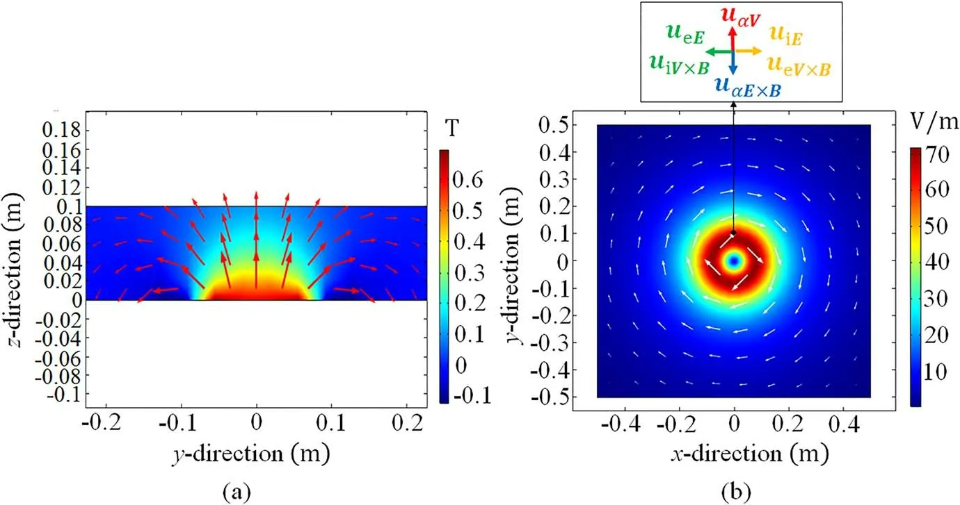
Figure 7.The distribution of the electromagnetic field.(a)Distribution of the magnetic field in y-z plane(t=125 μs,x=0 m).(b)Distribution of induced electric field and directions of the drift terms in the x-y plane(t=125 μs,z=0.03 m).
Figure 8 shows the velocities of the drift termsuαE×BanduαVon they-axis(x=0 m,z=0.03 m).The time corresponding to these data is a typical value in the middle of the pulse rise phase(t=125μs).The positive values of drift velocities indicate that the velocity direction is along the positive direction ofy-axis.The two driftsueE×BanduiE×Bhave the same change tendency along theydirection.The driftsueVanduiVhave the same change tendency too.This is because these drifts are independent of the charge carried by the particle.The drift velocities of electron are higher than that of ion,this is because the mass of ions is larger than that of electrons.
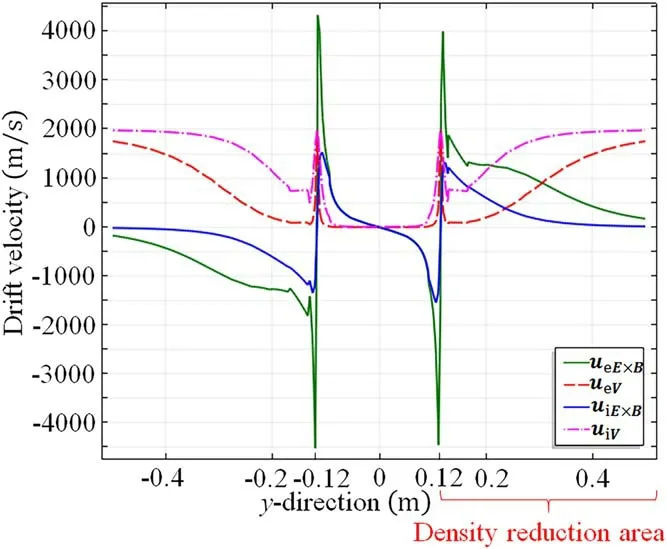
Figure 8.The velocities of the drift terms uα E×B and uαV on the yaxis(t=125 μs,x=0 m,z=0.03 m).
In they-axis range of-0.5 m to-0.12 m,the E×B drift velocityuαE×Bincreases gradually,and theαuVdecreases gradually as shown in the figure 8.This is because the increasing magnetic field leads to the increase ofαG2and decrease ofαG.1Since the direction of the drift termuαE×Bpoints to the negative direction of they-axis,which is opposite to the direction of the flow field,the increase ofuαE×Bleads to the gradual decrease of the flow field velocity.The decrease of flow field velocity means that the plasma entering from the inlet keeps staying in this range,which leads to the increase of plasma density in this range.This is why the plasma density is higher than the initial density in this range(y=-0.15 m to -0.12 m)as shown in fgiures 4(b)and 6(a).In they-axis range of-0.12 m to0.12 m,the E×B driftpoints to the center of the electromagnet(y=0 m)as shown in the figure 8.This is why the plasma density increases sharply at the center of the electromagnet.The direction of E×B drift mutates aty=-0.12 m andy=0.12 m.This is because the magnetic field changes direction there.In theyaxis range of0.12 m to0.5 m,both the E×B drift velocityand theuαVpoint to the positive direction of they-axis,which means that the plasma flows out of this region rapidly.Therefore,the plasma density in this region decreases.The plasma at the front of the positiony=0.12 m converges at the center of the electromagnet,while the plasma at the back of this position flows out rapidly.This is the reason why the plasma density decreases rapidly near the positiony=0.12 m.
3.3.Characteristics of the density time evolution in plasma flow field
Figure 9 shows the time evolution of plasma density under the pulsed magnetic field(0 – 500μs).The first contour map in they-xplane,which is taken prior to the current pulse,shows that the plasma is uniform in thex-yplane.As the pulse increases(0– 250μs),the plasma begins to converge to the center of the coil,and a region of reduced electron density appears at the back of the coil.This is because the E×B drift direction points to the center of the coil at this stage.When the pulsed magnetic field reaches the peak value(250μs),the induced electric field begins to change direction,which means that the E×B drift also changes direction.However,the plasma density at the center of the coil continues to increase,and the density at the back of the coil also continues to decrease.The increase of density in the center of the coil does not stop untilt=375μs.In addition,figure 10 shows the time evolution of electron density at the location(y=0.2 m,x=0 m),which is the most suitable location for antenna placement.We found that the electron density of this position also continued to decrease after the peak of the pulse.These phenomena should be caused by magnetic confinement.
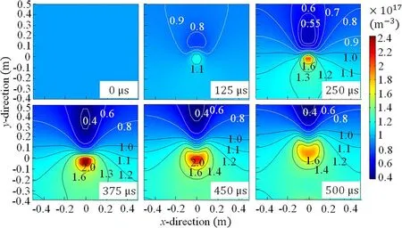
Figure 9.Time evolution of the plasma density in the x-y plane(z=0.03 m).
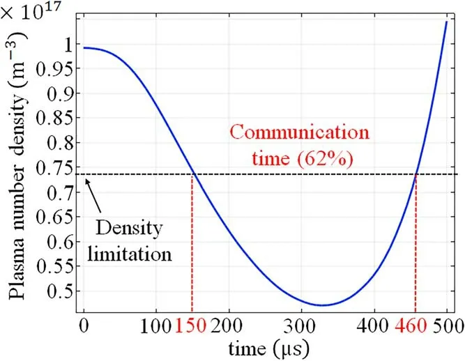
Figure 10.The time evolution of electron density at the location(y=0.2 m,x=0 m,z=0.03 m).
In order to explain this phenomenon,on thex-ysection(z=0.03 m)shown in figure 9,we select two typical positions along they-axis,y=0.1 m andy=0.2 m.These two points are located on both sides of the rear edge of the coil(y=0.12 m),which means that the magnetic field directions of these two points are opposite.We calculate theuαE×Bdrift term and theαuVdrift term of these two points respectively,as shown in figure 11(a).The positive value in figure 11 indicates that the drift direction is along the positive direction of they-axis,while the negative value is opposite.Because the mass of ions is much larger than that of electrons,a more representative ion drift term is selected for analysis.From figure 11(a),we can see that in the pulse descending phase(2 50– 400μs),due to the change of the induced electric field direction,theuiE×Bdrift begins to point to the positive direction of they-axis at the position ofy=0.1 m.At this time,theuiVdrift also points to the positive direction of theyaxis.However,since the magnetic field is very large at this stage,theuiVdrift velocity is at the minimum under the magnetic constraint.At the same time,due to the slow change of the magnetic field,the induced electric field is at the minimum,which means that theuiE×Bdrift is also at the minimum in this stage.Therefore,we can get the sum of these two drift velocities,as shown in figure 11(b).Although theui+is along the positive direction ofy-axis,it is still less than the velocity of the front entrance(2000 m s-1).This means that the plasma flowing into this region(y=0.1 m)from the front entrance will still be decelerated and trapped in this region.So the plasma density in this region continues to increase.In addition,as shown in figure 11(b),beforet=300μs,theui+aty=0.2 m is greater than that aty=0.1 m,which means that the plasma aty=0.2 m flows out faster than that aty=0.1 m.Therefore,in figure 10,beforet=300μs,the plasma density still decreases.This shows that magnetic confinement begins to work in the peak phase,although the E×B drift no longer works.That is why the plasma density continues to decrease.
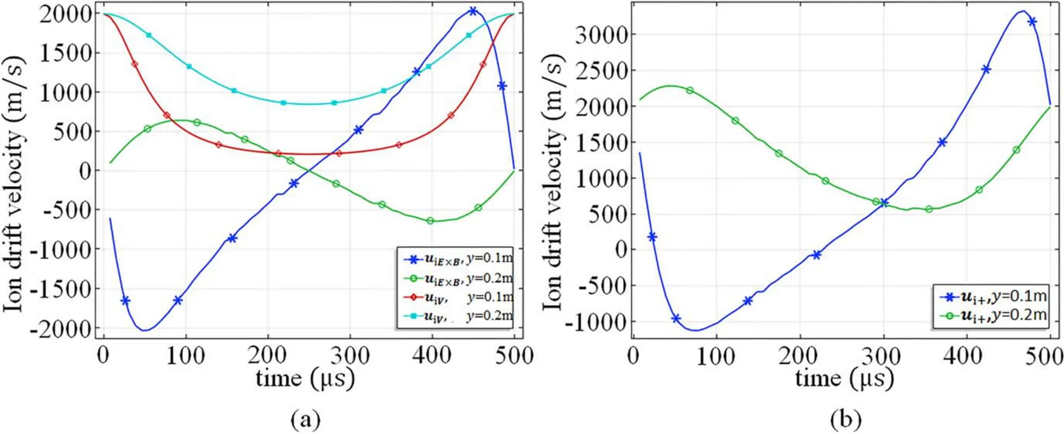
Figure 11.Ion drift velocity(x=0 m,z=0.03 m).(a)TheuiE×Bdrift term and the ui Vdrift term at the position y=0.1 m and y=0.2 m.(b)The ion drift velocityui+at the position y=0.1 m and y=0.2 m.(ui+=uiE×B+ui V).
Aftert=300μs,theui+aty=0.1 m is larger than that aty=0.2 m,which means that the plasma flows in from the front end faster than it flows out fromy=0.2 m.So the plasma density in figure 10 begins to increase.Aftert=400μs,theui+aty=0.1 m is larger than that at the front entrance(2000 m s-1),which means that the magnetic confinement no longer works.Therefore,as shown in figure 9,aftert=400μs,the high density region in the center of the coil begins to move in the positive direction of they-axis with the flow field,and accordingly,the density reduction region also begins to move in the positive direction of they-axis.
Based on the above analysis,the simulation results of figures 9 and 10 can be explained physically.Under the action of pulsed magnetic field,the plasma is first affected by a strong induced electric field and a gradually increasing magnetic field.The magnetic field is mainly along thez-axis,while the induced electric field is mainly in thex-yplane.Therefore,the induced electric field and magnetic field form an orthogonal E×B field,whose direction refers to the central axis of the coil.Under the action of E×B field,electrons and ions will drift in the same direction as E×B field,which is called E×B drift.The E×B drift direction at the back of the coil is opposite to that of the flow field,so the plasma in the region of the induced electric field will move towards the center of the coil,while the plasma outside the region will continue to move backward along the flow field.This results in a region of reduced plasma density at the back of the coil.With the increase of magnetic field,the induced electric field will gradually decrease.When the magnetic field increases to the peak value,the induced electric field will almost decay to zero.At this time,E×B drift no longer works.But,the electron density continues to decrease.This is because with the increase of the magnetic field,the confinement effect of the magnetic field on the plasma gradually increases.When the plasma flows through the center of the coil,it will be constrained by a strong magnetic field,which will also reduce the plasma density at the back of the coil.After the pulse reaches its peak,as the magnetic field decreases to a small value,the magnetic field will not be enough to constrain the high-density plasma in the center of the coil.At the same time,with the reverse increase of the induced electric field,E×B drift begins to take effect again.However,due to the change of the electric field direction,the direction of E×B drift at the back of the coil is consistent with the flow field.So,the high-density plasma at the center of the coil will accelerate to flow backward under the effect of E×B drift.This is the reason why the high density region in figure 9 moves to the positive direction of they-axis and the plasma density in figure 10 recovers rapidly.The simulation results are reasonably explained by the above physical analysis,which proves the accuracy of the simulation model to a certain extent.
It can be seen from figure 10 that at the back of the electromagnet,the maximum reduction of electron density can reach 65% within a pulse duration.The time when the electron density is below the critical communication density accounts for more than 62%of the pulse duration.If multiple pulses are used continuously,intermittent communication may be realized during the ‘blackout’.For GPS navigation signals,there is only190μs‘blackout’time per500μs.Since the typical flight speed of a hypersonic vehicle is from 1000 m s-1to7000 m s-1[20],the flight distance is less than 1.3 m during the190μs signal ‘blackout’ time.This should improve the accuracy of navigation and positioning.
When the initial velocity of the flow field is low,the spatial distribution and temporal evolution of plasma density will be different.The simulation results when the initial velocity of flow field is set asV=200 m s-1are shown in figure 12.From the electron density distribution at the time of pulse peak in figure 12(a),it can be found that when the flow velocity is low,a ring-shaped plasma density reduction region will be formed around the magnetic field.At the back of the coil,the decrease of density is relatively large,and the shape is crescent.This is because the distance of plasma flow in the pulse duration is smaller than the coil size at low flow velocity.As a result,only a small part of the plasma at the back of the coil flows out when the magnetic confinement is applied.Therefore,magnetic confinement no longer has the effect of density reduction,that is,the influence of flow field on plasma density becomes smaller.In this case,the E×B drift is the main reason for density reduction.Since the E×B drift points to the center of the coil,the plasma around the coil moves to the center of the coil,resulting in a ring-shaped density reduction region around the coil.This is also the reason why the plasma density in figure 12(b)reaches the lowest value at the time of peak pulse(t=250μs)and then recovers.Due to the lack of the effect of magnetic confinement on density reduction,the decrease range of plasma density is smaller than that of high velocity.In addition,the communication time is reduced to200μs,which accounts for 40% of the pulse duration.Therefore,for the case of low velocity,the required magnetic field needs to be increased.
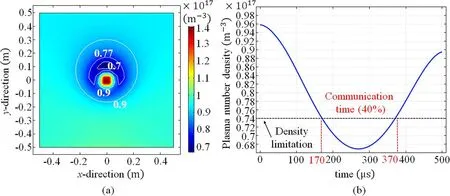
Figure 12.The density reduction of the low flow velocity case(V=200 m s- 1).(a)The density distribution of the plasma in the x-y plane at the place where the initial number density is the largest(z=0.03 m).(b)The time evolution of electron density at the location(y=0.1 m,x=0 m,z=0.03 m).
3.4.Effects of the self-electric field in plasma flow field
Figure 13 shows the velocities of the drift termsαuEandon they-axis(x=0 m,z=0.03 m).The time corresponding to these data is a typical value in the middle of the pulse rise phase(t=125μs).The positive values of drift velocities indicate that the velocity direction is along the positive direction ofx-axis.It can be seen from the figure 13 that the drift terms of electrons and ions are in opposite directions.Especially at the edge of the coil(y=±0.12 m),the drift termsαuEof electrons and ions are not only in opposite directions,but also have larger drift velocity.This indicates that electrons and ions will move in opposite directions at this position.In addition,we have obtained the velocity distribution of electrons and ions att=125μs,as shown in figure 14.The white arrow in figure 14 represents the direction of the velocity.As shown in figure 14,the velocities of electrons and ions in the center of the coil reach the lowest,which is caused by E×B drift and magnetic confinement.But at the back of the coil,the velocity of the electrons deflects to the left and the velocity of the ions deflects to the right.In addition,on the left side of the coil,due to the effect of the induced electric field,the electron speed is slow,while the ion speed is just the opposite.So electrons should be denser on the left side of the coil,while ions should be denser on the right side.However,according to our simulation results,the density distributions of electrons and ions are almost the same.This is caused by the selfelectric fieldEselfin the plasma.
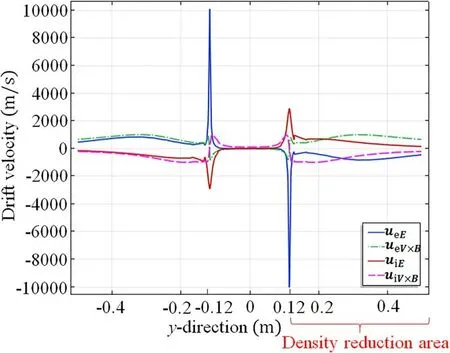
Figure 13.The velocities of the drift terms uαE and uα V×B on the yaxis(t=125 μs,x=0 m,z=0.03 m).
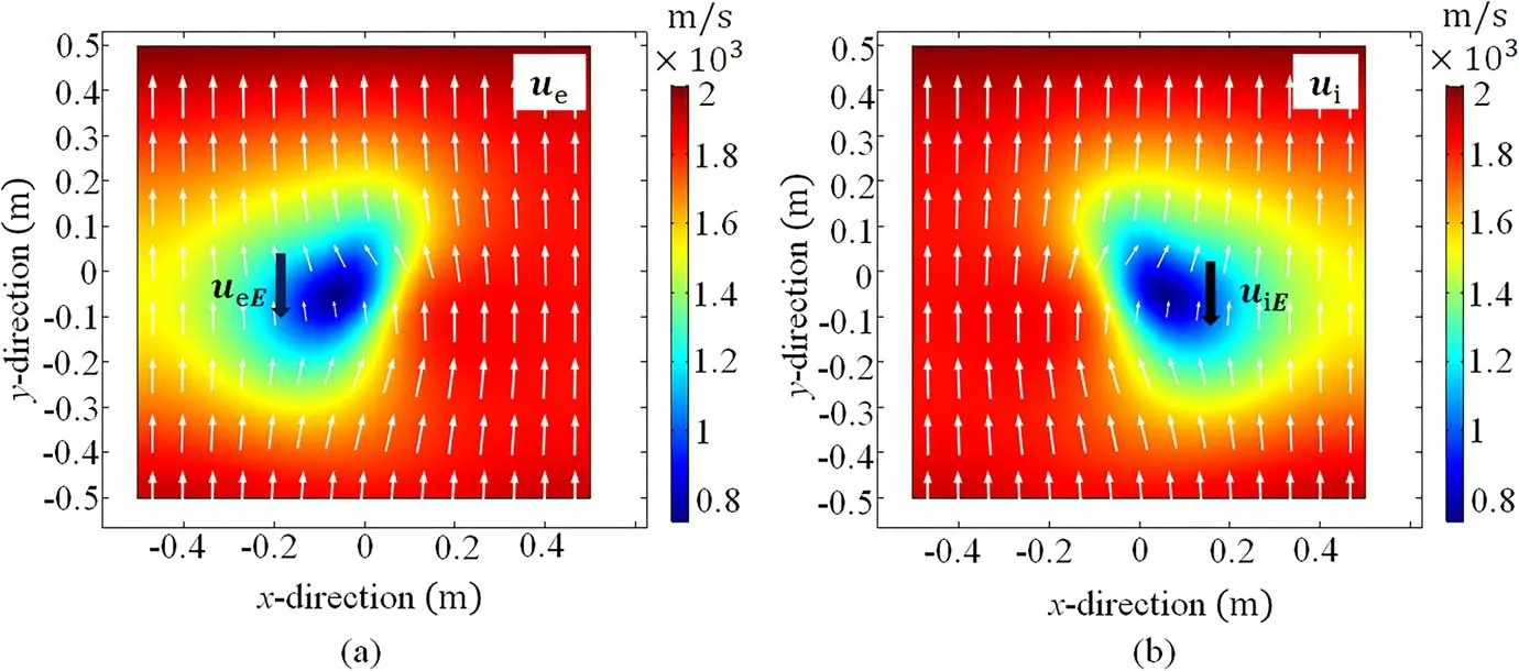
Figure 14.Distribution of electron velocity ue and ion velocity ui in x-y plane(t=125 μs,z=0.03 m).(a)Distribution of electron velocity ue .(b)Distribution of ion velocity ui.
According to equation(18),the electric field E in equations(9)and(11)mainly consists of two parts.One part is the induced electric field produced by the pulsed magnetic field,which is obtained from the current densityin equation(20).The E×B drift is mainly caused by the induced electric fieldThe other part is the self-electric field generated by the space charge in the plasma,which is obtained from the space charge density of the plasmaρin equation(19).The selfelectric fieldis the key factor to keep the plasma quasi neutral.Figure 15 shows the potential distribution in thex-yplane(z=0.03 m).Since the electrons and ions accumulate at the positions where their velocities decrease respectively,they will separate and produce a self-electric fieldas shown in figure 15.Under the action of the self-electric field,the ions and electrons on both sides will converge to the center of the electromagnet to keep the electric neutral.Therefore,after a short charge separation,the density distribution of electrons and ions will remain the same.
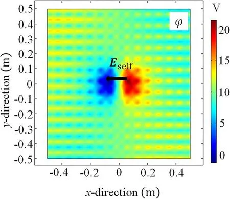
Figure 15.The potential distribution in the x-y plane(t=125 μs,z=0.03 m).
Based on the above analysis,the simulation results of figures 13–15 can be explained physically.During the action of pulsed magnetic field,an annular induced electric field will be produced.Electrons and ions in the action area of the induced electric field will be subjected to the electric field force in the opposite direction.This is the reason for the opposite direction of the electron and ion drift termαuEin figure 13.When the plasma flow field passes through the induced electric field region,the electron flow field is subjected to the electric field force in the counter-clockwise direction,while the ion flow field is subjected to the electric field force in the clockwise direction.Therefore,in figure 14,the electron flow field has a left-handed shift in the induced electric field region,while the ion flow field has a righthanded shift.On the left side of the coil,the induced electric field is along the positive direction of they-axis,so the electrons are slowed down by the electric field force along the negative direction of they-axis and accumulated.Similarly,on the right side of the coil,the induced electric field is in the negative direction ofy-axis,so the ions are slowed down by the electric field force in the negative direction ofy-axis and accumulated.This causes the potential on the right side of the coil to be higher than that on the left side,forming a charge electric fieldEselfpointing to the left side,as shown in figure 15.Under the action of this charge electric field,which is called self-electric field here,the electrons and ions will move towards the center,thus maintaining the quasi neutrality of the plasma dynamically.
4.Discussion
In the simulation model proposed in this paper,it is not assumed that the plasma is quasi neutral,although this is a common assumption in this kind of problem.The density distributions of electrons and ions are simulated by fluid equations,respectively.According to the simulation results,we found that the density distributions of electrons and ions are almost the same.We have analyzed it and thought that it is caused by the self-electric field of plasma.However,it is not appropriate to assume that the plasma is quasi neutral,because the quasi neutral hypothesis means that the electron density and ion density are expressed by the same variablen=ne=ni,which means that the plasma self-electric fieldEselfis zero.According to figure 15,the magnitude of selfelectric fieldEselfis close to that of induced electric fieldEapply,which means that the existence ofEselfwill also affect the E×B drift.The direction ofEselfpoints to the negative direction of thex-axis,which means that the direction ofEself×Bpoints to the positive direction of they-axis.This is opposite to theEapply×Bdrift caused by the induced electric field at the back of the coil,which means that the effect of the pulsed magnetic field will be weakened.Therefore,the effect of self-electric fieldEselfcannot be ignored.If the plasma is regarded as quasi neutral,the simulation results should be better than the actual situation.
The influence of flow field is considered in our model.The density distribution of plasma flow field in pulsed magnetic field is different from the case that the plasma is at rest.When the plasma is at rest in the initial stage,which is the case in some experiments[16],there will be noαuVdrift anduαV×Bdrift in the plasma.Therefore,electrons and ions only converge to the center of the coil due to E×B drift.Since the induced electric fieldEapplyis annular,the E×B drift direction will point to the center of the coil.Therefore,an annular region with reduced plasma density will be formed at the outer edge of the coil,which is different from the case that flow field exists.Since the E×B drift directions of electrons and ions are the same,there is no significant self-electric fieldEself.In this case,the quasi neutral assumption of plasma is reasonable,which means that the model will be much simpler.In addition,since there is noαuVdrift in the plasma,the magnetic confinement can only keep the plasma density unchanged,but will not make it continue to decrease.This means that when the pulsed magnetic field reaches the peak value,the plasma density will not continue to decrease as shown in figure 10.For the above reasons,when we reduce the flow velocity to200 m s-1,as shown in figure 12(a),the density reduction area has both the ring area corresponding to the static state and the crescent area at the back of the coil corresponding to the high velocity state.In addition,the decrease of electron density at low flow velocity is smaller than that at high flow velocity,as shown in figure 12(b).Therefore,when we are talking about the plasma sheaths that produced by hypersonic vehicles,the influence of flow field cannot be ignored.
Compared with DC magnetic field,the advantage of using pulsed magnetic field to reduce plasma density is that the required magnetic field is smaller.This is because the pulsed magnetic field has the combined effect of E×B drift and magnetic confinement.The disadvantage of pulsed magnetic field method is that the pulse duration is short.If continuous pulsed magnetic field can be generated,intermittent communication may be realized,which is worthy of further study.
5.Conclusions
In this paper,we propose a three-dimensional model for plasma sheath density reduction using pulsed magnetic field.The plasma is regarded as a flow field with initial velocity V in this model.Ions and electrons are solved by independent fluid equations and coupled by plasma self-electric fieldEself.Taking the typical parameters of plasma sheath at the height of 71 km as an example,the distribution characteristics and time evolution characteristics of plasma density in the flow field,as well as the effect of self-electric fieldEselfon the distribution of plasma density,are studied and physically analyzed.The simulation results indicate that under the combined action of the pulsed magnetic field and the plasma flow field,a region with reduced electron density will be formed at the back of the electromagnetic coil.The results of three-dimensional plasma density distribution show that the effective size of the plasma density reduction region can reach 0.3 m×0.4 m..The most suitable position for the antenna is at the back of the coil,where is 0.2 m away from the coil center.The time evolution of plasma density shows that the effective density reduction time can reach 62% of the pulse duration,and the maximum reduction of plasma density can reach 55%.
In addition,the effects of self-electric field and flow field are discussed.According to the simulation results,we found that the plasma self-electric field is the main factor to keep the electron and ion density distribution consistent.However,the quasi neutral assumption of plasma in the flow field is not appropriate,because the self-electric field of plasma will weaken the effect of the pulsed magnetic field on the reduction of electron density,which cannot be ignored.Meanwhile,we found that the flow field has an important influence on the shape,size and time evolution of the plasma density reduction region.When we are talking about the plasma sheaths that are produced by hypersonic vehicles,the influence of the flow field cannot be ignored.The calculation results could provide useful information for the communication blackout mitigation.
Acknowledgments
This work is supported by the Innovation Fund for TT&C and Measurement of Near Space Vehicles(No.20180102).
ORCID iDs
猜你喜歡
Plasma Science and Technology(2022年8期)2022-09-14 08:18:12
Plasma Science and Technology(2022年7期)2022-08-01 11:34:50
Plasma Science and Technology(2022年3期)2022-04-15 05:13:00
Plasma Science and Technology(2021年9期)2021-09-10 09:26:40
少先隊(duì)活動(dòng)(2020年8期)2020-12-18 02:32:07
少先隊(duì)活動(dòng)(2020年7期)2020-12-18 01:48:39
少先隊(duì)活動(dòng)(2020年7期)2020-08-14 01:18:08
西部論叢(2019年8期)2019-03-08 03:17:08
小天使·一年級(jí)語(yǔ)數(shù)英綜合(2019年11期)2019-01-13 01:31:29
心理與健康(2017年1期)2017-05-30 11:03:38
 Plasma Science and Technology2021年7期
- Plasma Science and Technology的其它文章
- Numerical simulation of carbon arc discharge for graphene synthesis without catalyst
- Enhanced removal of ultrafine particles from kerosene combustion using a dielectric barrier discharge reactor packed with porous alumina balls
- Visualization of gold nanoparticles formation in DC plasma-liquid systems
- Rice plant growth and yield:foliar application of plasma activated water
- An active tunable Fano switch in a plasmafilled superlattice array
- Comparison of sample temperature effect on femtosecond and nanosecond laser-induced breakdown spectroscopy