
Review: Research Progress for Electric Vehicle Hub Motor Driving Technology
2020-07-16 08:43:16JunqiuLiJiweiLiuChaoSunandFengchunSun
Junqiu Li, Jiwei Liu, Chao Sun and Fengchun Sun
(State Engineering Laboratory of Electric Vehicles, Beijing Institute of Technology, Beijing 100081, China)
Abstract: Due to high efficiency, high controllability, high integration, lightweight, and other advantages, electric vehicle with hub motor driving technology has become an emerging trend of chassis technology. This paper concludes the current state-of-the-art of hub motor drive technologies. Firstly, it summarizes recent hub motor drive products and makes suggestions for hub motor drive schemes in different application scenarios. Then research on hub motor drive key technologies such as integrated design, thermal optimization, lightweight, and intensity optimization is investigated. Considering the high response accuracy and zero delay characteristic of hub motor driving system combined with advanced distributed dynamics control technology that can further improve vehicle performance, this paper also analyzes existing chassis dynamics control technologies of hub motor driving system. Considering the development trend of vehicle electrification, intelligentization, network connection, and current research, this paper makes some forecasts for hub motor drive technologies development in the conclusion.
Keywords: hub motor drive; current research; integrated optimization technique; control technology; development direction
1 Introduction
Compared with traditional vehicle chassis, electric vehicle with hub motor driving technology removes mechanical transmission components such as half shaft to improve the transmission efficiency. It raises power density and is conducive to the whole vehicle lightweight and optimal placement of the chassis, having unique advantages in economy performance, power output, and ride performance. Its high response accuracy and almost zero hysteresis characteristics make it superior in realizing distributed electronic differential and torque coordinated control to meet the needs of power. In addition, the integration with steering system and suspension system promotes the trend of high integration and modularization of chassis. Combined with steer-by-wire technology, hub motor driving technology obtains better chassis dynamics characteristics and handling performance. However, increasing unsprung mass and poor thermal conditions makes it necessary to optimize key components. Meanwhile, it is important and difficult to construct a multi-input-output coupling chassis dynamics control method due to high nonlinear and high dynamics characteristics of hub motor driving technology.
In this paper, recent progress of hub motor driving technology research is introduced. The paper is organized as follows: a summary of hub motor products and suggestions on technical driving schemes are provided in Section 2; Section 3 illustrates integrated optimization technology of hub motor driving system; the chassis dynamics control strategies for distributed vehicle with hub motor are analyzed in Section 4; and the future development prospects of hub motor driving technology are proposed in Section 5.
2 Development Status and Technical Scheme of Hub Motor Driving System
2.1 Development Status of Hub Motor Drive
There are two typical topologies of hub motor drive: hub motor direct drive construction (Fig.1(a)[1]) and hub motor deceleration drive construction (Fig.1(b)[1]). The former includes a low-speed outer rotor hub motor, which directly drives the vehicle, and its outer rotor and rim are integrated as rotating parts to realize wheel rotation. The wheel is connected by the stator shaft and the kingpin. Appling this construction obtains wide speed range, short transmission chain, quick dynamics response, and high transmission efficiency, but high motor cost appears and the permanent magnet fails easily under high torque condition. The latter includes a high-speed inner rotor hub motor, which outputs torque through the fixed speed ratio reducer to achieve wheel drive. Appling the latter construction obtains wide torque range, high torque density, high dynamics performance, but issues such as hub space limitation and increasing unsprung mass exist.
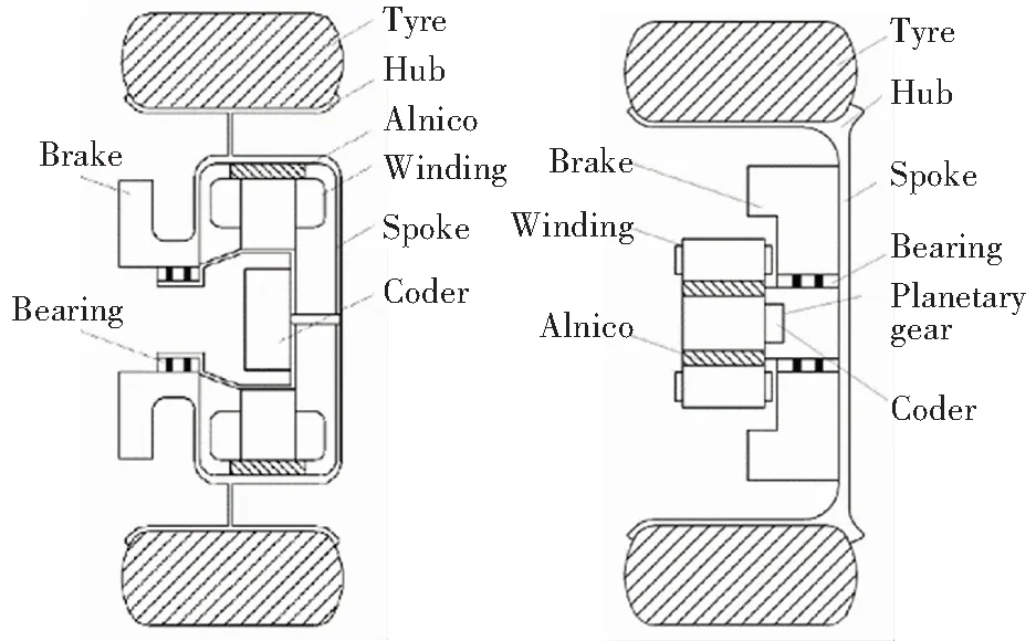
(a) Hub motor direct drive construction (b) Hub motor deceleration drive construction
Fig.1 Hub motor drive construction(Reprinted with permission from Ref.[1].Copyright 2016, Inderscience)
Great progress has been made in hub motor driving system for passenger vehicles abroad. In 2013, based on the Ford fiesta, Ford and Schaeffler cooperated in developing the E-wheel Drive, which adopts water-cooled Schaeffler inner rotor hub motor with reducer (Fig.2(a)). In 2019, Protean launched a new conceptual product named Protean360+, which adopts outer rotor hub motor direct drive construction (Fig.2(b)). It integrates suspension system, steering system, and hub motor, and achieves 360-degrees rotation, enabling the vehicle to successfully turn and park in a narrow space. With the vigorous promotion of new energy automobile industry and related technologies in China, the development of hub motor system has increased rapidly in recent years. Many companies have cooperated with foreign manufacturers to promote distributed automobile industry. To produce hub motors and electric wheel used in passenger vehicles, Zhejiang Asia-Pacific Mechanical & Electronic Co., Ltd. cooperated with Elaphe Propulsion Co., Ltd., and Zhejiang Vie Science and Technology Co., Ltd. cooperated with Protean Electric Co., Ltd.
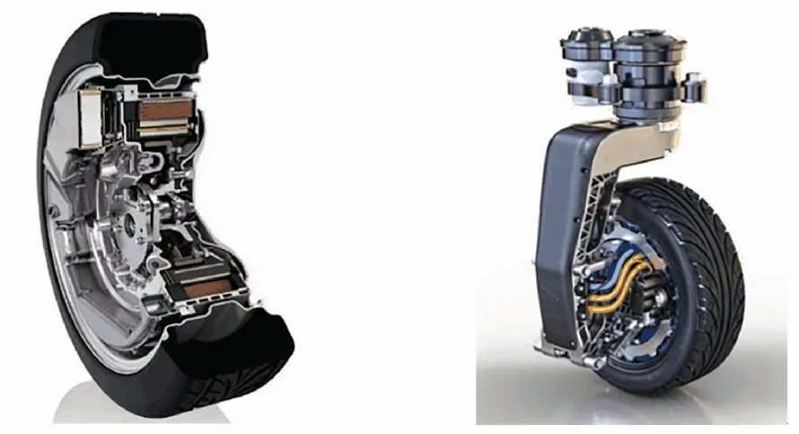
(a)Schaeffler hub motor driving (b) Protean360+ hub motor
system driving system
Fig.2Hubmotordrivingsysteminpassengervehicles
Hub motor driving system can meet the needs of power, handling, and stability of commercial vehicles[2]. The Dutch electric bus "vdlciteaslf-120" assembles the ZF AVE130 wheel-side electric drive axle ( Fig.3 (a)). It adopts the water-cooled high-speed inner rotor motor deceleration drive construction, where the disc brake is integrated between motor and hub, and the left and right electric drive units are connected by a rigid axle. The Dutch E-Traction motor driving system integrates low-speed outer rotor motor and disc brake in the hub (Fig.3 (b)). It adopts hub motor direct drive construction, achieving short transmission chain and high transmission efficiency, and had been widely used in European commercial vehicles. In China, BYD has developed a commercial wheel-side driving technology (Fig.3 (c)). The torque output from the motor is increased by the multi-stage deceleration of the reducer. The technology was applied to BYD K9 series of electric buses in 2010. Zhengzhou Yutong Bus Co., Ltd. has developed an efficient distributed electric bus with independent suspension system, which integrated efficient high speed motor, reducer, and independent suspension.
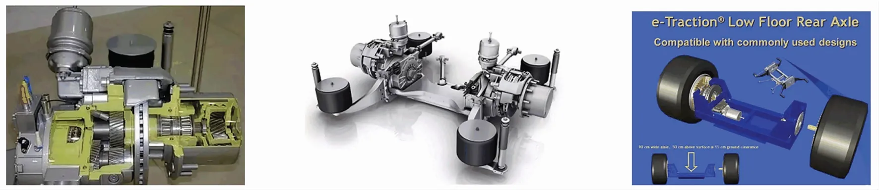
(a)ZF electric drive rigid axle (b)E-Traction electric drive axle (c)BYD wheel-side driving system
Many countries have conducted research on hub motor driving technology in military special vehicles and developed a variety of combat vehicles. German magnetoelectric motor company launched a hub motor, where stator adopts centralized winding, and stator core and armature winding adopts air-cooling. Its axial length is short, and the power density and torque density are 4-10 times that of the same sized traditional motor. By far it has been applied to different military vehicles. Defence Advanced Research Projects Agency cooperated with Office of Naval Research in RST-V T program, using Hummer and ground motor vehicle (GMV) as benchmarks. The mobility, stealth, and stationary and moving firing accuracy of the RST-V equipped with MM's electric drive wheels (Fig.4 (a)) has at least been doubled. Armscor of South Africa cooperated with BAE to develop the "Big Lynx" 8 × 8 wheeled hybrid vehicle. It selected MM's M68/0 hub motor (Fig.4 (b)) and adopted high-speed inner rotor hub motor deceleration drive construction.
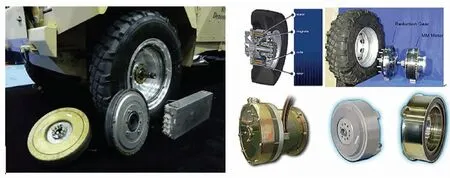
(a) RST-V electric drive wheels (b) MM electric drive wheels
2.2 Analysis of Hub Motor Technical Driving Scheme
Based on the analysis of hub motor driving technology status at home and abroad, the comparison of typical schemes and parameters is summarized in Table 1.
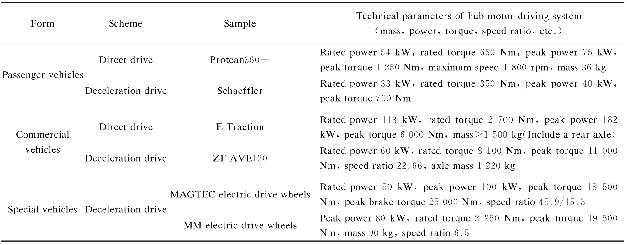
Table 1 Comparison of typical schemes and parameters of hub motor drive
As the main market demand of hub motor driving system in the future, the new energy passenger vehicles are supposed to adopt the outer rotor hub motor direct drive construction, which integrates the motor and brake into the wheel and removes the reducer. This construction with simple structure is beneficial to the whole vehicle lightweight, high transmission efficiency, and economy improvement. There are also applications of the inner rotor hub motor with reduction drive construction which has higher power density.
At present, commercial vehicles mostly adopt two constructions: wheel-side motor axle and outer rotor hub electric axle. The former removes the rotating shaft and differential, releasing the chassis space. It also improves the transmission efficiency. The latter highly integrates the motor, the hub, and the axle, where the motor directly drives the wheel. This construction has more compact structure, less transmission chain, and higher efficiency, making it a development direction of commercial vehicles.
The special vehicles generally adopt the inner rotor hub motor deceleration drive construction. This scheme has higher torque density and more compact structure, which can meet its higher requirements for bearing, driving and braking compared with other vehicles. Although there is no mass production of electric wheel for special vehicles, it has been applied in engineering machinery.The public military test sample vehicles adopt the inner rotor hub motor deceleration drive construction, which can reduce the vehicle weight and meet the vehicle torque demand.
3 Integration Optimization Technology of Hub Motor Driving System
3.1 Structural Integration Technology
In order to reduce the unsprung mass and increase the hub space utilization, it is necessary to integrate the structure of the hub motor driving system. At present, research mainly includes integration of the hub motor and the brake[3], integration of the electromotor shell and the suspension[4], integration of the motor mounting structure and the vibration damping structure[5], integration of the reducer and the hub[6], integration of the steering and braking system[7], etc. In the process of structural integration, the transmission route of driving torque and vertical force must be clear, so as to obtain the mechanical index demand of driveline.
In the inner rotor motor deceleration driver construction, in order to ensure the component strength and transmission efficiency, the motor rotor only works under torque and no bending moment. The motor torque is transferred from the motor rotor to the hub via the reducer. The force applied by the vehicle on the suspension is transferred to the hub, rim, and then to the ground through the electromotor shell, end cap, and other fixed parts.
In the scheme of the outer rotor motor direct drive, the motor torque is directly output to the wheel spokes or the rim[8]. In order to improve the strength of the motor rotor, the force applied by the vehicle on the suspension is directly transmitted to the ground through the hub and rim. The rim is integrated with the rotor shell to save space, but the heat dissipation of the motor is poor. Another integration scheme is to connect the side of the rotor shell with the spokes, and leave a gap between the rotor shell and the rim for ventilation and heat dissipation.
3.1.1Hubmotordesign
At present, the main type of hub motor is the permanent magnet synchronous motor (PMSM). PMSM has high torque/inertia ratio, high efficiency, high power density, compact structure, and high output torque. With the development of power electronics, the problems of control and drive are also solved. Ref. [9] lists the comparison of hub motor parameters at home and abroad, and it can be seen that the domestic hub motor is gradually approaching the international leading level.
For the analysis and optimization of PMSM,in Ref. [10] the joint simulation of evolutionary strategy (ES) and finite element analysis (FEA) of the structural parameters of permanent magnets were carried out, which realized the rapid optimization of PMSM and ensured the optimal solution. In Ref. [11], the surface permanent magnet (SPM) rotor and the consequent pole (CP) rotor in the fractional slot concentrated winding permanent magnet synchronous machine (FSCW PMSM) were optimized, and the use of CP rotor at the same rated power reduced the amount of permanent magnet material by 33%. In recent years, the axial flux permanent magnet synchronous motor has attracted extensive attention due to compact structure, high power density and torque density, low iron loss, and high efficiency, and has a broad application prospect in the hub motor driving system with high torque density demand[12].
3.1.2Largevariablespeedratioreducerdesign
The reducer is a key component in the hub motor drive construction, which needs to meet the requirements of compact structure, large speed ratio, high transmission efficiency, and reliability. The main types include NGW, NW, WW planetary gear reducer, cycloid gear reducer, movable teeth reducer, cylindrical bevel gear reducer, etc.
There are mainly two approaches to design the hub reducer. One is to build the transmission model based on the curve of meshing pair tooth profile to innovate the input and output structure of the reducer, then check the mechanical performance through simulation. The other is based on the known road load spectrum and material characteristic curve. The component life can be computed through the load curve of gear, then the size of standard structure[13]can be fixed. Ref. [6] puts forward the new floating disc type of output mechanism for cycloid envelope reducer which can be integrated with hub to obtain higher overload capacity. In Ref. [14], a bending fatigue model was set up and the working stress spectrum was derived based on the road load spectrum. Then the shaft section segment size of planetary reducer was fixed to meet the life-cycle requirement.
3.1.3Servicebrakedesign
Considering the requirement of abrasion-resisting, heat-fading-resistance, high braking efficiency, and long service life, the hub motor driving system adopts multi-disc brake as service brake. There are two layout schemes. One is to arrange it on the hub, which can obtain fast response speed, but the size is large. The other is to arrange it on the hub motor shaft, which can achieve a better brake effect by producing the same brake torque. This scheme has a smaller size but higher requirement for processing accuracy and lubrication.
At present, research on service brakes are mainly focused on two directions: brake structure design[3]and optimization of the layout scheme[15]. In Ref. [16], the disc brake was designed by analyzing the brake radius, synchronous adhesion coefficient, and other structural parameters, then its mechanical properties were verified through CAE simulation. In Ref. [5], the brake disc was designed as a hollow ring structure, which was connected with the motor rotor. The brake suspension was realized through the spring damping structure to ensure the braking efficiency and reduce the unsprung mass. The electromagnetic brake has the advantages of no heat fading, low noise, quick brake torque response, etc.[17]Compared with the disc brake, it is more suitable for high-temperature and high-pressure working environment, but is limited by higher cost and smaller braking torque. Therefore, how to combine the electromagnetic brake and the disc brake becomes one of the prospects of future service brake.
3.1.4Suspensionandsteeringknuckledesign
Adopting hub motor drive construction reduces the available space in the wheel and increases the unsprung mass, which is hard to arrange the front suspension and steering knuckle. The shock absorber, the spring, and the motor may raise structural interference, and the vertical vibration negative effect and steering wheel shimmy may be also increased. So the design of suspension and steering knuckle is essential.
At present, the idea is to improve or redesign McPherson suspension, double wishbone suspension, and multi-link suspension to have enough space for hub motor driving system[18]. The main methods include adopting the suspension and the motor shell integrated design, and optimizing the kingpin location parameters and steering knuckle structural parameters. Ref. [4] provides a modification scheme integrating McPherson suspension and the motor shell from the perspective of spatial arrangement, which reduces the radial size of the hub motor and the offset of the kingpin and increases the axial size. This scheme effectively avoids structural interference and realizes light weight. In Ref. [19], based on the simulation model of steering mechanism, a better optimization was obtained by using the ADAMS software. In Ref. [20], steering knuckle of the front suspension was designed by optimizing the location of hinge point of the lower swing arm from the angle of optimal parameters design, so as to obtain better steering characteristics. Besides, the practical vehicle verification was also conducted. In Ref. [21], a fault-tolerant fuzzy H control strategy is provided for active suspension system, which adopts the Takagi-Sugeno (T-S) fuzzy algorithm to construct the suspension model. The optimization of suspension parameters such as actuator saturation was realized to reduce the hub motor wear.
Structural integration technology is an important means to enhance chassis integration, increase space utilization, and reduce unsprung mass. Recent research focuses on the structural parameter design of fixed components, and the optimization technology considering a single performance index has been well achieved. But there is a lack of the structural innovation and the integration design study to include more components is needed. Also there is not a universal integration structure for different vehicle models. Besides, the strength and other performance of the integration components are changed. The final technical difficulty is to design the fault-tolerant strategy, which ensures the multiple system safety after the integration structure failure.
3.2 Thermal Optimization Technology of Hub Motor Driving System
The hub motor driving system works in the high-temperature environment, and performance degradation occurs due to localized high temperature. In order to satisfy the requirements of vehicle normal operation under the full climate and extreme condition, thermal optimization technology becomes important. At present, research focuses on the loss calculation and inhibition of the hub motor, the brake, and the temperature field optimization. The research on establishing the heating model of hub motor and service brake and developing the algorithm to calculate the calorific value has made a great process. The problems of restraining the heat loss have also been well solved.
The heat loss of the hub motor mainly includes copper loss of winding, iron loss, and eddy current loss of permanent magnet[22]. The copper loss of winding is greatly affected by overload factor, and it is the main heat source of the hub motor[23]. The calculation methods of the copper loss include Joule Lenz's Law[24], FEA method[25], and the subdomain field model based on the Laplace transform of vector magnetic potential[26]. Adopting PCB winding and improving winding structure can effectively reduce copper loss[27]. The calculation of iron loss adopts Bertotti's layered calculation model of iron loss[28], which is based on average magnetic density[29]. The inhibition scheme of iron loss is mainly realized by improving the permanent magnet cavity, reducing the electromagnetic torque ripple and the cogging torque[30], or optimizing the rotor structural parameters[31]. The eddy current loss of permanent magnet is the main reason for demagnetization of permanent magnet. The loss calculation usually adopts the FEA method[32]and the analytical method based on the subdomain field model accounting for tooth-tips[33]. Loss inhibition methods include increasing the distance between permanent magnets to improve the effective resistance[34]and annular partial segmentation method[35].
The loss of brake is the frictional loss. The calculation methods include vehicle kinetic energy conversion, power distribution calculation, and the analytical solution of frictional thermal problems based on Duhamel's theorem[36]. The loss inhibition is mainly realized through the optimization of friction coefficient[37], material thermal property, and contact pressure[38]. Another method is adopting electromechanical braking scheme so as to reduce the power loss of the disc brake[39].
The temperature field analysis of hub motor mainly includes the lumped parameter thermal network model[40]and numerical calculation method. The former is suitable for multi-constrained motors with complex structure. Considering the skin effect and the heat exchange from the bars to the tooth, Ref. [41] presents a transient lumped parameter network model to analyze temperature rise. The numerical calculation method includes the model-based FEA method[42]and the fluid-solid coupling method based on CFD simulation[43]. Research on temperature field optimization of hub motor focuses on improving the environment of heat convection and conduction heat transfer. The schemes include filling the insulation material with high thermal conductivity to reduce the heat transfer resistance[44], selecting "z" type waterway to fix the heat dissipation coefficient[45], installing fins, and optimizing motor shaft structure[46]. The brake mainly realizes heat transfer through thermo-solid coupling[47], fluid-solid coupling[48], and fluid-solid thermal coupling[49], and enhances heat dissipation through size optimization.
At present, there is a lack of research on fluid-solid thermal coupling thermal optimization technology based on the overall model of hub motor driving system. The technical difficulties in the future development are simulating the multiple working conditions, establishing a more accurate driving system model, and conducting simulation analysis of multi-component combined thermal optimization considering the temperature field and the stress field, which can improve the accuracy of the heat loss calculation and distribution. Besides, the method of dissipating heat of the hub motor driving system such as waterway design and assistant mechanical structure design like air flow plate needs to be figured out. The calculation efficiency is also an important assessment index.
3.3 Lightweight and Structure Strengthening Technology of Hub Motor Driving System
The hub motor driving system increases the unsprung mass and reduces the ride comfort, wheel ground adhesion, and the high-speed performance[50]. The increase of rotational inertia also enhances the steering wheel shimmy[51]. The development of lightweight technology can solve the above problems and increase the vehicle stability, safety, and energy economy.
The hub motor has a large mass ratio and is the key component of lightweight. In Ref. [52], hole cutting and lightweight were carried out on the rotor silicon steel sheet, then the motor magnetic density distribution, stator phase current, and electromotive force of stator winding before and after lightweight were compared and analyzed to ensure its electromagnetic performance. In Ref. [53], based on the 16-pole powder magnetic core model, the number of slots and magnetic poles was increased to achieve a 50% weight reduction of PMSM. For the in-wheel axial-gap motor that uses ferrite permanent magnets, the size and mass of the motor can be reduced by using semi-closed slot structure instead of open slot structure[54].
Lightweight design of mechanical structure is mainly carried out in four aspects: material lightweight, manufacturing process lightweight, function lightweight, and structure lightweight[55]. The material lightweight can be realized by adopting the carbon ceramic composite material (CCM)[56]to design the brake disc and adopting fiber/epoxy resin composite material[57]. Ultra-precision friction welding was adopted to produce hollow motor shaft[58], which can realize manufacturing process lightweight. Function and structure lightweight is the key content of lightweight design. The main methods are as follows. Optimize the structure parameters by non-dominated sorting multi-objective genetic algorithm[59]and integrate functional structure to achieve lightweight design based on the topological structure. Ref. [60] provides a scheme of motor mounting mechanism by integrating hydraulic damper, coil spring, guide bar, and limiter to realize lightweight. In Ref. [61], the reducer box lightweight optimization was achieved by changing the thickness of the rib plate and bottom plate and adopting the FEA. It has become one of the developing trends of hub motor driving system lightweight technology to adopt multi-component coupling control algorithm for parameter optimization and structural integration. Applying new composite materials for multidisciplinary collaborative design is also necessary.
The hub motor driving system works under the road impact load, which easily causes the deformation of the transmission system and affects the driving safety. The use of structure strengthening technology contributes to developing lightweight technology and reducing the size of the driving system. It facilitates the hub motor driving system layout and interface installation.
At present, the main approaches to develop structure strengthening technology are as follows: new composite materials with higher flexural and compressive strength and lower density[62]should be adopted, while comprehensive consideration of thermal stability and other factors are also required; the strength requirement of the driveline should be reduced by changing the torque transfer path to change the stress condition of the components; the in-wheel damping shock absorber should be designed to realize the unsprung mass transfer and reduce the vertical load[63]. In Ref. [64], nonlinear optimal sliding mode fuzzy control algorithm was adopted for the in-wheel active vibration absorber, which reduced the vertical vibration negative effect and ensured the strength performance. The most common scheme is adopting the FEA method to optimize the hub motor[65], the reducer[66], the electric wheel axle[67], and other components to ensure the strength performance.
The technical difficulties are as follows: new material development cycle is long, and the performance needs to be tested and guaranteed under extreme conditions, which makes using the new material for the hub motor driving system more costly; the improvement of manufacturing technique corresponds to the improvement of processing equipment which is more expensive and may not be suitable for mass production; lightweight technology for a single component may cause a decline in performance to a certain extent, which also changes the performance requirements for other components in the same transmission chain; the lightweight method of hole digging and cutting wall thickness cannot offset the disadvantage of the reduced strength; it is difficult to balance the requirements of strength, collision safety, and lightweight for the hub motor driving system.
4 Vehicle Dynamics Control of Hub Motor Driving System
The hub motor drive vehicle realizes the independent drive of each wheel. Compared with the centralized drive vehicle, it controls with more flexibility. Adopting hub motor driving technology reduces the control hysteresis and obtain higher control precision, which promotes the vehicle chassis dynamics control performance. At present, research on hub motor drive chassis control mainly includes vehicle longitudinal dynamics control technology, vehicle lateral dynamics control technology, and integrated dynamics control technology.
4.1 Hub Motor Drive Longitudinal Dynamics Control Technology
4.1.1Anti-slipregulationtechnology
The torque output of each wheel is limited by the road condition.Under high speed cruising and wet road surface condition, it is susceptible to wheel slip. Anti-slip regulation technology is adopted to make full use of the road adhesion force under complex road conditions and avoid the instability due to output torque imbalance and excessive spin. There are three aspects in the research of anti-slip regulation technology: the calculation of wheel slip rate, the road surface recognition, and the anti-slip regulation control strategy. The current technical status and technologies are as follows.
The independent hub motor drive scheme lacks the reference on driven wheel speed, and the slip rate of each wheel is different. So it is necessary to estimate the slip rate in real time. At present, most research calculates slip rate based on the system model[68]. In Ref. [69], based on the GIM theoretical tire model, the relationship among the tire normal force, tire side-slip angle, and the optimal longitudinal slip rate was established by interpolation method. Then the longitudinal slip rate was optimized according to the current speed. The difficulty in estimating the slip rate is to obtain an accurate vehicle longitudinal velocity. Direct integration of measured longitudinal acceleration results in large cumulative errors, while the cost of speed measurement using optical sensors such as GPS and radar is too high for mass production[70]. Therefore, the vehicle state fusion estimation method[71]as well as the sensor information and dynamics model fusion method[72]were used to estimate the longitudinal speed.
Road surface recognition is the recognition and estimation of road adhesion coefficient, which is divided into direct measurement method and model-based method. The direct measurement method uses the optical sensor[73]and the acoustic sensor[74]to collect the road condition and estimate the road adhesion coefficient, which has higher cost. Model-based methods include estimating the change state parameters of the wheel and the body to realize road surface recognition based on sensor information and dynamics model[75], and adopting road adhesion coefficient recognition algorithm such as fuzzy control[76].
The anti-slip regulation control strategy can be divided into two schemes: one based on slip rate control and the other wheel speed and wheel acceleration control. The former calculates the optimal slip rate by road surface recognition, then estimates and controls the real-time slip rate of each wheel[77]. The latter changes the drive torque by controlling the wheel speed and acceleration, and adopts algorithms such as sliding-mode control[78]to achieve anti-slip regulation control.
At present, the technical difficulties of the anti-slip regulation control technology lie in the real-time accuracy of road identification and the slip rate under different conditions such as steering. The balance among the accuracy of slip rate estimation, the road adhesion coefficient identification, and the cost of the sensors should be achieved. The influence of the motor torque fluctuation on the energy consumption also needs to be considered while ensuring the stability.
4.1.2Electromechanicaljointbrakingcontroltechnology
When the hub motor drives the vehicle to brake, it can generate reverse power for braking energy recovery, and provide quick and accurate electric braking torque. This scheme also reduces the risk of thermal deformation of the mechanical brake. The use of electromechanical joint braking control technology can enhance the braking system life, extend the driving range, and ensure the vehicle braking safety and energy consumption economy.
Adopting the electromechanical joint braking control technology, the emphasis of the braking torque distribution is on the braking energy recovery and the vehicle posture change under extreme condition to improve the vehicle handling stability and safety. Based on the measurement method of capturing the transition point of tires, Ref. [79] proposes a knowledge-based methodology in a hierarchical control structure, where the maximum adhesion and the motor reference torque were estimated online. It considered anti-lock braking, braking efficiency, and braking energy recovery. In Ref.[80], the genetic PID algorithm for efficient braking energy recovery and yaw stability control based on the coupling braking model were used. In Ref.[81], braking torque distribution was realized through hierarchical control. The upper layer was used to solve the longitudinal force and yaw moment to satisfy the constraints of vehicle braking efficiency and stability, and the lower layer was used to allocate the braking torque by adopting the weighted least square algorithm to maximize the braking energy recovery. In the process of electromechanical joint braking control, the safety of the hub motor and the battery should be taken into account by restraining the maximum electromagnetic torque and reverse charging power[82].
At present, the research direction is mainly to improve the performance of the algorithm to achieve the optimal recovery of energy. This is assisted by stability control constraint but lacks consideration of road conditions and driver interference. On the basis of ensuring the braking safety, the current technical difficulty lies in formulating the strategy of maximizing the recovery energy in hub motor driving system while considering the road surface recognition, drivers intention and the life of motor and the battery.
4.2 Hub Motor Drive Lateral Dynamics Control Technology
4.2.1Steer-by-wireanddifferentialsteeringcontroltechnology
The hub motor driving system can combine the steer-by-wire (SBW) technology to precisely control the wheel steering angle, which obtains a smaller steering radius and causes less tire wear. It also improves the vehicle steering stability under high speed condition[83]. The difficulty in applying the SBW technology lies in the simulation of road sense and the active steering control strategy. Simulation of road sense is usually carried out by model-based method. In Ref. [84], a steer-by-wire model based on joystick was built, and a control algorithm for road sense was designed to analyze return, assist, and damp control module. It realized a high-precision road sense recognition under different driving conditions. The active steering technology includes front wheel, rear wheel, and multi-wheel active steering to design the vehicle posture. In Ref. [85], the yaw stability control problem was simplified to a tracking optimization problem with constraints, and a stability controller was built based on active front wheel steering using model predictive control (MPC) algorithm (Fig.5[85]), which was verified on an 8-DOF offline simulation platform.
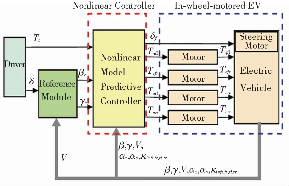
Fig.5 Active steering controller based on MPC(Reprinted with permission from Ref. [85]. Copyright 2015, Elsevier)
Differential steering technology includes differential assisted steering and differential direct steering. Through controlling the drive torque difference among wheels, the longitudinal driving force can control the steering axle to complete the steering process, which depends on the kingpin offset and the steering trapezium mechanism. The differential assisted steering technology uses the non-steering wheel to generate the yaw rate to assist or fix the steering angle. Most studies use differential steering as an auxiliary coordinated control subsystem, which is integrated with other dynamics control systems to improve the vehicle stability and safety, including the coordination between differential steering control and direct yaw moment control[86-88]and the coordination between differential steering control and fault-tolerant control[89].
At present, research on steer-by-wire and differential steering focuses on the algorithm optimization of the simplified model and has achieved excellent results. The technical difficulties to be solved are as follows: simulation of the road sense for driver to get a better driving experience, integration control of differential steering and active steering system with other chassis subsystems, the improvement of robustness and accuracy of steering control strategy under high and low speed conditions, and hardware structure integration of steer-by-wire system and hub motor driving system.
4.2.2Directyawmomentcontroltechnology
The research on direct yaw moment control (DYC) of the hub motor driving system adopts hierarchical control method, where the upper layer calculates the total yaw fix moment through the model-based method, and the lower layer optimizes the distribution of drive and braking torque. The traditional PID tracking control is greatly affected by external disturbances. In Ref. [90], a state feedback controller based on the extended kalman filter (EKF) algorithm is established to improve the vehicle transient stability and ensure the neutral steer. As the control performance is affected by model simplification, parameter uncertainty, and external disturbance, robustness becomes an important evaluation index. Ref. [91] proposes a gain scheduled robust linear quadratic regulator (RLQR, as illustrated in Fig.6[91])) for direct yaw moment control based on the 7-DOF vehicle model to obtain stronger robustness of the control system. Sliding mode control is a widely used robust control algorithm, but serious chattering problem occurs. So the use of the second-order sliding mode (SOSM) controller[92]becomes a feasible method for chattering suppression which can be applied in direct yaw moment control. Direct yaw moment control may interfere with other dynamics control systems. Therefore, some scholars proposed to integrate and coordinate the DYC system with other systems such as the active front wheel steering (AFS)[93]to take yaw stability and other performance indexes into consideration.
Direct yaw moment control improves vehicle stability and maneuverability by controlling yaw velocity. At present, studies concentrate on the optimization of the upper control algorithm,which fail to achieve the optimization of the multi-objective torque coordinated allocation in the lower layer controller. Meanwhile, the contradiction between the complexity of the dynamics model and the real-time computing remains to be solved.
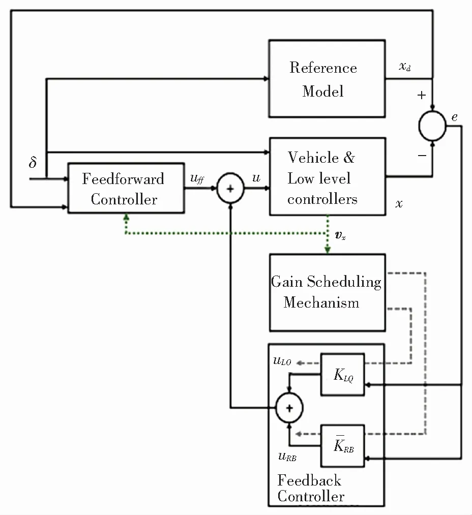
Fig.6 Control framework of RLQR(Reprinted with permission from Ref. [91]. Copyright 2018, Elsevier)
4.3 Hub Motor Drive Integrated Dynamics Control Technology
In view of the independent control characteristics of hub motor driving system, the integrated dynamics controller integrating lateral, longitudinal, and vertical dynamics is designed to improve the performance indexes such as steering stability and ride comfort. At present, research focuses on state observation, hierarchical control coordination strategy, control domain, and control weight division.
Integrated vehicle state observation is the premise of integrated dynamics control technology. The hub motor driven chassis is a multi-input and multi-output redundant driving system, which needs to be innovated based on the conventional chassis controller. In Ref. [94], a control framework which integrates basic chassis controller (BCC) and torque vector controller (TVC) is proposed (Fig.7[94]). Through combining strategy of torque distribution and active rear axle steering, it improves active safety, steering stability, economy of energy consumption, wheel tire wear coordination, and power battery charging and discharging safety for three-axle electric bus.
The hierarchical coordination strategy of integrated dynamics control conducts torque distribution based on the chassis control subsystem model[95]. In Ref. [96], combining the active front wheel steering and direct yaw moment control reduced the disturbance of modeling uncertainty, and simultaneously controlled the slip rate and yaw rate. Considering the ride comfort as the overall goal, Ref. [97] set different control weights for steering, braking, and suspension systems, and the integrated optimization was carried out by non-dominant sorting genetic algorithm (NSGA). The hub motor failure will seriously affect the vehicle stability and safety, so the comprehensive fault diagnosis strategy of the hub motor is needed in the integrated dynamics control[98]. Meanwhile, considering that the attention of each vehicle performance index is different under different working conditions, different chassis subsystems need to be selected for reconstruction and coordinated control[99].
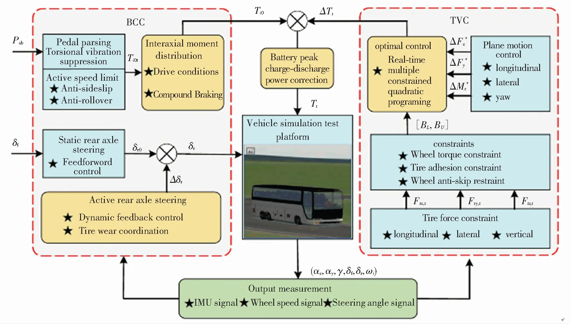
Fig.7 Vehicle integrated control framework structure(Reprinted with permission from Ref. [94]. Copyright 2018)
Hub motor drive integrated dynamics control technology needs to synthesize different performance indexes such as stability and safety based on the longitudinal, lateral, and vertical dynamics. It also needs to combine with the machine learning algorithm to identify driver intent and determine the control weights of each subsystem. It is also important to ensure the strong robustness and high accuracy of the real-time control strategy under different working conditions. Meanwhile, fault-tolerant control strategy based on the comprehensive fault diagnosis is essential.
5 Vehicle Development Direction of Hub Motor Driving System
With the trend of electrification, intelligentization, network connection, and sharing of vehicles, chassis technology has become one of the disruptive technological innovation of electric vehicles. The application of hub motor drive and wire control technology improves the dynamics characteristics and control performance of electric vehicle chassis, and creates a new development direction for chassis technology.
5.1 Technological Change of Hub Motor Drive Wire-Controlled Chassis
The emergence of hub motor drive and wire control technology improves the vehicle performance (Table 2[100]) such as handling performance, which is more suitable for the future intelligent traffic environment[100]. The hub motor can realize the independent control of each wheel and improve the performance of ABS, TCS, and ESC by controlling the motor torque. Its high response precision and near-zero delay response characteristics greatly improve vehicle performance.
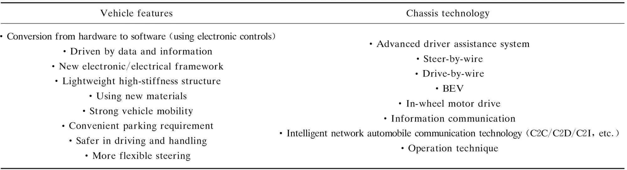
Table 2 Hub motor drive vehicle innovative chassis frame and performance improvements
Although hub motor drive vehicles have incomparable advantages over traditional vehicles, there are still constraints in their structure and control strategy, which requires researchers to explore the following development directions.
5.2 Hub Motor Drive Structure and Function Integration/Modularization
Combined with the suspension system and steering system, the modular hub motor driving system adopts the wheel-side steering. It can realize a variety of steering modes including fast lane changing, side parking, and small radius steering, which improves the vehicle flexibility. Adopting the modular hub motor driving system realizes the rapid replacement configuration of different vehicles, so that the wheelbase and vehicle size can be freely changed. Universality is adopted as the evaluation index of the modular hub motor driving system.
At present, the hub motor drive structure is only modified from the traditional chassis, and problems such as limited layout space, increasing unsprung mass, large rotary inertia, and vertical negative effect still exist. The structural integration technology such as integrated vehicle suspension and in-wheel damping has become an important solution.
5.3 Multi-Variable and Multi-Objective Optimization System Design for Hub Motor Driving System
At present, most studies focus on the single component structure optimization, which may interfere with other components in the hub motor driving system, resulting in the performance degradation of the overall system. The model precision of heating sources such as the hub motor and the brake needs improving, and the fluid-solid thermal coupling analysis needs to be carried out by considering the temperature and stress as optimization objectives. Based on the overall model of hub motor driving system, the lightweight technology needs to be realized by considering different structural parameters such as strength, mass, and size as optimization objectives. The above-mentioned technologies are to be relied on the multi-variable and multi-objective optimization system, which is one of the development trends of structure optimization technology in the future.
5.4 Intelligent Tires with Sensors
Hub drive vehicles have unique advantages such as four-wheel steering, small radius steering, and crab motion, but the tire wear is increased. Meanwhile, the dynamics control algorithm and fault diagnosis strategy based on road surface recognition also generate real-time data demand for tires. Therefore, the realization of new intelligent tire technology including the application of sensors to collect the real-time data of tire pressure, temperature, and wear, as well as communication with other vehicles has become an important condition for the popularization of hub motors drive vehicles.
5.5 Hub Motor Driving System Control Technology
5.5.1Combinationofadvanceddrivingassistantsystemandmodel-baseddynamicscontrol
Advanced driving assistant system (ADAS) uses sensors information and vehicle to X (V2X) technology to evaluate the environment and make a risk judgment, and ensures vehicle safety by adjusting vehicle posture and adopting active control intervention. However, it is susceptible to sensor accuracy and external noise interference. The model-based dynamics control of the hub motor drive vehicles reduces the ADAS dependence on environmental information, and greatly improves the vehicle dynamics performance and handling performance. Therefore, how to coordinate the ADAS and dynamics control becomes an issue worth discussing.
5.5.2Dynamicscontrolcombinedwithdriverintent
At present, the research on driver characteristics and behavior intention identification mainly focuses on how to establish the driver behavior model and how to identify the driver's intention, which is generally applied to the driving assistance system to fix the driver's behavior and lacks the interaction with the vehicle dynamics control. Therefore, the study of chassis dynamics control combined with the identification of driver behavior model and driving style will be one of the research emphases in the future.
5.5.3Controlsystemself-diagnosisandfaulttolerancestrategy
As the main power source, the hub motor driving system guarantees the vehicle dynamics performance and safety. Therefore, the active fault self-diagnosis algorithm is required. By combining the model-based multi-feature parameter fault diagnosis method with the state estimation method based on machine learning algorithms such as neural network, improving the self-diagnosis strategy accuracy becomes one of the main tasks of future electronic control system.
When the fault is determined through self-diagnosis strategy, maintaining the original control strategy will cause the instability phenomenon such as rollover and vehicle deviation, which will seriously threaten driver’s safety. Therefore, it is one of the important development directions of vehicle dynamics control technology to study vehicle fault tolerance strategy based on self-diagnosis technology and external environment information.
5.5.4Controltechnologycombinedwithintelligentnetworktechnology
Through the V2X technology, intelligent coordination work is carried out with roadside infrastructure, vehicle, pedestrian, road, network, or cloud to improve vehicle driving stability. The combination of intelligent network technology has become one of the latest trends in the development of hub motor drive control technology. The multi-vehicle queue coordination and vehicle-road coordination control based on the V2X technology and vehicle-mounted sensors can be combined with longitudinal, lateral, and integration dynamics control. The cloud controller can combine the road information (such as ramps and curvature) and traffic information (such as traffic flow and traffic lights) to optimize vehicle speed and gear, while considering the active steering and active suspension control to improve vehicle performance. Multi-vehicle coordinated control technology is implemented to improve vehicle stability and reliability, where communication delay is reduced through communication protocol optimization and network fault-tolerant control algorithm.
6 Conclusions
The development of the hub motor driving system will greatly improve the performance of new energy vehicles. It can be used as a platform for the future intelligent traffic environment to ensure the vehicle safety and driving experience. This paper summarizes the main research in the field of hub motor driving system in the last decade. Firstly, it summarized the present status of hub motor drive vehicle, and analyzed the technical driving scheme for different vehicles. Then the structural integration optimization technology and the research progress of existing longitudinal, transverse, and dynamics integration control technology of hub motor drive vehicle were introduced. Finally, this paper put forward the future development directions of hub motor driving technology.
With the improving demand for vehicle dynamics performance, safety, economy, and ride comfort, hub motor driving technology will become the key direction of chassis innovation. In the future, research on hub motor driving technology will be improved from component optimization to overall performance improvement. Also, robustness, accuracy, and real-time performance of the overall optimization technique and the control algorithm are required to be verified by real vehicle test under complex conditions. The hub motor driving technology will advance towards the direction of module integration, informatization, intelligentization, and network connection, which can improve the vehicle performance and help the construction of intelligent traffic environment.
 Journal of Harbin Institute of Technology(New Series)2020年3期
- Journal of Harbin Institute of Technology(New Series)的其它文章
- Evolution Toward Artificial Intelligence of Things Under 6G Ubiquitous-X
- Evaluation Method of Output Waveform Quality for Neutral-Point- Clamped Three-Level Converter
- Review: Scalable Fabrication of Polymeric Nanofibers from Nano- Spinning Techniques to Emerging Applications
- Controlled Movements in Superlubric MEMS
- Review: Recent Progress on Poly(ether ether ketone) and Its Composites for Biomedical, Machinery, Energy and Aerospace Applications
- Modified Adsorption Capacity to Space Molecular Pollutant of Zeolite via Interface Engineering with Atomic Layer Deposition