
2-D eddy resolving simulations of flow past a circular array of cylindrical plant stems *
2018-05-14 01:43:14KyoungsikChangGeorgeConstantinescuSanghyunPark
水動力學研究與進展 B輯 2018年2期
Kyoungsik Chang , George Constantinescu , Sanghyun Park
1. School of Mechanical Engineering, Ulsan University, Ulsan, Korea
2. Civil and Environmental Engineering Department, IIHR-Hydroscience and Engineering, Stanley Hydraulics
Laboratory, The University of Iowa, Iowa City, USA
3. Korea Aerospace Research Institute, Daejeon, Korea
Introduction
Flow around a porous cylinder is relevant for many engineering problems. A major type of applications for hydraulics and river engineering is related to understanding the effect of the presence of vegetated canopies on flow, turbulence structure and transport(e.g., nutrient, sediment erosion/deposition inside and around the boundaries of the vegetated canopy). For example, the presence of a layer of vegetation in a river can significantly modify the overall flow resistance and create regions of high turbulence production.This is particularly true for cases in which the porosity,or equivalently the solid volume fraction (SVF), of the porous (vegetated) layer is highly inhomogeneous. In many cases, regions of high SVF alternate with regions of low or negligible SVF. One extreme case considered in the present work is that of an isolated patch of vegetation. This corresponds to the case when a region of high SVF is surrounded by large regions of low or negligible SVF. Similar types of problems are encountered in the atmosphere, where the presence of patches of vegetation can alter the flow structure near the ground[1,2]. Other relevant examples include flow past bridge piers containing multiple piles, heat transport induced by flow around tube bundles in heat exchangers, effect of tower arrangement in wind turbine farms, dispersion in flow past large buildings in urban areas.
In some cases, the isolated patch of vegetation can be emerged. If one neglects the near bed and free surface effects, the flow is close to homogeneous away from the bed and the free surface. In most experimental and numerical studies of vegetated flows,the plant stems are modeled as small solid rigid cylinders. For such cases, one can try to understand the physics of these flows by first considering the case of a patch of a certain shape formed of long solid cylinders. In the case of 3-D numerical simulations,this reduces to imposing periodic conditions in the vertical direction, assuming that the plant stems are oriented vertically. If 3-D effects are not expected to be important (e.g., the case of relatively low Reynolds numbers), 2-D simulations of such flows can be conducted to understand the flow structure and to quantify the drag forces on individual cylinders.Accurately quantifying the drag forces on the cylinders within the patch is very complicated to achieve experimentally but is critically important for specifying the drag constant in simpler numerical models used to study flow in vegetated channels in which the flow past the individual cylinders is not resolved.
To reduce the number of variables characterizing the problem (e.g., angle of attack) one will focus on the case of a circular porous cylinder with emerged cylinders. The main parameters are the diameter of the porous cylinder,D, the diameter of the small solid cylinders,d, the spacing and arrangement of the small cylinders in the patch, the incoming flow velocity and the properties of the fluid. The SVF is defined as the ratio of the total volume of the small cylinders to the volume of the porous cylinderN( =Nd2/D2, whereNis the number of small cylinders in the circular patch)
Both direct numerical simulation (DNS) and large eddy simulation (LES) were used to simulate flow past isolated solid cylinders and past arrays of cylinders and wall-mounted obstacles (e.g., cubes).LES is a good alternative to DNS because it requires substantially less computational resources, especially as the porous cylinder Reynolds number becomes relatively large (e.g., 104or larger). Most of previous numerical studies of flow past arrays of cylinders considered the case of one solid cylinder with symmetric/periodic boundary conditions[3]or arrays containing a small numbers of cylinders (2-10)[4,5].Such configurations are not exactly representative for the case of patches of vegetations where the patch generally contains a large number of cylinders, while the SVF’s are generally less than 20%.
Besides numerous studies focusing on isolated cylinders and bluff bodies[6], several experimental and numerical investigations were recently conducted for circular patches of cylinders containing a relatively high number of solid cylinders. The experimental study of Zong and Nepf[7]provides a detailed description of the turbulent wake behind a circular array of cylinders placed in an open channel, which mimics a patch of emergent vegetation in a river. In particular,their study investigated the variation in the wake characteristics with the SVF and other flow and geometrical parameters. Nicolle and Eames[8]used 2-D DNS to study flow structure within and downstream of a circular porous cylinder containing between 7 and 133 small rigid circular cylinders. The range of the SVF investigated in their study was between 1.6% and 30% and the porous cylinder Reynolds number was of the order of 103. DNS results were used to estimate the drag forces on the individual cylinders as a function of the SVF. They observed that for SVF<5% the cylinders have close to uncoupled wake patterns, similar to those observed past isolated cylinders. For SVF>15%, strong interactions between the small cylinders were observed and the wake flow past the porous cylinder was similar to the one observed past a non-porous cylinder(SVF=100%) of identical diameter,D. For 5%<SVF<15%, a shear layer is generated at the side of the porous cylinder, similar to the separated shear layer (SSL) forming on the sides of non-porous cylinders and the force direction on the individual cylinders is close to steady. By contrast, the direction of the drag force on the individual cylinders is subject to large variations in time for the other two regimes.
In the present study, 2-D simulations of the flow around a circular array of cylinders were conducted with three different SVFs (8.8%, 14.5%, 21.5%).Similar to the aforementioned DNS investigation, the present study neglects 3-D effects which, given the relatively low Reynolds number (Re=2100,Red=100, whereReis defined with the viscosity, ν, the diameter of the porous cylinder,D, and the incoming steady velocity,U∞, andRedis defined with the diameter of the solid cylinders,d) used in the simulations, is an acceptable approximation. For lab conditions, this Reynolds number corresponds toD=0.2 m andU∞~ 0.01m/s. Such low-velocity simulations are relevant for very shallow and slow flow conditions that are sometimes encountered when patches of vegetation are present on the floodplains and inside river-bank embayments. The model is then tested forRe=21000 which is in the middle of the range at which lab experiments of these flows are normally performed. For example, Zong and Nepf[7]experiments were performed for 10000<Re<40000. For such cases, present simulations do not capture 3-D effects. Still, some of the main relevant quantities such as the drag coefficient of the porous cylinder are expected to be fairly accurately predicted.
The study discusses the effect of the SVF on the strength of the bleeding flow, the main parameters describing the wake length, the large scale vortex shedding, the strength of the wake-to-wake interactions within the porous cylinder and on the amplitude of the unsteady oscillations of the total drag force on the porous cylinder. Two main research questions we try to answer in the present study is whether LES conducted on coarser meshes can provide results of comparable accuracy to those of DNS for flow past patches of cylinders in which the flow past the individual solid cylinders within the array is resolved,and if LES on fairly coarser meshes can be used to perform simulations at high Reynolds numbers where the wake is strongly turbulent. Moreover, in the present study numerical results are used to describe in more details the effect of the SVF on the unsteady forces acting on the individual cylinders and on the wake structure in the mean flow, following the analysis done by Zong and Nepf[7]based on experimental measurements.
1. Numerical method and simulation setup
The numerical solver used in the present work is a finite-volume LES code[9,10]that solves the incompressible Navier-Stokes equations. The conservative form of the Navier-Stokes equations is integrated on non-uniform Cartesian meshes. The algorithm is second order accurate in both space and time. All operators in the momentum and pressure equations are discretized using central discretization. The numerical method discretely conserves energy. This ensures robustness at relatively high Reynolds numbers and/or coarse meshes while using strictly non-dissipative discretization to solve the Navier Stokes equations[9,10].The dynamic Smagorinsky model was used to calculate the sub-grid scale viscosity[9,11]in the base cases, but results are also included for some simulations conducted using the standard, constant coefficient, Smagorinsky model[12]. The solver was validated for many applications relevant to the one discussed in the present study including flow past an open cavity[13], flow past sinusoidal dunes[14], constant density and stratified flows in channels containing obstacles[15].
The Reynolds number based on the bulk velocity of the freestream (U∞) and the diameter of porous cylinder (D) isRe=2100 in the simulations for which the flow physics is investigated. At this Reynolds number, the flow instabilities in the separated shear layers of the solid cylinders and of the porous cylinders are sufficiently strong and regions of weak turbulence are expected to occur in the wake.Given the low value of the cylinder Reynolds number(Red=100), the flow within the patch is expected to be unsteady and to remain two-dimensional[8]. Thus,the flow is expected to remain quasi 2-D inside the porous patch and the near wake of the porous cylinder in the simulations withRe=2100. Preliminary 3-D simulations of the most unsteady (SVF=21.5%,Re=2100) case performed in our group confirmed this.
The number of solid cylinders of diameterd=0.048Din the simulations with SVF of 8.8%,14.5% and 21.5% was equal to 39, 64 and 95,respectively. The main parameters of the three cases are compared in Table 1. The ratiod/D=0.048 is within the range used in most laboratory experiments of these flows. For example, 0.014 <d/D<0.050 in the experiments of Zong and Nepf[7]and 0.015<d/D< 0.128 in the experiments of Chen et al.[16].The effect of increasingd/Dwhile maintaining a constant SVF will be felt mainly via the decrease inaD, whereais the frontal area per unit volume for the array[7]. For constantD, the total drag force on the porous cylinder is proportional toaD. Thus patches with sameDbut with largerd/Dwill be characterized by a smaller global time-averaged stream wise drag coefficient. However, the dominant frequency associated with shedding of billow vortices in the wake of the porous cylinder is not expected to be affected. The same is true for the nondimensional Strouhal number defined with the solid cylinder diameter,d, which characterizes the main shedding frequency associated with shedding of wake vortices inside the porous patch (Std=0.25-0.27 forRed=O(102)).

Table 1 Simulation parameters and test cases
Figure 1 shows the cylinder arrangements for each of the three cases together with the numbers used to identify each cylinder in the patch. The flow conditions and the (staggered) arrangement of the solid cylinders in the array are the same with those used in the numerical study of Nicolle and Eames[8]. This is important given that a main goal of the present study is to estimate the predictive capabilities of 2-D LES compared to 2-D DNS for this type of flows. The simulations were conducted in nondimensional form.The cylinder diameterDand the steady incoming flow velocityU∞were used to nondimensionalize all the variables. The length of the computational domain was 20D. The width of the computational domain was 14D. The number of grid points in the stream wise and span wise direction was 1500 and 820,respectively. The grid resolution around the porous cylinder is set to Δx=Δy=0.002Dto resolve the attached boundary layer and the separated shear layers of the individual cylinders and of the porous cylinder.Away of the porous region, the grid was gradually coarsened. Preliminary simulations were conducted with a larger domain size (length 30D, width 20D)for the SVF=21.5% case with a similar mesh density (2200 and 1200 grid points in the stream wise and span wise directions, respectively) inside and away from the porous cylinder region. The Strouhal number associated with the shedding of billows in the wake of the porous cylinder was basically identical in the two simulations (St=0.25). The global stream wise drag coefficient for the porous cylinder was 1.75 in the coarser mesh simulation and 1.77 in the finer mesh simulation. The amplitude of the total stream wise drag coefficient oscillations were 0.80 and 0.78 in the simulations performed with the coarser and finer mesh,respectively.
The incoming flow was steady and uniform and the solid surfaces of the cylinders were treated as no slip walls. At the outflow, a convective boundary condition was used. The time step was 0.002D/U∞.Statistics were calculated after the flow became statistically steady, which took about 40D/U∞. The time interval used to calculate flow statistics was about 50D/U∞. We checked that this time interval was long enough to obtain converged first and second order statistics.
Besides the 2-D LES conducted withRe=2100 for porous cylinders, several additional simulations were conducted. They include a 2-D LES atRe=2100 for the solid cylinder case and an unsteady RANS (URANS using the standard SSTk-ω model,URANS simulations were conducted using Fluent) atRe=2100 for the SVF=21.5% case. These simulations serve to highlight the differences in the flow structure between flow past porous and solid cylinders and to assess the success and limitations of the RANS approach that is commonly used in practical applications of such flows (e.g., flow in channels containing patches of vegetation). Given that the effect of the sub-grid scale model is relatively small atRe=2100, additional 2-D LES were conducted at a much higher Reynolds number (Re=2100), where well-resolved DNS becomes computationally very expensive. The mesh was the same in the 2-D LES atRe=2100 and 21000. Such calculations demonstrate the utility of the LES approach for practical applications where the porous cylinder Reynolds number is relatively high. The role of the turbulence model is investigated for the SVF=21.5% case for which,besides the dynamic Smagorinsky model, calculations are performed using the constant coefficient Smagorinsky model (C=0.01) and URANS. The mesh resolution in the 2-D URANS was comparable to that used in 2-D LES.
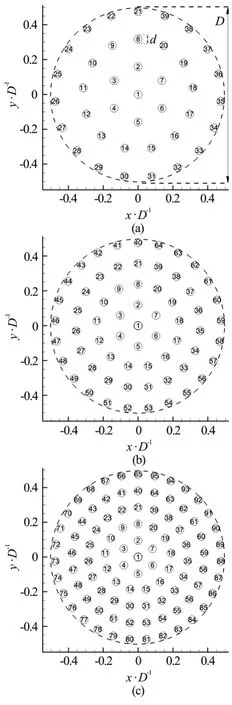
Fig.1 Cylinder arrangements within the circular patch. The numbers denote the index of each cylinder in the array
2. Results
Before discussing results for porous cylinders, it is important to establish that the flow around each cylinder in the patch is sufficiently resolved in terms of the grid resolution used in the simulations with a porous cylinder. To check this, a series of simulations of a test case containing only one solid cylinder of diameterdwas set up and run at a cylinder Reynolds number (Red) of 100. The LES model was turned on in these simulations. However, the dynamic Smagorinsky model correctly predicted negligible values of the subgrid-scale viscosity in the whole flow domain. So, the predicted flow in these simulations was laminar and unsteady, as also observed in corresponding experiments. The purpose of these simulations was to determine the minimum grid spacing needed to obtain a grid independent solution and to accurately resolve the mean flow and vortex shedding past the solid cylinder. Results in Fig.2 correspond to the maximum grid spacing around the cylinder that ensured obtaining a grid independent solution for this simpler test case ( Δx=Δy=0.04d,which corresponds to 0.002D). Further refining the mesh did not result in significant changes of the solution or in a better agreement with experimental data. In all these simulations the time step was sufficiently low to resolve the dominant frequencies associated with the wake vortex shedding. Once the required resolution of flow around an isolated cylinder was determined, the same mesh density was used in the simulations containing a porous cylinder inside the porous region (Re=2100 corresponding toRed=100). The variation of the pressure coefficient with the polar angle is plotted in Fig.2. Very good agreement with experimental results obtained at comparable Reynolds numbers (Re=100)[17]is observeddin Fig.2. The time averaged drag coefficient and the length of the recirculation bubble predicted by our simulation are 1.36 and 1.41, respectively. These values are within 2.3% and 0.7% from the values(1.33 and 1.42, respectively) given in the literature[18].
The other requirement in terms of sufficiently well resolving the flow past the porous cylinder is to accurately resolve the flow past the porous cylinder,and in particular the SSLs region. The requirement of resolving around and behind the porous cylinder are the same as the ones needed to resolve the flow past a solid cylinder of equal diameter at the same Reynolds number. An additional 2-D LES simulation was performed for the case of a solid cylinder of diameter equal to the one of the porous cylinder (d=D,Red=2100). The mesh density was Δx=Δy=0.002Dclose to the cylinder and in the region containing the SSLs. The mesh spacing was increased gradually in the near wake and on the lateral sides of the cylinder. Again, the distribution of the pressure coefficient on the solid cylinder was found to be very close to that predicted by DNS (Fig.2). The mean drag coefficient predicted by 2-D LES was equal to 1.7. This value is close to the one (1.67) predicted by a DNS performed by Singh and Mittal[17]forRed=2000. These results show that the present LES code is capable to accurately simulate flow past solid cylinders, at least for the Reynolds numbers that are relevant for the present study.

Fig.2 Pressure coefficient (C p ) distribution with the polar angle θ for an isolated small cylinder at Red =100 and for an isolated large cylinder, Red =2100 of the same diameter as the porous cylinder (d=D)
An additional finer mesh simulation was conducted for the SVF=21.5% case, for which flow unsteady effects are the strongest. Doubling the number of grid points did not result in significant changes (less than 3%) in the predicted values of the mean forces on the individual cylinders, mean total stream wise drag coefficient, amplitude of the oscillations of the total drag and lift coefficients of the porous cylinder and the Strouhal number associated with vortex shedding past the porous cylinder.
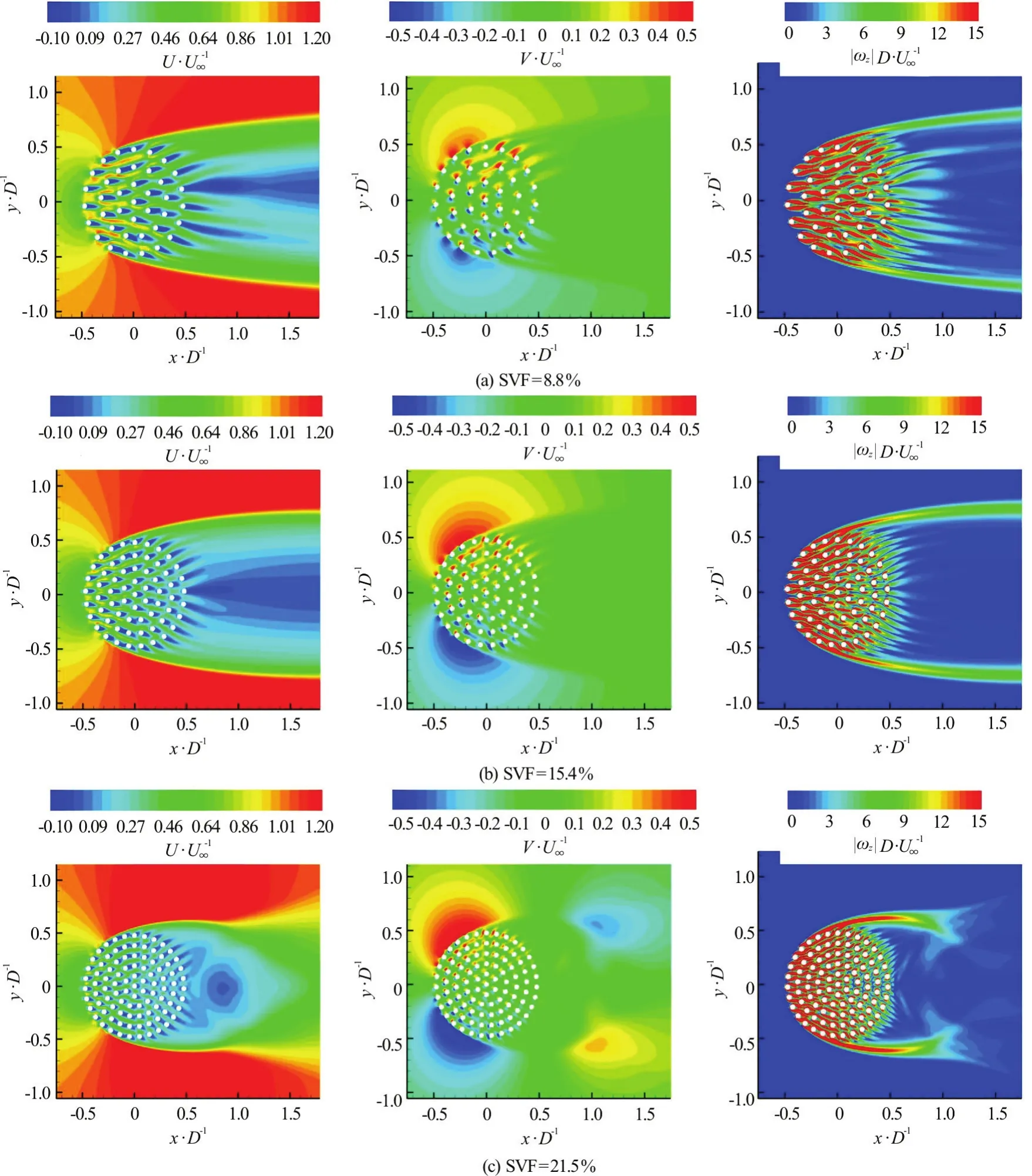
Fig.3 (Color online) Time averaged flow fields (R e=2100)
Figure 3 shows the nondimensional stream wise velocity,U/U∞, span wise velocity,V/U∞and outof-plane (vertical) vorticity magnitude,D/U∞,contours in a region containing the porous cylinder and the near wake. All the variables are nondimen sionalized usingDandU∞. As the SVF increases,the strength of the bleeding flow through the porous cylinder decreases. The presence of a strong bleeding flow impedes the natural interactions of the SSLs,which result in the alternate shedding of wake billows(von Karman vortex street). So, as the SVF decreases,the length of the SSLs increases. The deceleration of the flow around the upstream face of the porous cylinder is more pronounced in the simulations with a lower SVF. As a result, the strength of the adverse pressure gradients generated around the upstream face of the porous cylinder is larger in the simulations with a larger SVF. In all three cases, SSLs form on the sides of the porous cylinder, similar to the canonical case of a solid cylinder. However, for the reasons explained before, the length of the SSLs decreases with the increase of the SVF, while the amplification of the vorticity within the SSLs increases with the SVF. In all three cases, most of the bleeding flow is diverted laterally toward the SSLs forming on the sides of the porous cylinder (e.g., see the contour plots ofVin Fig.3). The strength of the lateral (span wise)component increases with the SVF. Only a small percentage of the bleeding flow is moving along the stream wise direction close to the centerline of the cylinder. Most of the bleeding flow exits the porous cylinder at polar angles less than 90°, consistent with the direction of the drag force on the cylinders in Fig.4 and the contours of the lateral velocity in Fig.3.This also explains some of the features of the distributions of the time averaged drag forced acting on the cylinders,(iis the index used to identify eachcylinder in the patch, see Fig.1),in Fig.4. For example in all three cases,, the force on the cylinders situated in t he re gions withx/D>0 is much smaller compared to the drag forces acting on the cylinders situated in the region withx/D<0.This indicates that the bleeding flow at the back of the cylinder is very week in all cases. Within the later region, the mean drag force is not oriented along the stream wise direction rather it has a strong (lateral)component toward the two SSLs. This is especially true in the simulations with SVF=15.4% and 21.5%.One should also mention thatis negligible for some of the cylinders in the array, while having significant values for other cylinders situated in the same region of the patch. This is simply because that cylinder is situated at most times in between the SSLs of another cylinder, which is a region of small velocity magnitude. In particular, this is the reason why very small values of the mean drag force are observed for some of the cylinders situated close toin the SVF=8.8% case (Fig.4(a)) in which the flow within the porous patch is steady.
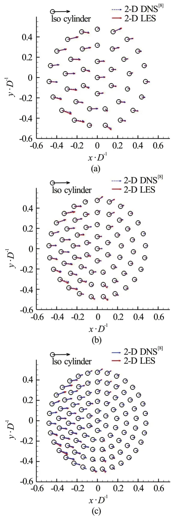
Fig.4 (Color online) Time-averaged nondimensional drag forces acting on the cylinders within the patch (Re=2100) .LES results (red arrows) are compared to 2-D DNS results of Nicolle and Eames[8] (blue arrows). Also shown in the top left corner is the stream wise drag force acting on one isolated solid cylinder (black arrow).(c) also contains results of 2-D DNS results (black arrows) obtained on a finer mesh using the present code.Results of 2-D DNS on a finer mesh are indistinguishable from those of 2-D LES
The drag/lift force on each individual cylinder is calculated from the integration of the pressure force and viscous force on that cylinder. An interpolation procedure is used to obtain the velocity vector at a small distance from the cylinder surface and pressure on the cylinder surface. The largest mean stream wise drag forces are observed for the cylinders directly exposed to the flow. Given the staggered arrangement of the cylinders in the patch, this roughly corresponds to the first two rows with respect to the circumference of the porous cylinder. Still, in all three cases, the magnitude of the drag force on the cylinders exposed to the incoming flow is significantly smaller (e.g., by about 30%, 50% and 70% for cases with SVF=8.8%,15.5% and 21.5%, respectively) than the drag force observed on an identical isolated cylinder (see blue line in Fig.4). This is because the cylinders within the patch contribute to the formation of a significant adverse pressure gradient around the upstream face of the porous cylinder. This pressure gradient is not present in the case of an isolated cylinder. Thex/Dvalues at which drag force magnitude on the cylinders within the array is comparable (less 30% lower) with the one on the cylinders directly exposed to the flow decrease with increasing SVF. This location isx/D~ 0.1 for SVF=8.8% ,x/D~-0 .1 for SVF=15.4% andx/D~-0 .2 for SVF=21.5%.
Also plotted in Fig.4 are the forces predicted by the 2-D DNS of Nicolle and Eames[8]as well as 2-D DNS obtained on a finer mesh (resolution was two times higher in both directions compared to standard mesh used in LES) using the present code for the SVF=21.5% case. The agreement with the calculations of Nicolle and Eames[8]is excellent for most of the cylinders in the array for all three cases. Moreover,the DNS and LES results for the SVF=21.5% case obtained using the present code are basically undistinguishable. This serves as further prove that LES can accurately predict the mean forces on the individual cylinders.
Using the time-averaged force vector acting on each cylinder, global and individual coefficient of(stream wise) drag (DxGandDxi) were calculated.Following Nicolle and Eames[8], their expressions are:
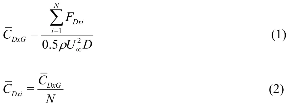
where the frontal area in the 2-D case isDandFDxiis the mean stream wise mean drag force acting on cylinderi.
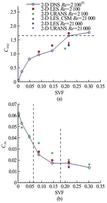
Fig.5 (Color online) Global(DxG ) and individual(Dxi)time-aver aged stream wise drag coefficients for the porous cylinder.Included are results for2-DLESatRe=2100 and Re =21000, 2-D unsteady RANS at Re=2100andRe =21000,2 -DLES p er formed with a constant Smagorinsky model(CSM)atRe=21000 and 2-D DNS predictions of Nicolle and Eames[8].The inset in the right frame served to better see differences between predictions for SVF=21.5%. The horizontal dashed line in the left frame shows the value ofDxGpredicted for the solid cylinder case (SVF=100%)
As the SVF increases, the global drag coefficient increases while the individual drag coefficient decreases. The present results are compared with those of Nicolle and Eames[8]in Fig.5. Very good agreement is observed. One should mention that due to the Cartesian grid used, the surface of the circular cylinders in the present study is not very smooth. Also shown in Fig.5(a) using a dashed line is the value (1.7)obtained from an additional simulation performed with our code of the flow past an isolated solid cylinder of diameterD, corresponding to the SVF=100% case. Present results suggest that for SVFs larger than 20% the global drag coefficient of the porous cylinder,DxGis close to the value observed for a solid cylinder of same diameter.
Additional simulations performed for SVF=21.5% show that the effect of increasing the Reynolds number is to decreaseDxG(e.g., by about 18%, asReis increased from 2100 to 21000) and that the effect of the sub-grid scale model on the value ofDxGis fairly negligible. At both Reynolds numbers, URANS predicts a smallerDxGcompared with LES. The difference decreases with increasing Reynolds number (e.g., atRe=21000 URANS predictsDxG=1.20, while LES with a dynamic sub-grid scale model predictsDxG=1.41).
For the cases where the drag and lift coefficients are not steady, two other important flow parameters to be compared between present LES and the DNS of Nicolle and Eames[8]are the nondimensional frequency (Strouhal number) of the oscillations of the total span wise drag force and the amplitude of the oscillations of the stream wise and span wise drag forces (the oscillations are regular in a very good approximation, as also see from Fig.10). For the SVF=21.5% case, the Strouhal number predicted by LES is 0.25 (same as the dominant frequency in the wake induced by shedding past the porous cylinder given in Table 2), while DNS predicted 0.254. The amplitude of the total stream wise drag coefficient oscillations predicted by LES is 0.8, while the value inferred from Nicolle and Eames[8]is 0.74. The corresponding values of the amplitude of the oscillations of the total span wise drag coefficient are 0.23 and 0.21, respectively.
Figure 6 shows the time averaged stream wise velocity profiles along the centerliney/D=0. Following Zong and Nepf[7], the length of steady wake region (L1) is defined as the length behind the porous cylinder where the stream wise velocity assumes a small, close-to-constant value before starting to increase toward the free stream value. This value is denotedU1(Table 2). The ratioU1/U∞is expected to be mainly a function of the SVF[7]. The acceleration region of lengthL2, also called the wake recovery region, starts at the end of the steady wake region and ends where the rate of increase of the stream wise velocity toward the free stream valuebecomes very small[7]. The total wake length is defined asL=L1+L2. As shown in Table 2, bothL1andL2increase monotonically with the decrease in the SVF. Similar to the case of a solid cylinder(SVF=100%),L1=0 for the case with SVF=21.5%. In this case, the accelerating wake region starts at the back of the cylinder. The URANS solution for SVF=21.5% shows some marked differences with LES. URANS significantly over predicts the length of the separate d s hear layer (se e also Figs. 7(c), 7(d)) and the lengths of the steady wake and total wake (Table 2). In fact, the URANS solution for SVF=21.5% is closer to that obtained for SVF=15.4% using LES. The main reason for these differences are the much larger values of the eddy viscosity predicted by RANS compared to LES especially in the regions of large mean shear (e.g., in the SSLs of the porous cylinder). The SSLs are much more stable in the RANS case, where 2-D instabilities acting on the SSLs are strongly damped. For wake billows to form in the RANS simulation, the bleeding flow entering the near wake at the back of the porous cylinder has to loose most of its stream wise momentum (this takes a longer stream wise distance)before some large scale instabilities can develop over the downstream part of the SSLs and the ends of the SSLs can start interacting.
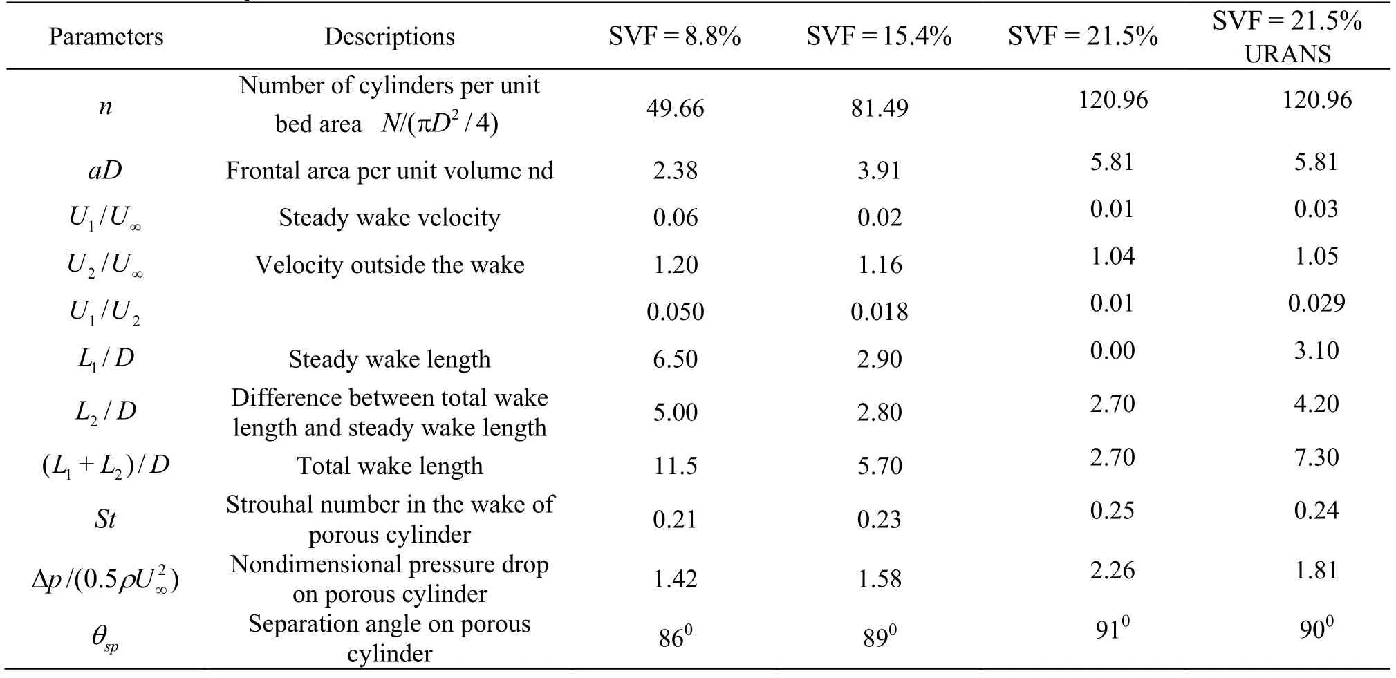
Table 2 Main wake parameters

Fig.6 (Color online) Time averaged stream wise velocity profiles at the center of porous cylinder (y/ D =0), L1 (steady wake length defined as the end location of the recirculation bubble), L2 =L-L1 (L: Total wake length defined as the location where the mean stream wise velocity reaches the free stream velocity). In the figure L1 and L2 are represented for case SVF=8.8%. Results are shown for 2-D LESat Re =2100 (8.8%<SVF<100%) (8.8%<SVF<100%)and2-D unsteady RANS at Re =2100 (SVF=21.5%)

Fig.7 (Color online) Instantaneous out-of-plane vorticity magnitude (ω zD/ U∞) contours (R e=2100)
Also shown in Table 2 is the maximum value of the stream wise velocity on the outer side of the porous cylinder and the SSLs. The increase of the stream wise velocity is due to the acceleration of the flow because of the obstruction imposed by the porous cylinder.This velocity is denotedU2. The values ofU1/U∞andU2/U∞are comparable to those determined experimentally in Zong and Nepf[7]at comparable SVFs.Results in Table 2 show that the nondimensional pressure drop on the porous cylinder,(Δpis calculated between the φ= 0oand φ=180opoints, where φ is the polar angle measured from the negativexaxis) increases monotonically with increasing SVF. This is expected be cause the st agnation pressure on the upstream face of the porous cylinder increases with the SVF. While URANS accurately predictsU1/U∞andU2/U∞compared to 2-D LES,it underpredicts by close to 20% the value offor the SVF=21.5% case.
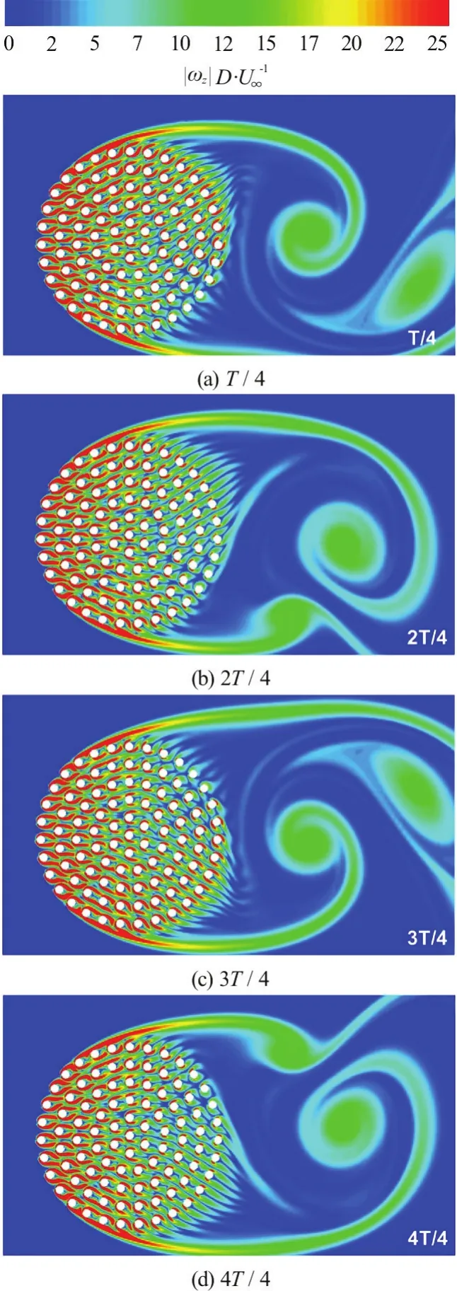
Fig.8 (Color online)Instantaneous out-of-planevorticity magnitude(ω zD/ U∞) contours during one period in the simulation with SVF=21.5% and Re =2100.Results are showing every quarter period (T/4)
The instantaneous out-of-plane vorticity magnitude contours in Fig.7 show that the von Karman vortex street is observed in all three cases (Re=2100,LES). The changes in the position of the SSLs and the alternate formation of wake billows is illustrated in Fig.8 for the SVF=21.5% case. As the SVF increases from 8.8% to 21.5%, the length of the SSLs decays from 8.0Dto about 1.5D. In the latter case the wake billows form just behind the cylinder, very similar to the case of a solid cylinder (SVF=100%).The counter-rotating billows are shed quasi-regularly and their strength is comparable, but not identical.This is due to the relative position of the cylinders within the patch that is not perfectly symmetrical with respect to the centerline. The study of Nicolle and Eames[8]also found that for porous cylinders with SVF>15%, the von Karman vortex street behind a porous cylinder looks qualitatively similar to the one observed in the case of a solid cylinder. As already discussed, the bleeding flow exiting the porous cylinder at polar angles larger thano90 is primarily oriented stream wise and away from the axis of the porous cylinder. The transverse component acts toward pushing the SSLs away from each other, while the stream wise component increases the length of the recirculation bubble behind the porous cylinder and further pushes away the eddies generated at the end of the SSL that curves toward the other SSL. This is why as the SVF decreases, the two SSLs are much longer and the interaction between them happens at a much larger distance behind the cylinder. Figures 7(a)-7(c)also shows that the distance between two consecutively shed billows decreases with the increase in the SVF. For the case of relatively low values of the SVF(e.g., for SVF=8.8% in Fig.7(a)), the bleeding flow is strong enough to result in shedding of largescale vortical eddies from the cylinders situated at or close to the back of the porous cylinder. These eddies are an additional source of large-scale vorticity for the steady wake region.
In SVF=21.5% case, the nondimensional frequency (St=fD/U∞, wherefis the dimensional frequency) at which billows are shed in the wake of the porous cylinder is 0.25, which is the same value as the frequency of total force drag coefficient in Fig.10.The dominant frequency decreases only very slightly with the decrease in the SVF (e.g., it is equal to 0.23 for SVF=15.4% and 0.21 for SVF=8.8%). The mean (time-averaged) polar separation angle on the porous cylinder, θsp, is close to 90% in all cases. This value is close to the one observed for solid cylinders(subcritical regime). URANS predictions ofStand θspare fairly close to 2-D LES (see results for SVF=21.5% in Table 2). URANS predictions of these two variables obtained for the case of a solid cylinder also show a good level of agreement with LES and DNS. Despite, the good agreement observed forSt, the wake structure shows some marked differences in between the URANS and LES calculations with SVF=21.5%. The coherence of the wake billows is much smaller in URANS and the billows start at a much larger distance from the back of the porous cylinder.
Figure 9 visualizes the vortical structure of the instantaneous flow within the porous cylinder. 2-D streamlines are added to give an idea about the direction of the flow and to visualize the recirculation bubbles forming behind the cylinders. Only the domain withy/D>0 is shown as the distributions are close to symmetrical on the two sides of the centerline. Strong wake-to-wake interactions are observed in all three cases. Several researchers[19-21]investigated flow patterns and induced force distributions for two tandem, side by side and staggered cylinders. In particular, Sumner et al.[19]identified six main distinctive flow patterns based on their experimental results: shear layer reattachment (SLR),induced separation (IS), vortex pairing and enveloping(VPE), vortex pairing, splitting and enveloping(VPSE), synchronized vortex shedding (SVS), and vortex impingement (VI). Details about these flow patterns are given in Sumner et al.[19]. As discussed below, such interactions are also observed in the porous cylinder cases investigated here.
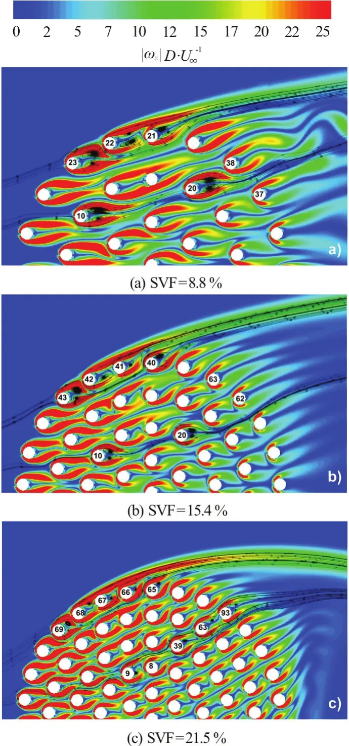
Fig.9 (Color online) Instantaneous out-of-plane vorticity magnitude (ω z D/ U∞) contours (R e=2100)
In the case with SVF=8.8%, the 2-D streamlines and vorticity magnitude contours between cylinders 23 and 22 and between cylinders 22 and 21 are characteristic of the shear layer reattachment (SLR)flow pattern. The inner shear layer (relative to the porous cylinder) of the upstream cylinder reattaches on the surface of downstream cylinder and outer shear layer of the upstream one is stretched in the stream wise direction. Flow pattern around cylinders 10 and 20 is characteristic of the VPE (vortex pairing and enveloping) pattern, but does not show unsteady oscillations in the present simulation. Other experiments or simulations have shown large temporal oscillations associated with the VPE pattern. This discrepancy is due to suppression and stabilization of wake flows from the upstream cylinder by the neighboring downstream cylinders. Cylinders 38 and 37 experience oscillatory vortex pairing, but the magnitude of the unsteady oscillations is fairly small compared to those observed for an isolated cylinder.Similar flow patterns are shown also in the simulation conducted for SVF=15.4% (Fig.9(b)). For example,cylinders 40, 41, 42 and 43 experience the SLR flow pattern, while cylinders 10 and 20 experience the VPE flow pattern. One interesting observation is that flow around cylinders 62 and 63, which are representative of cylinders situated at the back of the porous cylinder,are surrounded by basically steady flow despite the unsteadiness of the flow around the cylinders situated on the upstream side,x/D<0 of the porous cylinder. This is due to small cylinder Reynolds number of the cylinders situated in the former region where the bleeding flow between cylinders is very weak.

Fig.10 Time history of global stream wise drag coefficient,C DxG, (toplines)and span wise drag(lift)coefficient,C DyG, (bottom lines) for the porous cylinder (Re=2100). Results are shown for 2-D LES and unsteady RANS (SVF=21.5%)
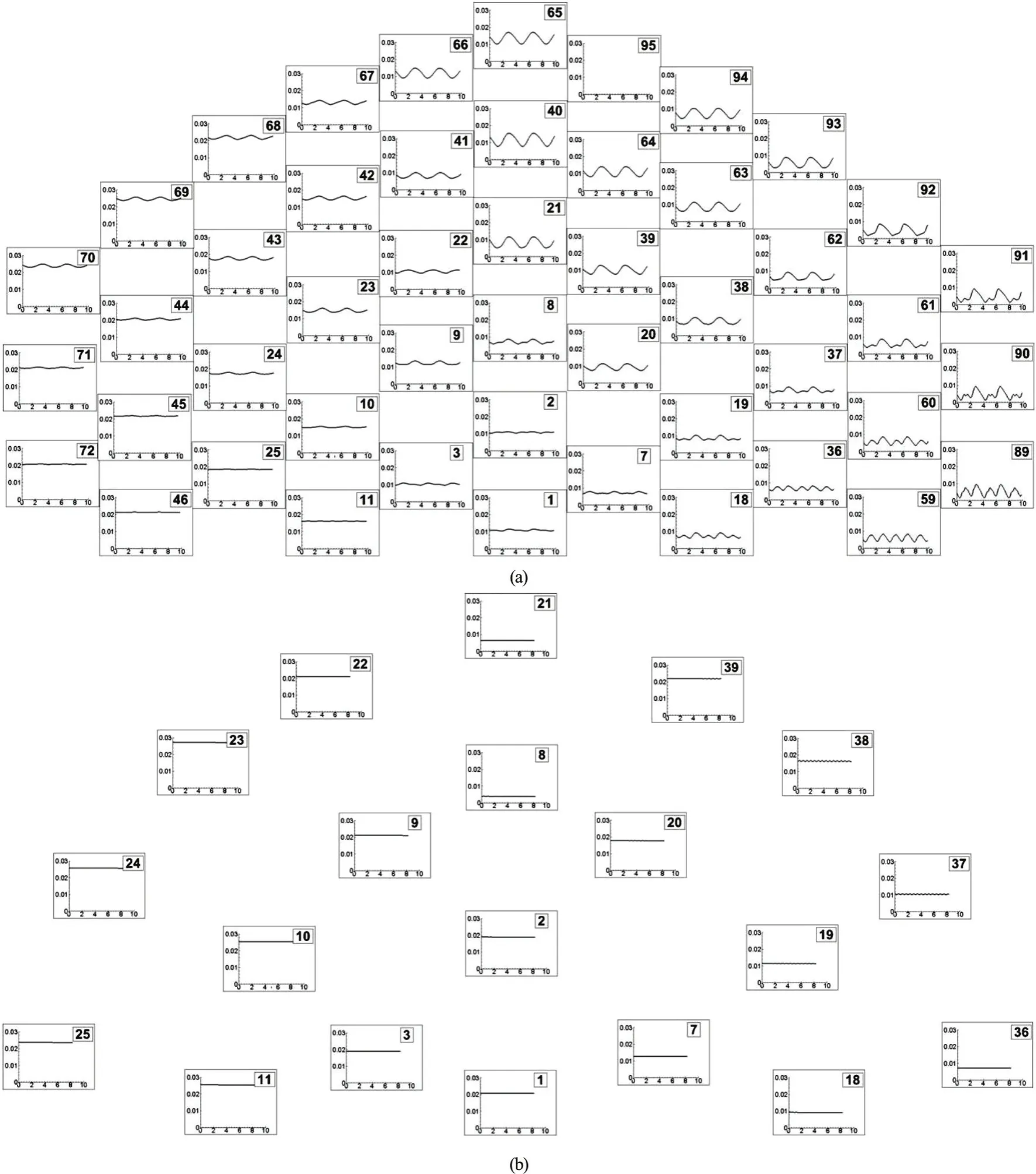
Fig.11 Time history of stream wise drag coefficients for the individual cylinder s, C Dxi, in the array ( R e =2100). Results are shown for the SVF=21.5% Case (a) and SVF=8.8% Case (b) for the cylinders situated in the region with y/ D>0. The number in each frame is the index of the cylinder in the array (see Fig.1)
Figure 10 shows the time history of the global stream wise and span wise drag force coefficients,which were calculated from the summation of the stream wise and, respectively, the span wise (ydirection) forces acting on the solid cylinders within the porous cylinder. One should also mention that the span wise drag force coefficient was referred as the lift force coefficient by Nicolle and Eames[8]. The expressions of the drag coefficients are similar to that given in Eq. (1), but the mean (time-averaged) drag force in the stream wise direction is replaced by the total instantaneous drag force in the stream wise or span wise direction. The time histories of the stream wise drag coefficients in the higher SVF case (SVF=21.5%) display large scale oscillations at the dominant wake frequency (St=0.25). The average of the span wise drag coefficient is equal to zero, which is consistent with the symmetry of the mean flow. This behavior is qualitatively very similar to what is observed for solid cylinders (SVF=100%). Similar to what is observed for solid cylinders, the dominant frequency of the span wise drag coefficient is exactly two times lower than that of the stream wise drag coefficient (SVF=21.5%). This is because of the different effect of alternate shedding of counter rotating wake billows in the wake of the porous cylinder on the total stream wise and span wise drag forces acting on the porous cylinder. In the cases with SVF=8.8% and 15.4%, the amplitude of the unsteady oscillations is negligible (the span wise drag is very close to zero) despite the fact that wake billows are shed at the end of the SSLs. This result is consistent with the 2-D DNS results of Nicolle and Eames[8]who found that the drag force is constant for intermediate SVFs (5%<SVF<15%). The reason for this is that once the distance at which wake billows are successively shed with opposite directions of rotation is sufficiently large, the effect of the billows on the cylinders within the porous patch becomes negligible.Of course, there is shedding behind some of the individual cylinders inside the patch, but these unsteady forces are not sufficient to induce large-scale oscillations of the total force acting on the porous patch. The other trend which is consistent with results in Fig.5(a) is that the total stream wise drag increases monotonically with the SVF.
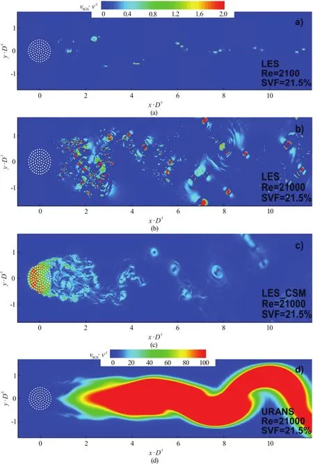
Fig.12 (Color online) Instantaneous nondimensional sub-grid scale viscosity, (νSGS/ν) contou rs for S VF=21 .5%. (a) 2-D LES, Re =2100,(b) 2-D LES, Re =21000, (c) 2-D LES, Re =21000 conducted using a constant Smagorinsky model, (d) The nondimensional eddy viscosity from an unsteady RANS simulation (R e=21000)
As already commented on, for the SVF=21.5%case URANS also predicts the formation of an unsteady wake and correctly captures the main wake frequency (St~ 0.24-0.25). However, the energy associated with the main wake frequency is much smaller in URANS compared to LES (Fig.8). As the billows form at a much larger distance from the porous cylinder in URANS, the unsteady components in the temporal variations of the global stream wise and spanw ise drag force coefficients are very weak compared with LES.In fact,both coefficients are close to constant in URANS (see Fig.10) despite some clear unsteadiness observed in the wake behavior.
Eddy resolving simulations allow an ever more detailed analysis of the effect of the flow on the cylinders, given that the temporal variation of the drag force on the individual cylinders can be calculated.Figure 11(a) presents the temporal variation of the stream wise drag coefficient for the cylinders situated in the region withy/D>0 for the SVF=21.5%case. It gives valuable quantitative information on the cylinders that are subject to large mean forces (e.g.,the ones exposed to the incoming flow) and on the ones that are subject to large unsteady oscillations(e.g., the ones situated in the region defined byx/D>0) and on the dominant frequency of these oscillations. For all cylinders, the dominant frequency of the oscillations corresponds to the shedding frequency behind the porous cylinder (St≈ 0.25).This is true even for the cylinders situated close to the upstream face of the porous cylinder where the unsteady component is relatively weak, especially close to the centerline (y/D=0). Though shedding takes also place in the wake of the individual cylinders,the effect of these oscillations on the temporal variation of the stream wise drag coefficient is negligible. Time series collected in the wake of the cylinders that are shedding show that the dominant nondimensional shedding frequency defined withdis 0.165. This value is close to the one predicted by experiments conducted for isolated cylinders atRed~ 100[8]. Given that the large scale unsteady oscillations are induced by the billows forming behind the cylinder, one expects the amplitude of these oscillations to monotonically decay with the distance from the back of the cylinder. Results in Fig.11(a)confirm this trend. As one moves away from the upstream face of the porous cylinder, the temporal distribution of the drag force on the individual solid cylinders becomes more irregular due to the superposition of upstream-side wakes and to eddies shed from the upstream cylinders that interact with the downstream cylinders in the array. Still, as shown by the velocity power spectrum in the near wake (Fig.14(a)), the only energetic frequencies in the wake correspond to the main shedding frequency of wake billows (St=0.25) and to its double (St≈ 0.25). In other words, the flow in the wake is laminar and unsteady forRe=2100.
Results are also presented in Fig.11(b) for the SVF=8.8% in which the drag force acting on each cylinder in the array is steady. In fact, the flow inside the porous cylinder is practically steady despite the fact that the wake of the porous cylinder is unsteady.As shown in Fig.7(a), the SSLs are so long such that unsteady effects induced by the billows shed at the end of the SSLs on the cylinders forming the array are negligible. This result is also fully consistent with the 2-D DNS of Nicolle and Eames[8]. The ratio of the steady drag force between the cylinders directly exposed to the flow and the cylinders situated at the back of the porous cylinder is close to three. The drag force on the cylinders exposed to the flow in the SVF=8.8% is comparable to the drag force on the corresponding cylinders in the SVF=21.5% case.
3. Discussion
The previous section showed that the accuracy of 2-D LES is similar to that of 2-D DNS simulations of flow past circular porous cylinders performed on finer meshes by Nicolle and Eames[8]forRe=2100. At this relatively low Reynolds number, the flow is not entirely laminar, as also observed from the nondimen sional subgrid-scale eddy viscosity, νSGS/ν, distribution in an instantaneous flow field shown in Fig.12(a)for the SVF=21.5% case. The regions with nonnegligible values of the sub-grid scale viscosity(νSGS/ν > 0.2) roughly correspond to the positions of the wake billows. The maximum values of νSGS/ν in the same flow field are close to 2. In spite of the relatively smooth distribution of the vorticity in Fig.7(c), small-scale velocity fluctuations are developing inside the cores of these vortical structures. Of course,for a given Reynolds number, the Kelvin-Helmholtz instabilities acting on the separated shear layer of the cylinder are weaker for porous cylinders compared to solid cylinders of same diameter. This is because of the bleeding flow. Still, at low Reynolds numbers (e.g.,forRe=2100 corresponding toRed=100), Kelvin-Helmholtz billows develop in the SVF=8.8% case in which the separated shear layers are the longest. Of course, at higher Reynolds numbers, the Kelvin-Helmholtz billows in the separated shear layers of the porous cylinder are strongly coherent and the flow structure is more similar to that observed for solid cylinders at relatively high Reynolds numbers (see Fig.13(b) forRe=21000).
It is in the separated shear layers of the porous cylinder and in the wakes of the solid cylinders situated close to the lateral sides of the porous cylinder that the dynamic Smagorinsky model becomes active and the added dissipation helps keeping the simulation stable on a mesh that is not sufficiently fine for a 2-D DNS simulation. We confirmed this by trying to run a 2-D DNS simulation on the same mesh as the one used for the 2-D LES. The DNS simulation conducted forRe=2100 eve ntual ly diverged . An additional 2-DDNS simulation was performed on a mesh in which the number of grid points was doubled in both directions. This simulation was stable and the distribution of the vorticity in an instantaneous flow field is shown in Fig.13(a). As expected, the wake structure is very similar to the one observed in the corresponding LES simulation in Fig.7(c). More importantly, the mean forces on the individual cylinders predicted by 2-D DNS and 2-D LES performed using the same code are in very good agreement, as shown in Fig.4(c). The value of the global m ean st rea mwise drag coefficientDxGis basically the same in these two simulations. The same very good agreement is observed for the second order statistics. This is exemplified in Fig.15, which shows the comparison between the DNS and LES predictions of the stream wise normal resolved Reynolds stress,
Another important question is whether LES can be used to perform simulations at even higher Reynolds numbers, where the flow is strongly turbulent in the wake and the role of the subgrid scale model is much more important. To investigate this issue, an additional 2-D LES simulation was performed atRe=21000 for the SVF=21.5% case.The mesh was identical to the one used in the LES simulation conducted forRe=2100. The vorticity magnitude distribution in Fig.13(b) confirms that the eddy content of the near wake and of the SSLs of the porous cylinder is much richer compared to the correspondingRe=2100 simulation (see Fig.7(c))and that the near wake region is strongly turbulent atRe=21000. Consistent with this, comparison of velocity power spectra in the near wake in Fig.14 shows that the velocity spectrum is clearly broader in the higher Reynolds number case, especially around the dominant frequency associated with the shedding of wake billow (St=0.25). In fact, in theRe=2100 case the spectrum basically contains energetic frequencies only atSt=0.25 andSt=0.50. As expected, the wider scale of eddies present in the near wake is accompanied by much larger values of νSGS/ν in the instantaneous flow (Fig.12(b)), where the maximum values are close to 20-30. Equally important, the regions with non-negligible values of νSGS/ν are not anymore restricted to the cores of the wake billows. High values of νSGS/ν are also observed in the separated shear layers of the porous cylinder and inside most of the steady wake region.
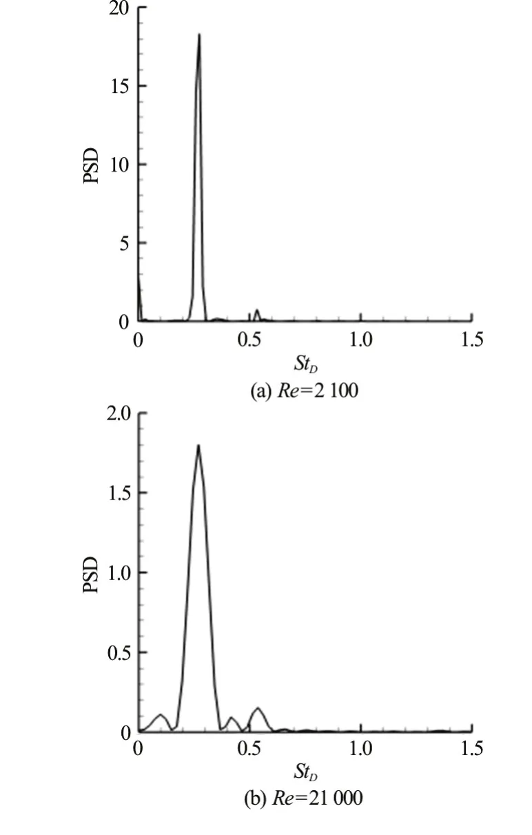
Fig.14 Velocity power spectra in the near wake (x/D~2,SVF=21.5%y/ D~0) predicted by LES for
The fact that a stable 2-D LES solution was obtained on a mesh containing 1500×820 points,means that 3-D LES at similar Reynolds numbers(Re=104-105), where the wake flow is strongly turbulent, is possible using a reasonable amount of computer resources, which is certainly not the case for 3-D DNS. This is important given that at high Reynolds numbers, 3-D vortex stretching is a much more important mechanism compared to the cases analyzed in this paper.
Another important question is the influence of the sub-grid scale model. The base cases were calculated using the dynamic model, which is one of the most non-dissipative sub-grid scale LES models.The dynamic model predicts zero values of the sub-grid scale viscosity in regions where the flow is non-turbulent, even in the presence of mean shear.This is especially important for the type of flow studied in the present work. Results obtained using the constant coefficient Smagorinsky model are also included in Fig.12. As expected, the subgrid-scale viscosity predicted by the later model is larger inside the porous cylinder and the separated shear layers of the porous cylinder. This is simply because these are region of large mean flow shear. The values in the turbulent wake are slightly lower than those predicted by the dynamic model but in both cases the largest values are observed inside the main wake billows. The wake structure is fairly similar in the two simulations(e.g., compare Figs. 13(b), 13(c)). Even more impor-tant for practical applications, the two simulations predict very close values of the integral variables,such as the mean global stream wise drag coefficient(Fig.5).
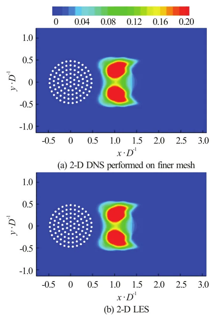
Fig.15 (Color online) Distributions of the stream wise normal Reynolds stress for SVF=21.5%, =2100 Re
On the other hand, unsteady RANS results for the porous case appear to be very far from those predicted by LES and DNS at relatively low (Re=2100) and relatively high (Re=21000) Reynolds numbers. In fact, URANS simulations of flow past porous cylinders appear to be much less successful than URANS simulations of flow past solid cylinders.URANS was found to significantly underestimate the global mean stream wise coefficient and to predict a wake structure that was significantly different than that shown by LES for porous cylinder cases. Despite successfully capturing the dominant wake frequency,RANS predicted much longer separated shear layers and a longer wake, with billows forming at larger distances from the back of the porous cylinder.
The main reason for the failure of URANS to accurately predict this type of flows is the very dissipative character of the RANS approach (e.g.,compare Figs. 12(b)-12(d)) and the fact that large eddy viscosities are automatically predicted in regions of large mean shear. As a result, the natural growth of the instabilities induced by flow past the solid cylinders within the array, as well as the Kelvin-Helmholtz instabilities developing along the separated shear layers of the porous cylinder, are weaker. This is especially true for the bleeding flow region inside the porous cylinder (this is not clearly seen in Fig.12 just because of the different scale used in (d)). Though the separated shear layers contained highly coherent vortex tubes in theRe=21000 RANS simulation,the degree of unsteadiness of the wake was lower compared with theRe=2100 RANS simulation(Figs. 7(d), 12(d)) and, more importantly, compared with theRe=21000 LES simulation. Thus, URANS does not appear to be able to accurately predict flow past porous cylinders. Even the use of a more advanced RANS model (e.g., anisotropic version of thek-ω-SST model) is not expected to result in much more accurate predictions for this type of flows.This is mainly because all these models predict too larger values of the eddy viscosity in regions of large mean shear, which impedes the proper development of the large scale instabilities in the flow.
4. Conclusions
The present study reported results of 2-Deddyresolving simulation of flow past a porous circular cylinder conducted with three different SVFs of 8.8%,15.4% and 21.5%. The flow past the individual rigid cylinders within the patch was resolved. This allowed gaining valuable insight into the main mechanisms determining the temporal evolution of the drag forces on the cylinders and their mean value, as well as the influence of the bleeding flow on the wake-to-cylinder interactions within the porous region and on the wake structure behind the porous cylinder. This information available from simulations that resolve the flow past individual plant stems (rigid cylinders) is relevant to understanding the physics of flow past circular patches of vegetation extending over the full channel depth in open channels, at least away from the solid boundaries.
While the largest drag forces were observed to occur for the cylinders directly exposed to the incoming flow, the largest unsteady oscillations of the drag forces were recorded for the cylinders situated at the back of the porous cylinder. This is because these cylinders are the closest to the wake billows. Though in all three simulations large-scale billows formed because of the interaction between the SSLs, the total drag force was close to steady in the simulations conducted with a sufficiently low SVF (e.g., for SVF=8.8%). In the former cases, the distance at which billows form was larger than three times the diameter of the porous cylinder. The effect of the shedding of billows in the wake of the individual cylinders on the drag forces was found to be relatively small. All the large-scale oscillations in the drag forces were found to occur at the dominant wake frequency corresponding to the shedding of billows behind the porous cylinder. The total time-averaged stream wise drag coefficient acting on the porous cylinder was found to be less than that of a solid cylinder of same diameter. For SVF’s larger than 20%,the predicted stream wise drag coefficient was very close to the value observed for solid cylinders.
The numerical simulations also allowed estimating some of the main parameters that characterize the mean flow past porous cylinders. Following the analysis of Zong and Nepf[7], the variation of the lengths of the steady wake and total wake regions, the level of amplification of the stream wise velocity in the region of flow acceleration on the sides of the porous cylinder and the strength of the bleeding flow at the back of the cylinder were quantified as a function of the SVF.
The fact that results of the present 2-D LES simulations conducted on a Cartesian grid were qualitatively and quantitatively close to 2-D DNS simulations conducted on finer meshes that follow the exact shape of the cylinders’ surface is a very encouraging result. Moreover, 2-D LES were successfully conducted at much higher Reynolds numbers (Re=21000)on the same meshes as the ones used for the base cases (Re=2100). Simulations conducted using 2-D DNS atRe=21000 would have required much finer meshes and smaller time steps.
The differences in the computational resources required to conduct 3-D LES and 3-D DNS at higher Reynolds numbers (Re>10000) will be even larger.The present results, suggest that 3-D LES simulations at moderately high porous cylinder Reynolds numbers(e.g.,Re≈ 10000) are feasible using the approach employed in the present paper. The next step will be to conduct 3-D LES simulations at higher Reynolds numbers where the wake of the porous cylinder is highly turbulent and 3-D effects (e.g., due to vortex stretching) become relatively important.
Acknowledgements
The authors would like to thank the National Center for High Performance Computing (NCHC) in Taiwan and the TRACC facility at the Argonne National Laboratory for providing the computational resources needed to perform the simulations. We also acknowledge the financial support from the Ministry of Science, ICT and Future Planning, subjected to the project EDISON (Education-research Integration through Simulation On the Net, NRF-2011-0020560).
[1] Ricardo A. M., Franca M. J., Ferreira R. M. L. Turbulent flows within random arrays of rigid and emergent cylinders with varying distribution [J].Journal of Hydraulic Engineering, ASCE, 2016, 142(9): 04016022.
[2] Ricardo A. M., Koll K., Franca M. J. et al. The terms of turbulent kinetic energy budget within random arrays of emergent cylinders [J].Water Resources Research,Water Resources Research, 2014, 50(5): 4131-4148.
[3] Salinas-Vazquez M., de la Lama M. A., Vicente W. et al.Large eddy simulation of a flow through circular tube bundle [J].Applied Mathematical Modelling, 2011, 35(9):4393-4406.
[4] Lam K., Li J. Y., So R. M. C. Force coefficient and Strouhal numbers of four cylinders in cross flow [J].Journal of Fluids and Structures, 2003, 18(3): 305-324.
[5] Hassan Y. A., Barsamian H. R. Tube bundle flows with the large eddy simulation technique in curvilinear coordinate [J].International Journal of Heat and Mass Transfer, 2004, 47(14): 3057-3071.
[6] Prasad A., Williamson C. H. K. The instability of the shear layer separating form a bluff body [J].Journal of Fluid Mechanics, 1997, 333: 375-402.
[7] Zong L., Nepf H. Vortex development behind a finite porous obstruction in a channel [J].Journal of Fluid Mechanics, 2012, 691: 1-24.
[8] Nicolle A., Eames I. Numerical study of flow through and around a circular array of cylinder [J].Journal of Fluid Mechanics, 2011, 679: 1-31.
[9] Pierce C. D., Moin P. Progress variable approach for large eddy simulation of large eddy simulation of turbulence combustion [R]. Palo Alto, USA: Stanford University,2001, Report TF-80
[10] Pierce C. D., Moin P. Progress-variable approach for large-eddy simulation of non-premixed turbulent combustion [J].Journal of Fluid Mechanics, 2004, 504: 73-97.
[11] Lilly D. K. A proposed modification of the Germano subgrid scale closure problem [J].Physics of Fluids A, 1992,4(3): 633-635.
[12] Smagorinsky J. General circulation experiments with primitive equations. I: The basic experiment [J].Monthly Weather Review, 1963, 91(3): 99-164.
[13] Chang K., Constantinescu G., Park S. Analysis of the flow and mass transfer processes for the incompressible flow past an open cavity with a laminar and a fully turbulent incoming boundary layer [J].Journal of Fluid Mechanics,2006, 561: 113-145.
[14] Chang K., Constantinescu G. Coherent structures in flow over two-dimensional dunes [J].Water Resources Research, 2013, 49(5): 2446-2460.
[15] Tokyay T., Constantinescu G., Meiburg E. Lock exchange gravity currents with a high volume of release propagating over an array of obstacles [J].Journal of Fluid Mechanics,2011, 672: 570-605.
[16] Chen Z., Ortiz A., Zong L. et al. The wake structure behind a porous obstruction and its implications for deposition near a finite patch of emergent vegetation [J].Water Resources Research, 2012, 48(9): W09517.
[17] Singh S. P., Mittal S. Flow past a cylinder: shear layer instability and drag crisis [J].International Journal for Numerical Methods in Fluids, 2005, 47(1): 75-98.
[18] Park J., Kwon K., Choi H. Numerical solutions of flow past a circular cylinder at Reynolds numbers up to 160 [J].KSME International Journal, 1998, 12(6): 1200-1205.
[19] Sumner D., Price S. J., Paidoussis M. P. Flow-pattern identification for two staggered circular cylinders in cross-flow [J].Journal of Fluid Mechanics, 2000, 411:263-303.
[20] Lee K., Yang K., Yoon D. Flow-induced forces on two circular cylinders in proximity [J].Computers and Fluids,2009, 38(1): 111-120.
[21] Akbari M. H., Price S. J. Numerical investigation of flow patterns for staggered cylinder pairs in cross-flow [J].Journal of Fluids and Structures, 2005, 20(4): 533-554.
- 水動力學研究與進展 B輯的其它文章
- Some notes on numerical simulation and error analyses of the attached turbulent cavitating flow by LES *
- Energy dissipation of slot-type flip buckets *
- Transient aerodynamic characteristics of vans during the accelerated overtaking process *
- Numerical analyses of ventilated cavitation over a 2-D NACA0015 hydrofoil using two turbulence modeling methods *
- Revisit submergence of ice blocks in front of ice cover-an experimental study *
- Couple stress fluid flow in a rotating channel with peristalsis *