
Characteristics of air-water upward intermittent flows with surfactant additive in a pipeline-riser system *
2018-05-14 01:43:02MengchenGao高夢忱JingyuXu許晶禹
水動力學研究與進展 B輯 2018年2期
Meng-chen Gao (高夢忱), Jing-yu Xu (許晶禹)
1. Institute of Mechanics, Chinese Academy of Sciences, Beijing 100190, China
2. School of Engineering Sciences, University of Chinese Academy of Sciences, Beijing 100049, China
Introduction
In the offshore petroleum industry, the pipelineriser system is one of the most fundamental structures in the offshore production, to lift the produced fluids to the platform or the floating production storage and offloading (FPSO) for further processing. In this system, the upward intermittent flow under the endof-field-life conditions can occur when the gas is expanding asa result of the decreased pressure when going up into the riser[1]. The upward intermittent flow can lead to a rapid fluctuation of the pressure and the flow rate to create potential problems in the downstream equipment on the platform.
In recent years, the gas-liquid two-phase flows in a pipeline-rise system attract more and more attention with the development of the offshore oil exploitation in the deep-water area. In experimental studies, two special slugging cases were simulated firstly by Schmidt et al.[2]. Although the range of inclination angles was limited, their work serves as the pioneering work to identify new flow structures and to develop a mathematical model for pipeline-riser slug flows.Following their work, other comprehensive mechanical models were proposed by Taitel[3]and Jansen et al.[4], respectively. In general, these models contain the identification of flow patterns based on different points of view, such as the relationships among the superficial phase velocity, the pressure matching and thein-situgas fraction in the pipeline-riser system.The pressure fluctuation combined with the stability operation criterion was also discussed by Malekzadeh et al.[1], Li et al.[5]and Xing et al.[6]. In fact, the upward intermittent flow will occur in every kind of slugging cycle as a part of liquid production, even as a popular flow pattern for the real industry flow directly once the input gas-liquid ratio is set.
However, in these studies, the impact of the surfactant additive was rarely considered. In practice,in order to increase the output, the produced fluid from the wellbore is mostly mixed in gas-liquid flows with the surfactant additive. Thus, one may see different flow structures under the same inlet conditions.There are two primary reasons in adding the surfactant for increasing the recovery. On one hand, the crude oil liquidity might be enhanced through converting the heavy liquid medium into an easy flow medium. On the other hand, the pressure loss along with the flow direction might be reduced to save the power supplied to the petroleum exploitation. Both reasons could be traced in the fluid property change, thus researchers all over the world show their interest on the surfactant effect on the gas-liquid two-phase flows.
One of the earliest attempts to understand the effect of the surfactant additive on the gas-liquid pipeline flows can be traced back to the work of Greskovich, who used the surfactant additive as a drag reducing agent for an air-water slug flow in horizontal pipes[7]. The results show that the surfactant additive leads to a significant decline of the frictional pressure drop, as large as 40% as compared with the nonsurfactant case. The drag reduction in the gas-liquid flows due to the surfactant additive was also investigated by subsequent researchers[8-14]. Another influence of the surfactant on the two-phase flow is the flow structure. The work of Rozenblit shows that in a vertical flow, the gas bubbles in the air-water solution with the surfactant are smaller in size than those without the surfactant[15]. Lioumbas found that the liquid layer thickness might be affected by the surfactant additive, leading to a significant reduction of the liquid holdup[12]. Based on this feature, the surfactant additive can be used for the gas well de-liquification. In addition, based on the high-speed visualization technology, van Nimwegen investigated the flow morphology of the annular and churn flows as influenced by the surfactant additive[16,17]. The flow patterns might be used to define different flow regimes through Liu’s work, with the surfactant as an additive to the gas-liquid flows in the capillary tubes[18]. In addition, a theoretical attempt was made to explain the turbulence transport in the surfactant solution flow by Gu and Wang[19]. Above studies are good attempts to enhance the knowledge of the gasliquid two phase pipe flows with surfactant additive.
As discussed above, however, in these studies,only one factor is considered, i.e., the upward intermittent flows in a pipeline-rise system without surfactant additive or the effect of the surfactant additive on the normal gas-liquid flows. A review of the past literature shows that no experiment, to the best of the authors’ knowledge, has been reported so far to investigate the upward intermittent flow in a pipeline-rise system with surfactant additive. In addition, most surfactants selected are only suitable for the experimental systems due to their costs and features.Therefore, this paper makes a study of the flow characteristics in the upward intermittent flows using the dodecylbenzene sulfonic acid sodium salt (SDBS)as the surfactant additive. Due to its good applicability in the field application, the SDBS has been already widely used as a friction reducer in industrial oil transport pipes. Thus, this investigation is to extend the knowledge of the flow characteristics of the upward intermittent flows in the pipeline-riser structure. Particular attention is paid to the influence of this kind of surfactant additive on the two-phase flow pattern, the void fraction, the pressure drops and the characteristics in this flow system. As a reference,in each experiment we start with a two-phase flow without surfactant additive before the test of the two-phase flow with surfactant additive.
1. Experimental
1.1 Rheological properties of surfactant solution
As one of the most popular kind of surfactant in the application field, the commercial dodecylbenzene sulfonic acid sodium salt (SDBS) is chosen as the surfactant additive, which is supplied by Sinopharm Chemical Reagent Co., Ltd in China. Besides, according to its good balance between hydrophilic and lipophilic properties, the SDBS in the air-water experimental flows performs similarly to the natural gas and the crude oil in the industrial flows. For better understanding, prior to the flow experiments, the static measurements are carried out to analysis the influence of the surfactant additive on the rheological properties.The samples are prepared by adding small quantities of the surfactant into the tap water with sufficient stirring to prevent the formation of lumps.Thermo Hakke RS6000 rheometer is used to measure the rheological properties of the surfactant solution.The coaxial cylinder rheometer, in which the outer cylinder is fixed and the inner cylinder rotates in a specified rotation rates, might produce secondary flows (Taylor vortex) if not properly handled. Besides,the flow of the fluid between the inner cylinder and the outer cylinder might not be stable during the measurement. The maximum relative error of the measured viscosity is ±0.5% for shear rates ranging from 0.1 s-1to 1000 s-1. Therefore, the flow during the rheology tests might be considered as a laminar flow, and with Z38 DIN and gap width of 2.5 mm, the measurement error can be kept as small as possible.According to industrial cases, the concentration of the surfactant additive is usually less than 1000 mg/L,and Fig.1, which τ represents shear stress and γ represents shear rate, shows the rheograms of the surfactant solution with different concentrations from 0 mg/L to 1000 mg/L at 20°C. Generally, the solutions exhibit the Newtonian fluid behavior, which illustrates that the fluid rheology does not change after the surfactant addition. The apparent viscosity of the surfactant solution ()μ at various concentrations(C) is shown in Fig.2. It can be seen that the apparent viscosity is almost independent of the concentration of the surfactant solution, takes a value between 1.1 mPa?s to 1.2 mPa?s.
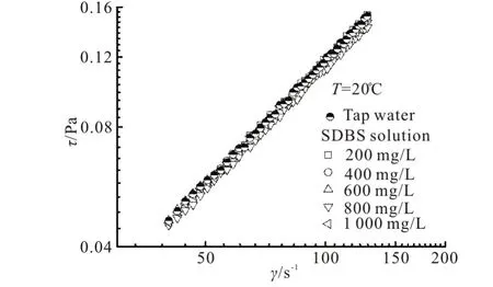
Fig.1 Rheograms of surfactant solutions with different concentrations
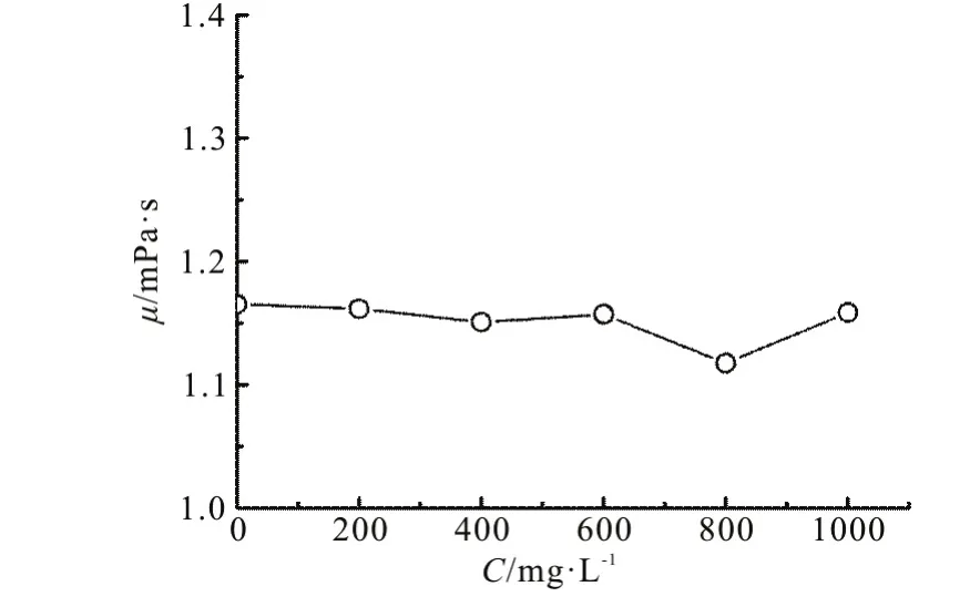
Fig.2 Apparent viscosity of the surfactant solutions vs. concentrations at 20°C
The surfactant tension is measured through the Data-Physics DCAT-11 tensiometer. In Fig.3, the surface tension ()σ is plotted against the concentration of the surfactant solution. An increase of the surfactant concentration up to 200 mg/L leads to a significant decrease of the surface tension, whereas the surface tension thereafter keeps almost a fixed value regardless of the concentration increase. Therefore, the SDBS solutions of concentrations of 200 mg/L and 1000 mg/L are chosen in the following experiments, representing the effect of the surfactant on the upward intermittent flows.
1.2 Experimental set-up and procedure
Experiments are carried out in a circular transparent Perspex pipe of 25 mm in inner diameter. A schematic diagram of the flow loop is shown in Fig.4,whichDrepresents the diameter of the pipe. The test loop consists of a horizontal Perspex pipe of 3.0 m long, connected to a PVC pipe of 2.0 m long, inclined by an angle of 7° from the horizontal plane, followed by a vertical PVC riser of 3.5 m high. The Perspex pipeline and the PVC riser are transparent, allowing visual observation of the flow behavior in the system.A choke with inner diameter of 25 mm is also installed in the facility at the riser top, and the choke is kept fully open during all experiments.
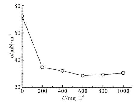
Fig.3 Surface tension of surfactant solutions vs. concentration
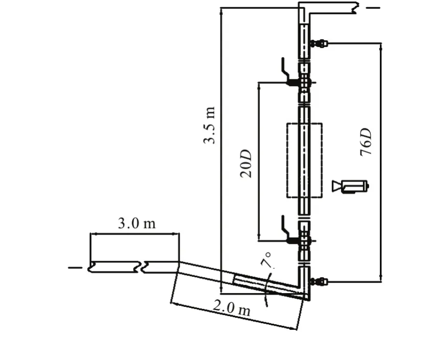
Fig.4 Schematic diagram of test section and measurement scheme of the pipeline-riser system
A gas tank and a regulating valve are used to ensure a constant pressure at the inlet of the gas phase.The air, as the gas phase, is pumped into the pipe via an air compressor. The SDBS solutions are used as the liquid phase, with its properties shown in Table 1.During the experiment, the surfactant additive is put into the water tank with a fixed concentration, and then is fully mixed by a trefoil spiral stirrer. Due to the fact that the surfactant would fail to work properly after several hours, the solution is replaced frequently enough to stabilize the experiment conditions.
A thermal mass flow meter and an electromagnetic flow meter are used to measure the flow rate for the gas phase and the liquid phase, respectively.Experiments are carried out either by keeping the mixture velocity constant and changing the ratio of the gas phase to the liquid phase, or by keeping the super-ficial liquid velocity constant and increasing the superficial gas velocity. The averagein-situgas fraction is measured by two valves that can rapidly closed,which are full opening ball valves with inside diameters equal to the inside diameter of the pipe so that the flow is not disturbed in passing through the open valves[20-22]. As fully developed flows are established, the two valves are closed simultaneously and a sufficient time is taken to ensure the full foam degradation and the liquid phase height accuracy.
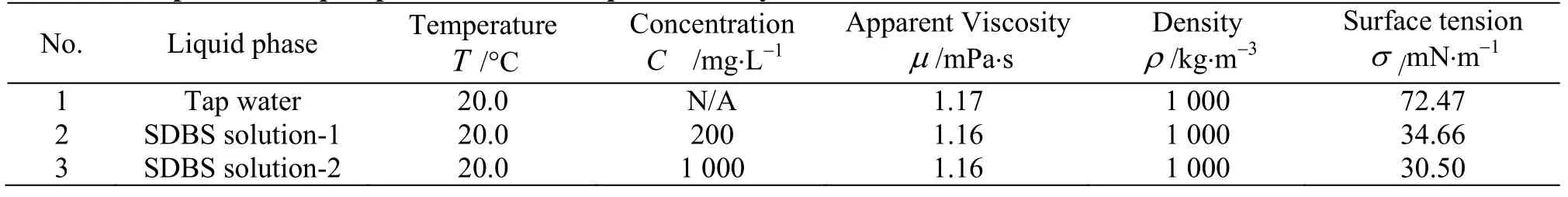
Table 1 Properties of liquid phases used in the present study
For the pressure signal acquisition, two absolute pressure transducers are used to measure the pressure signal in the riser section. The sampling frequency of the pressure signal is 625 Hz, and a total of 62500 samples are collected in the sampling time of 100 s.Hence, accurate results could be obtained from the two transducers located at both ends of the long test section of 76 internal diameters. The flow pattern visualization is conducted by the high-speed camera with parameters as follows: the aperture value F9.0-F11.0, the exposure time 1/2000 s and the ISO 1600.Furthermore, the flow pattern captures, the pressure signal acquisitions, along with the in-situ gas fraction measurements could be carried out simultaneously.
2. Results and discussions
2.1 Flow patterns
When the gas-water mixture passes the declined pipeline, the liquid slug is formed at the bottom of the riser, stopping the gas flow into the riser, which causes gas gathering. Therefore, one sees interfacial turbulence and periodic burst under all operating conditions. It can be speculated that the interfacial shear stress distribution is not uniform, due to the existence of the vortices in the entire fluid layer,which can be seen as one of the most important factor leading to the interface deformation and interfacial waves. Thus, comes the interfacial turbulence near the gas-liquid free interface under different flow rate conditions. Six repeated experiments are conducted under different kinds of inlet conditions and with adopted continuous photography methods lasting for slugging cycles during gas-liquid two phase flows.Thus, in view of reliability, we select photo snaps both on the same position and for a relative fixed time period of gas-liquid flow cycles under each working condition. In Fig.5, the gas core, formed at the center of the tube, tends to be stable due to the increase of the gas flow rate, as the gas-liquid interface becomes much clearer at the same superficial liquid velocity.When the gas phase velocity is low, we see an oscillatory movement due to the amount of gas changes over time. As a result, the wavy interface between the gas and the liquid plays different roles under different conditions. For one example, when the liquid phase velocity is low and the gas phase velocity is high, the gas-liquid interface is irregularly twisted.
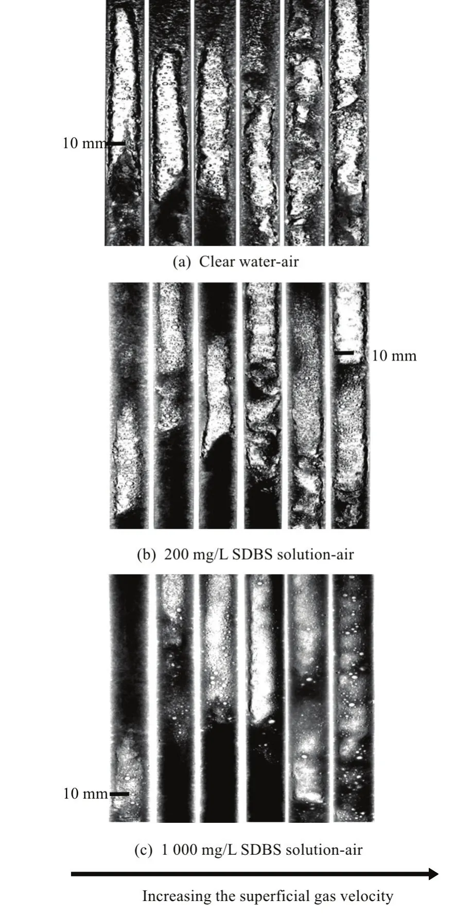
Fig.5 Flow pattern images in the observation section at a constant superficial liquid velocity, vs1=0.71m/s
An additive of surfactant to the liquid causes drastic changes in the distribution of the gas phase inside the liquid, as shown in Fig.5. In the upward intermittent flow, bubbles at the back catch up with those at the front, the continuous collision makes the coalescence and the shape elongation of bubbles.Because the surface tension at the gas-liquid interface is significantly reduced due to the surfactant additive,the size of the dispersed bubbles is greatly reduced and the bubbles become more uniform spheres. In addition, the number of bubbles is in an increasing trend. The visual observation of the slug production shows a periodic injection due to the structure of the pipeline-riser system (Fig.4), and the sizes of the elongated bubbles in the gas/SDBS solution flow are significantly smaller than those in the gas/water flow.
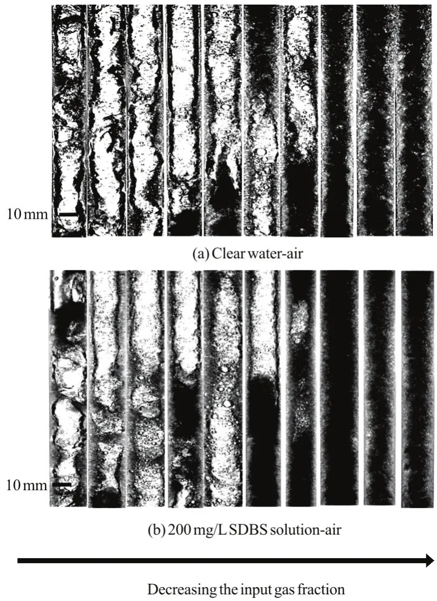
Fig.6 Flow images in the observation section at a constant mixture velocity, vm=1.59m/s
In fact, an additive of surfactant is helpful for the formation of foam flows. When the gas flow rate is low, the energy supported by the gas is not enough for the liquid slug vertical movement. Thus, there is a relatively complex fluctuation at the interface between the two phases. When the flooding wave occurs during the flow process, the stirred liquid not only induces continuously small bubbles into the liquid but also facilitates the mass transfer between the gas and liquid phases. With the addition of surfactant, the disturbance can be reduced effectively, and the interface fluctuation of the gas-liquid presents a more regular appearance. Thus, an additive of surfactant could prevent in part the progress of the big bubble formation and its movement with the liquid phase at a high speed. However, the effect of the surfactant additive on the flow pattern transition is not significant. Figure 6 shows the images of flow patterns by keeping a constant mixture velocity (vm=1.59 m/s)and decreasing the input gas fraction. A comparison between the mixture flow of gas-water and that of gas-SDBS solution shows that in spite of drastic visual changes of the size and the shape of bubbles for all flow patterns, the small difference of the flow pattern transition between the two systems cannot be distinguished clearly. The exception is a little deviation on the transition from the churn to the annular flow. Similar results are also obtained in the studies of Rozenblit et al.[15].
2.2 Average in-situ gas fraction and pressure drop
The averagein-situphase fraction is obtained by the rapid closing valve method, and six repeated experiments are carried out to obtain the mean value and the standard deviation. Figure 7 shows the influence of the surfactant additive on the averagein-situgas fraction (αg) at constant mixture velocities of 1.30 m/s and 1.59 m/s, respectively. Generally, under the same input condition the influence of the surfactant additive on thein-situgas fraction is not significant. More specifically, the influence is negligible when the input gas fraction (βg) is less than 30%. In addition, it can be also found that the large deviations are always found in the range of the input gas fraction between 60% and 80%. Namely, the unstable mixture flows occur during this regime. Furthermore, the addition of surfactant also alleviates the instability of the mixture flow, and the maximum deviation can be decreased from 25% to 10%. In different kinds of mixture velocity cases, the most apparent difference is seen from the maximum value of the averagein-situgas fraction with the input gas fraction from 60%-80% forvm=1.30 m/s rather than with the input gas fraction in the range of 40%-60% forvm=1.59 m/s. It could be seen from the results, the change caused by the surfactant addition in a smaller mixture velocity case is much more significant than in a larger mixture velocity case.
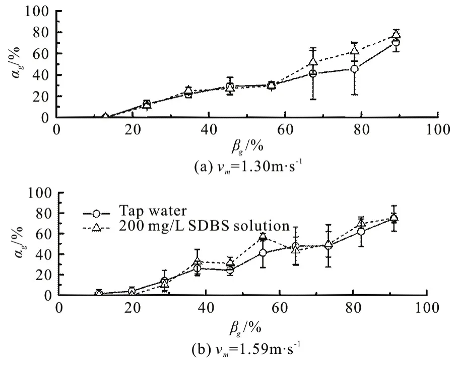
Fig.7 Influence of surfactant additive on the average in-situ gas fraction at constant mixture velocities of 1.30 m/s and 1.59 m/s, respectively
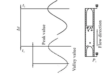
Fig.8 Schematic model of computational method for gas-liquid upward intermittent flow
In the present study, one pressure sensor located at the bottom of the vertical section (P1) is used for measuring the entrance pressure, while another is installed at the riser top (P2). When the mixture fluids flow through the sensors, the pressure is converted to a voltage signal, and recorded by the data acquisition card for the further process. For data processing, the pressure of the upward intermittent flows in a pipeline-riser system can be captured through filtered and transformed voltage signals (Fig.8, in whichtrepresents the time period). Thus, we obtain the pressure amplitude at the bottom of the riser, as shown in Fig.9. At the same superficial liquid velocity, the pressure amplitude increases with the increase of the superficial velocity of the gas phase. Moreover, it is very interesting to find that there is always a turning point in different cases, before which the surfactant additive decreases the pressure amplitude through reducing the surface tension, consistent with the results from the visual observation and thein-situgas fraction measurement (from Figs. 5-7). On the other hand, the pressure amplitude increases with the surfactant additive after that turning point. To explain this phenomenon, there must be a balance between thein-situgas dispersion and the input gas amount. That is to say, for a low gas-liquid ratio, much more small bubbles are formed which can stabilize the flow process obviously, otherwise we have the opposite case.
As can be seen from Fig.9, the pressure amplitude values (p) in the tap water case and the SDBS solution case are similar at the superficial velocities of 0.28 m/s and 1.40 m/s for the liquid (vs1) and gas phases (vsg), respectively. Since the flow pattern changes under different inlet conditions, when the gas velocity reaches the maximum value (1.40 m/s) and the liquid phase velocity keeps small (0.28 m/s), the gas phase dominates the whole flow process. It can be speculated that there is no distinguished difference between two flow cases in which the gas phase is the main phase in both cases even with surfactant additive,because the primary contribution of the pressure loss comes from the liquid gravity terms as shown in Fig.10.
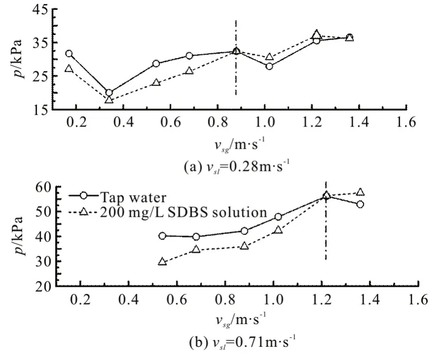
Fig.9 Influence of surfactant additive on pressure amplitude at bottom of riser with constant superficial liquid velocities
Figure 10 shows the total pressure drop (dp/dl)and the frictional pressure drop (dpf/dl) as functions of the input gas fraction for the gas/water flow and the gas/SDBS solution of 200 mg/L, respectively atvm=1.30 m/s. According to previous work, the surfactant addition usually acts as a drag reduction agent for pipeline flows. But there are still some related details to be clarified, such as the influencing range of this additive and the extent that it affects the frictional pressure drop, since the total pressure drop of the riser section includes the gravity pressure drop and the frictional pressure drop. Thus, combined with Fig.7, we calculate the gravity pressure drop from the averagein-situgas fraction values, to obtain the frictional pressure drop through abstracting the gravity pressure drop from the total pressure drop. As can be seen, an addition of surfactant to the two-phase flow reduces slightly the total pressure drop. At a low input gas fraction, the surfactants are less effective for the drag reduction, while the decrease will have more pronounced effects at a high input gas fraction,due to the surfactant influence on the turbulence structures,as similarly observed by Duangprasert et al.[11],Rozenblit et al.[15]. Compared with those in the gas/water flow, the frictional pressure drop might be reduced by increasing the input gas fraction. In the vertical pipe flow, the total pressure drop is dominated by the gravitational part, but as the mixture liquid velocity increases, the frictional component of the pressure drop becomes more important. Combined with Fig.7, under the same input conditions the drag reduction and the increase of the averagein-situgas fraction are relevant to the input gas fraction, the mixture velocity and the SDBS concentration.
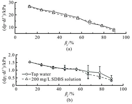
Fig.10 Influence of surfactant additive on two-phase average pressure drop
2.3 Characteristic parameters of upward intermittent flow
The upward intermittent flows in a pipeline-riser system have two most important characteristic parameters in engineering applications, which are the frequency of the liquid slug and the velocity of the liquid slug. In real industrial flow cases, the frequency of the liquid slug determines how often the shock will impact the fixed structure and the downstream devices,meanwhile the mean velocity of the liquid slug represents the yield from the wellbore. From Fig.8,whenNliquid slugs go through the same pressure sensor, there areNpeak values of the pressure signal. Hence, in a unit time (t), the number of peak values is equal to the frequency of the liquid slug(f) as
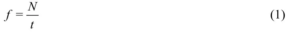
Figure 11 shows the frequency change of the liquid slug against the superficial gas velocity at constant superficial liquid velocities. Here, the visible slugs are counted to check the test results. At a fixed superficial liquid velocity of 0.28 m/s, the frequency increases with the increase of the superficial gas velocity. This is mainly due to the fact that the accumulation time of the gas at the bottom of the vertical pipe is reduced with the increase of the gas volume. In addition, with the increase of the superficial liquid velocity, the effect of the superficial gas velocity on the frequency is gradually weakened. Although the additive of the surfactant reduces the sizes of the elongated bubbles, it does not have a significant impact on the frequency of the liquid slug.
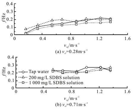
Fig.11 Frequency of liquid slug vs. superficial gas velocity at constant superficial liquid velocities of 0.28 m/s and 0.71 m/s, respectively
Assuming that the head of the liquid slug passing through the upstream sensor to the downstream sensor is Δt, the velocity at the stage of liquid slug (vss)can be expressed as
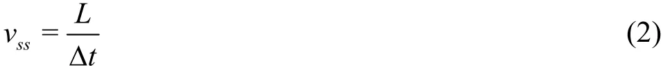
whereLis the distance between the two sensors.The interval time, Δtcan be obtained by the peak values of the pressure signal. Here, the mean velocity of the liquid slug is chosen as a characterization to represent the flow phenomena, though this liquid slug velocity is not constant during the entire flow process.
Figure 12 displays the velocity of the liquid slug vs. the superficial gas velocity at a constant superficial liquid velocity. In general, since the additive of surfactant shortens the length of the elongated bubble and a large number of small bubbles come into the thin film around the elongated bubble, the velocity of the liquid slug in the gas/SDBS solution flow is smaller than that in the gas/water flow. Here, the velocities in the gas/SDBS solution slug flow can be mostly reduced to half of those in the gas/water slug flow. A slight alteration between two kinds of different concentrations of the SDBS solutions may reveal the fact that the time period to establish the same surface tension values are different at different solution concentrations. It is quicker for the SDBS solution-2 to take effect on reducing the surface tension, therefore much smaller bubbles with slower slug velocity are obtained as compared to the SDBS solution-1. However, as mentioned in Section 3.1, the surfactant additive can hardly lead to a transition of flow patterns, thus it acts similarly on the frequency of the liquid slug at different concentrations.
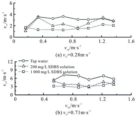
Fig.12 Velocity of liquid slug vs. superficial gas velocity at constant superficial liquid velocities of 0.28 m/s and 0.71 m/s, respectively
As shown in Table 1, an additive of surfactant changes mainly the surface tension, and therefore the Weber number is used to analysis the characteristic parameters of the upward intermittent flow. The Weber number can be defined as
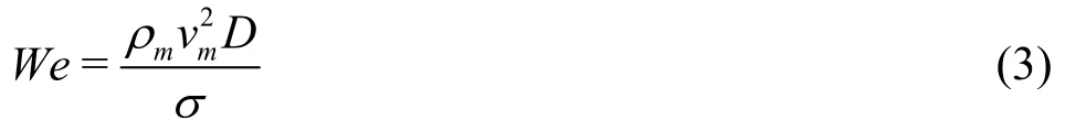
where ρmandvmrefer to the mixture density and the mixture velocity, respectively, andDis the pipe diameter. Figure 13 shows the changes offandvss/vmin the upward intermittent flows with the Weber number at a fixed superficial liquid velocity. It can be found that when the Weber number is low, the frequency of the liquid slug increases steadily and tends to be maintained between 0.1 and 0.2. Interestingly, there is an approximate exponential relationship between the Weber number andvss/vm. Thus,the least squares method is used in identifying the appropriate exponential parameters. An acceptable agreement between the data and the fitting curves can be obtained. This finding might be helpful for predicting the characteristic parameters of the upward intermittent flow by using the Weber number.
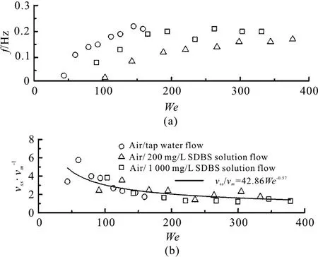
Fig.13 Characteristic parameters of upward intermittent flows vs. Weber numbers at a fixed superficial liquid velocity of 0.28 m/s
3. Conclusions
In this work, the characteristics of upward intermittent flows with surfactant additive in a pipeline-riser system are investigated. The flow patterns of the upward intermittent flows are characterized on the basis of the visual observation and the pressure signals in the riser. It can be found that an additive of surfactant to the carrying liquid causes drastic changes in the distribution of the gas phase inside the liquid, and prevents partly the progress of the big bubble formation in the riser. In addition, owing to the addition of surfactant the sizes of the dispersed bubbles are greatly reduced and the shapes of the bubbles appear to be more uniform spheres. The effect of the surfactant additive on the averagein-situgas fraction and the average pressure drop is weakly distinctive, and the drag reduction is more pronounced at a high superficial gas velocity.
Although the surface tension at the gas-liquid interface shows a significant reduction with the surfactant additive, it does not have a big impact on the frequency of the liquid slug, and its impact is mainly manifested in the velocity of the liquid slug. By the addition of surfactant, the velocity of the liquid slug experiences a nearly 50% reduction from the mixture flow without surfactant additive, approximately independent of the superficial phase velocities. Furthermore, an exponential relationship between the dimensionless velocity of the liquid slug and the Webber number can be obtained when the superficial liquid velocity is fixed.These results might be helpful for estimating the characteristic parameters of the upward intermittent flow by using the input operating conditions.
[1] Malekzadeh R., Henkes R. A. W. M., Mudde R. F. Severe slugging in a long pipeline–riser system: Experiments and predictions [J].International Journal of Multiphase Flow,2012, 46: 9-21.
[2] Schmidt Z., Brill J., Beggs H. Experimental study of severe slugging in a two phase-flow pipeline–riser pipe system [J].Society of Petroleum Engineers Journal, 1980,20(5): 407-414.
[3] Taitel Y. Stability of severe slugging [J].International Journal of Multiphase Flow, 1986, 12(2): 203-217.
[4] Jansen F. E., Shoham O., Taitel Y. The elimination of severe slugging-experiments and modeling [J].International Journal of Multiphase Flow, 1996, 22(6):1055-1072.
[5] Li N., Guo L., Li W. Gas–liquid two-phase flow patterns in a pipeline–riser system with an S-shaped riser [J].International Journal of Multiphase Flow, 2013, 55: 1-10.
[6] Xing L., Yeung H., Shen J. A new flow conditioner for mitigating severe slugging in pipeline/riser system [J].International Journal of Multiphase Flow, 2013, 51:65-72.
[7] Greskovich E. J., Shrier A. L. Pressure drop and holdup in horizontal slug flow [J].AIChEJournal, 1971, 17(5):1214-1219.
[8] Fernandes R. L. J., Jutte B. M., Rodriguez M. G. Drag reduction in horizontal annular two-phase flow [J].International Journal of Multiphase Flow, 2004, 30(9):1051-1069.
[9] Mowla D., Naderi A. Experimental study of drag reduction by a polymeric additive in slug two-phase flow of crude oil and air in horizontal pipes [J].Chemical Engineering Science, 2006, 61(5): 1549-1554.
[10] Wilkens R. J., Thomas D. K. Multiphase drag reduction:Effect of eliminating slugs [J].International Journal of Multiphase Flow, 2007, 33(2): 134-146.
[11] Duangprasert T., Siemanond A. S. K., Wilkes J. O.Vertical two-phase flow regimes and pressure gradients under the influence of SDS surfactant [J].Experimental Thermal and Fluid Science, 2008, 32(3): 808-817.
[12] Lioumbas J. S., Kolimenos C., Paras S. V. Liquid layer characteristics in gas–liquid flow in slightly inclined pipes:Effectof non-ionic surfactant additives [J].Chemical Engineering Science, 2009, 64(24): 5162-5172.
[13] Al-Sarkhi A., Nakla M. E., Ahmed W. H. Friction factor correlations for gas–liquid/liquid–liquid flows with dragreducing polymers in horizontal pipes [J].International Journal of Multiphase Flow, 2011, 37(5): 501-506.
[14] Eshghinejadfard A., Sharma K., Thévenin D. Effect of polymer and fiber additives on pressure drop in a rectangular channel [J].Journal of Hydrodynamics, 2017, 29(5):871-878.
[15] Rozenblit R., Gurevich M., Lengel Y. et al. Flow patterns and heat transfer in vertical upward air–water flow with surfactant [J].International Journal of Multiphase Flow,2006, 32(8): 889-901.
[16] Van Nimwegen A. T., Portela L. M., Henkes R. A. W. M.The effect of surfactants on air–water annular and churn flow in vertical pipes. Part 1: Morphology of the air–water interface [J].International Journal of Multiphase Flow,2015, 71: 133-145.
[17] Van Nimwegen A. T., Portela L. M., Henkes R. A. W. M.The effect of surfactants on air–water annular and churn flow in vertical pipes. Part 2: Liquid holdup and pressure gradient dynamics [J].International Journal of Multiphase Flow, 2015, 71: 146-158.
[18] Abdulbariab H. A., Ming F. L. W., Mahmooda W. K.Insoluble additives for enhancing a blood-like liquid flow in micro-channels [J].Journal of Hydrodynamics, 2017,29(1): 144-153.
[19] Gu W. G., Wang D. Z. Turbulence transport of surfactant solution flow during drag reduction degeneration [J].Journal of Hydrodynamics, 2012, 24(4): 479-487.
[20] Xu J. Y., Wu Y. X., Chang Y. Influence of gas injection on the in-situ oil fraction of an oil-water flow in horizontal pipes [J].Chemical Engineering and Technology, 2009,32(12): 1922-1928.
[21] Jia J., Babatunde A., Wang M. Void fraction measurement of gas-liquid two-phase flow from differential pressure [J].Flow Measurement and Instrumentation, 2015, 41: 75-80.
[22] Olerni C., Jia J., Wang M. Measurement of air distribution and void fraction of an upward air-water flow using electrical resistance tomography and wire-mesh sensor [J].Measurement Science and Technology, 2013, 24(3):035403.
- 水動力學研究與進展 B輯的其它文章
- Some notes on numerical simulation and error analyses of the attached turbulent cavitating flow by LES *
- Energy dissipation of slot-type flip buckets *
- Transient aerodynamic characteristics of vans during the accelerated overtaking process *
- Numerical analyses of ventilated cavitation over a 2-D NACA0015 hydrofoil using two turbulence modeling methods *
- Revisit submergence of ice blocks in front of ice cover-an experimental study *
- 2-D eddy resolving simulations of flow past a circular array of cylindrical plant stems *