
Residual stress determination in friction stir butt welded joints using a digital image correlation-aided slitting technique
2017-11-20 01:56:37YaowuXURuiBAO
CHINESE JOURNAL OF AERONAUTICS 2017年3期
Yaowu XU,Rui BAO
Institute of Solid Mechanics,School of Aeronautic Science and Engineering,Beihang University,Beijing 100083,China
Residual stress determination in friction stir butt welded joints using a digital image correlation-aided slitting technique
Yaowu XU,Rui BAO*
Institute of Solid Mechanics,School of Aeronautic Science and Engineering,Beihang University,Beijing 100083,China
Available online 21 December 2016
*Corresponding author.
E-mail address:rbao@buaa.edu.cn(R.BAO).
Peer review under responsibility of Editorial Committee of CJA.
Production and hosting by Elsevier
http://dx.doi.org/10.1016/j.cja.2016.11.003
1000-9361?2016 Chinese Society of Aeronautics and Astronautics.Production and hosting by Elsevier Ltd.
This is an open access article under the CC BY-NC-ND license(http://creativecommons.org/licenses/by-nc-nd/4.0/).
This paper presents an incremental cutting method for evaluating the longitudinal residual stresses in a butt welded thin plate via combining the traditional residual stress measurement methods and the advanced optical technique.The proposed approach,which can be called digital image correlation(DIC)-aided slitting technique,introduces a successive extension slot to a specimen and employs the DIC technique to measure the released displacement profiles of the cutting sections after each cutting increment.Then the displacement profiles are used to directly calculate the residual stress distributions up to the slot tip and hence,a stress distribution can be obtained after a cutting increment.Finally,all of the stress distributions are averaged to ultimately determine the original residual stress field.This method does not include any complex experimental operations or tedious derivation,and the resolution of stress variation is greatly improved by the continuous measurement of the released displacements.The presented method has been preliminarily verified by a specimen with residual stress introduced by a four-point bending test.The results show that residual stresses determined by the DIC-aided slitting technique agree well with those from finite element(FE)prediction.The residual stress in a friction stir welded aluminum specimen obtained by the presented technique is also consistent with the evaluations given by X-ray diffraction.Furthermore,the residual stresses obtained by the DIC-aided slitting technique demonstrate higher accuracy and stability than the evaluations derived by the DIC-aided contour method.
?2016 Chinese Society of Aeronautics and Astronautics.Production and hosting by Elsevier Ltd.This is an open access article under the CC BY-NC-ND license(http://creativecommons.org/licenses/by-nc-nd/4.0/).
Contour method;
Digital image correlation(DIC);
Friction stir welding;
Residual stresses;
Thin-walled structures
1.Introduction
The application of advanced joining technologies,such as friction stir welding(FSW),1in the fabrication of aircraft structural components is recognized as one of the most promising methods to reduce structure weights and save manufacture costs.2,3However,residual stresses are induced in structures during a welding process and consequently influence the structural integrity assessment.4,5Paulo et al.6,7investigated the effects of FSW residual stresses on the bulking behaviors of aluminum stiffened panels and aluminum plates,respectively.They reported that the collapse loads of the stiffened panels were not influenced by the stress field,but the residual stresses led to a decrease in the compressive strength of the aluminum plates.The effect of FSW residual stresses on fatigue properties was studied by Citarella et al.8using numerical and experimental methods,and the results indicated that the stress fields led to considerable differences in the fatigue crack growth rates.Hence,precise evaluation of residual stresses is important and necessary.The most popular techniques for the measurement of welding residual stresses include diffraction methods and mechanical methods.
Diffraction-based techniques are the most important nondestructive means of determining residual stress distributions,e.g.,the X-ray diffraction method and the neutron diffraction method.Most of the diffraction methods are characterized by high precision and automation compared to mechanical methods.Sutton et al.9examined the residual stresses in 2024-T3 aluminum friction stir butt welds using the neutron diffraction technique,and an asymmetric distribution with respect to the weld centerline was obtained by the three-dimensional residual stress mapping.However,diffraction methods are only available in professional facilities,resulting in huge measurement costs,and they are sensitive to surface conditions or microstructural changes.10
Mechanical methods are mostly destructive and always rely on redistributing the residual stress due to an introduced slot or a small hole that can generate new surfaces and release the original stress field in the object.11The hole-drilling method,the crack compliance method,and the contour method are the most popular destructive methods.There are many advantages for the hole-drilling method,such as accessible necessary equipment and easy operation.Residual stresses in thick aluminum friction stir welded butt joints were measured by Xu et al.12using the hole-drilling method,and the influences of welding parameters on the stress magnitude were analyzed.Nevertheless,the hole-drilling method has a limited spatial resolution,and errors will arise due to localized yielding if residual stresses exceed approximately 50%of the yield.13,14The crack compliance method improves the resolution of the residual stress variation with depth and has the ability to measure both small and very large parts.However,in the first decade of the 21st century,an unknown stress distribution was usually expressed as a series expansion in the inverse solutions,15–17which significantly influenced the accuracy of results and always suffered from non-convergence or fitting problems,18,19making the crack compliance method quite cumbersome to use.Nowadays,Schajer’s20pulse method is routinely used in the inverse solutions for its straightforward conception and concise algebraic operation.In some specific cases especially for laminated composites,the pulse method is necessary because it requires no initial assumption about the continuity of the residual stress distribution.21–24However,the surface gauge in the crack compliance method would eventually respond quite weakly to the release of sub-surface stresses and might result in instability problems.18As a relatively new method for measuring residual stresses,the contour method25is analytically straightforward and simple to apply.From one stress component measurement using the standard contour method to multiple stress components mapping using the multiple-cut contour method26or the multi-axial contour method27,the contour method has got rapid development by Prime and his co-workers in recent years and became increasingly popular.Liu and Yi28and Richter-Trummer et al.29have proven that the contour method could be applied successfully to aluminum friction stir welded plates and reveal the internal residual stresses within the joints.Prime30has also presented advanced applications of the contour method,which is called a two-step process,to determine hoop stresses in cylinders and discontinuities.Moreover,the contour method was combined with the X-ray diffraction method or the holedrilling method by Pagliaro et al.31to measure residual stresses in inaccessible regions using the superposition rule.Nevertheless,the assumption of a flat cut in the contour method is overly restrictive and misleading,which makes error minimization and correction important and necessary.Efforts were made by Prime and Kastengren32for providing an iterative finite element(FE)procedure to reduce errors,but it seemed to be tedious and time-consuming.
Recently,a significant amount of studies have tried to combine the traditional mechanical methods and the advanced optical techniques together to seek a better evaluation for residual stress.Strain gauge elements are usually replaced because the measured volumes in an optical system are continuous displacements but not discrete deformations.Ponslet and Steinzig33exploited an electronic speckle pattern interferometer system to improve the results of strain gage hole-drilling.Schajer et al.34presented a full-field,multi-axial computation technique for determining residual stresses using the holedrilling method with the digital image correlation(DIC)technique.Moreover,residual stresses across interfaces at macroand micro-scales were measured by Blair et al.35using slitting and DIC,while Winiarski et al.36also mapped residual stress distributions at micro-scale in amorphous materials via the DIC technique.
In this work,the ideas of the crack compliance method and the contour method are considered.A technique characterized by sequential cutting and multiple inverse solutions as well as displacement measurements in each cutting step using the DIC technique,is presented to provide more accurate and reliable assessment for residual stresses in a welded thin plate.Considering that the transverse(perpendicular to weld)residual stresses are usually much smaller than those in the longitudinal direction(parallel to weld)in welded joints,only the longitudinal residual stresses are taken into account in this paper.Furthermore,the proposed DIC-aided slitting technique is analytically simple and easy to implement.
2.Methods and procedure
2.1.Concept
Based on the linear elastic superposition principle,the released displacements of the newly generated surface caused by an introduced slot can be used to determine the corresponding released stresses,i.e.,σ=f(u),whereumeans the measured displacements and σ represents the original residual stresses.The idea is that if a specimen is sequentially cut into two parts,the released displacement profile after each cutting increment can be measured to calculate the original stress distribution up to the slot tip,as shown in Figs.1 and 2.Therefore,until the specimen is split into two parts,residual stresses in[0,a1]are evaluated for three times,and those in[a1,a2]are evaluated twice,whereas those in[a2,B]are evaluated only once,wherean(n=1,2,...)means the cut depth andBrepresents the specimen width.Then the evaluations for the same sections can be averaged to obtain a more accurate and reliable assessment.The procedure of the presented method to determine the residual stress distribution from the released displacement profile involves three steps which are shown in Fig.3.In the first step,one should note that it is unlikely to directly measure the deformations on the newly generated surface before the specimen is completely broken in two.Therefore,the displacement profile of the slot edge is measured during the cutting process.Details are presented in the following sections.
Compared to the crack compliance method and the contour method,the DIC-aided slitting technique has the following advantages:(1)stability.In the crack compliance method,the strain gauge is located at a pre-existing surface and could respond weakly to the releases of sub-surface stresses and make the inverse unstable,but in the DIC-aided slitting technique,the released displacement of the slot edge is directly measured to characterize the deformation of the cutting surface and there will be no instability problem;(2)accuracy.The displacement contour is mapped to determine the residual stress distribution in the contour method,and the entire test data are obtained from the final cross section after the specimen is split into two parts based on the flat cut assumption.Finally,the residual stresses are evaluated only once and there might be considerable noise introduced by the inaccuracy of the measurement or the simplified assumption.In the DIC-aided slitting technique,however,the specimen is sequentially cut and the displacement profile at each step is recorded by the DIC technique to calculate the residual stress distribution up to the slot tip.Therefore,the original residual stresses are evaluated for many times during the cutting process,and a more accurate and reliable evaluation is possible if all the obtained stress distributions are rationally utilized,e.g.,an arithmetic average is applied to the technique presented in this paper.
2.2.Theory
The pulse method is used here in the inverse solutions for residual stresses on account of its simplicity and convenience,but there are some differences from that used in the crack compliance method.A brief description of this method is presented below.
In the pulse method,the residual stress and released displacement fields are discretized to a series of discrete values,as shown in Fig.4 and the following equations20,37:
where σjrepresents the stress value in thejth interval and remains unchanged at different cut depths,uj(a)corresponds to the released displacement value in thejth interval and varies with different cut depthsa,Uj(x)is the pulse function,andmis the total number of intervals and also varies with different cut depths.
The pulse functions are defined as follows:
Assuming a linear elastic deformation,the measured displacements corresponding to the released residual stresses given by Eq.(1)become
The elementDij(a)in matrixD(a)represents the measured displacement in theith interval caused by the release of a unit tension stress in thejth interval,i.e.,
D(a)is a displacement matrix due to the releases of unit stresses,which is also called a displacement calibration coefficients matrix and can be easily determined by FE calculations.Therefore,
whereSis the inverse matrix ofD,i.e.,the stress calibration coefficients matrix.
Note that the displacement calibration coefficients matrixDis different from the compliance matrixCin the crack compliance method which also uses the pulse method in the inverse solutions.The compliance matrix is about strain coefficients and the corresponding inverse formula isC·σ = ε,where ε represents the measured strains of a certain position and changes with the extension of the slot.An error is accumulated in each solution step because residual stresses are calculated in a stepby-step manner.18This defect will not occur to the DIC-aided slitting technique because at each cut depth,the displacement profile of the slot edge is measured and the stress distribution up to the slot tip can be determined.Calculations are completed in one step and errors will not be accumulated.
To make full use of the displacement field information during the cutting process,the specimen is sequentially cut and the displacement profiles are recorded at each cut depth.Prior to this,the corresponding displacement calibration coefficients matrices of the specimen for different cut depths are given by FE analysis.Therefore,the residual stress distributions of all the cutting sections can be obtained at each step by Eq.(5)using released displacements and displacement calibration coefficients matrices.Finally,a highly accurate and reliable residual stress evaluation can be found by an algebraic average based on the previous groups of stress evaluations.
2.3.FE simulation
An FE simulation was used here to demonstrate the operation of the DIC-aided slitting technique.The original model was assumed to be a 50 mm×200 mm rectangular plate containing a self-balanced longitudinal welding residual stress expressed by the following equation:where σyis the original longitudinal residual stress parallel to the weld line,σ0is the maximum tensile residual stress,fis defined as the half-width of the tensile stress zone,andxrepresents the distance from the specimen edge.We set σ0=200 MPa andf=10 mm.
Taking into account the symmetrical characteristic of the structure,a 2D one-half model was built using the ANSYS commercial FE code and a 50×100 mesh of high-order 8-node quadrilateral plane stress elements(PLANE183).The material behavior was isotropic linear elastic with a Young’s modulus of 78.3 GPa and a Poisson’s ratio of 0.33.The residual stresses were initialized by the built command‘INISTATE”,and the first step involved ensuring that it was self-balanced.The second step involved removing the elements gradually with the command ‘EKILL” to simulate the sequential cutting.Then,the released displacement profile at each cut depth due to the release of the residual stress could be obtained.Meanwhile,a unit tension stress was applied at different locations of the same FE model(with the same killed elements and no residual stress)and the displacements of the slot edge were extracted to make up the different columns in the corresponding matrixD(a).Combined with Eq.(5),the residual stress distribution up to the slot tip at each cut depth could be directly calculated.
To keep things simple,only the specimen with a cut depth of 30 mm is presented here.The killed elements in the meshed FE model are shown in Fig.5(a)and the measurement of the released displacement profileu(30)is shown in Fig.5(b).The interval length was designated as 1 mm and henceDis a 30×30 matrix.A unit tension stress was applied at the seventh interval and the displacements extracted from the slot edge were exactly the seventh column,i.e.,D7j(1≤j≤30)in matrixD(30),as shown in Fig.5(c).
The measured displacement profileu(30)and the seventh column of matrixD(30)are shown in Fig.6(a)and(b),the subsequently obtained residual stress distribution for the cutting section by the inverse solution is shown in Fig.6(c).
3.Experiment
3.1.Experimental validation by a four-point bending beam
A specimen containing residual stress introduced by a fourpoint bending test was prepared to demonstrate the validity and superiority of the presented technique.The specimen was a plate made of aluminum alloy 2024-T351 with a cross section measuring 10 mm×40 mm and a length of 300 mm.The four-point bending fixture was arranged so that the outer contact pins were 260 mm apart and the inner ones were 120 mm apart,as shown in Fig.7.The specimen was slowly loaded to a maximum load of 34 kN.
The material constants used here in the bilinear model were obtained by static tensile tests,where Young’s modulusE=78.3 GPa,plastic modulusE′=6 GPa,and yield stress σs=291 MPa.This model was subsequently used in an elasto-plastic FE simulation of the four-point bending process to obtain the expected residual stress distribution throughout the width of the specimen.
During the bending process,the longitudinal strain in the central part of the specimen was measured.The data were shown to be highly consistent with the analytical results from FE simulation and the deviation of the maximum value was less than 5%,which convinced us that the residual stress profile derived by FE simulation could be a characterization of the actual stress distribution.Subsequently,the residual stress of this specimen was measured using the presented technique and the results were compared to the evaluations by FE simulation.The residual stress measurement arrangement is shown in Fig.8.
Firstly,two sides of the specimen were fixed firmly to avoid the rigid-body translation and rotation during the experiment.Secondly,the first set of pictures of the observed zones along the cutting line was recorded as the reference pictures,as with pictures 1–5 in Fig.9(a).Then,the sequential cutting was performed by an electric saw and the slot extension was divided into six stages,i.e.,15,20,25,30,35,and 40 mm,until the specimen was completely split into two parts.Pictures containing the slot taken after each increment were used as target pictures,as with pictures1′–3′in Fig.9(b).Finally,the displacement profiles were obtained by digital matching between the reference pictures and the target pictures via Vic-2D business software.
The displacement profiles were not mapped on the cross section,but from the pictures of the observed zones containing the slot,which made it possible for multiple measurements before the specimen was split into two.The displacement profiles were extracted on the line 1 mm from the slot edge to reduce the error due to the plastic deformations on the cutting surface induced by the physical separation,as shown in Fig.9(c).Accordingly,the coefficients in matrixDwere calculated on the corresponding positions.
3.2.Residual stress determination in a friction stir welded joint
The residual stress of a flat butt welding was measured using the DIC-aided slitting technique and X-ray diffraction.The specimen was a rolled 2024-T351 aluminum plate with a central weld created by the friction stir welding technique.The tool used in this work had a 12 mm diameter shoulder,and the measured process parameters were a rotation rate of 600 r/min and a traverse speed of 100 mm/min.The sketch of the specimen was similar to that in Fig.1,with a dimension of 120 mm×240 mm and a thickness of 5 mm.The material models and experimental procedure for measuring residual stresses were approximately the same as those of the fourpoint bending specimen.Moreover,the slot extension was divided into four stages,i.e.,90,100,110,and 120 mm.
4.Results and discussion
4.1.Residual stress in the four-point bending beam
The measured displacement profiles at each step are shown in Fig.10.
The scatters represent the displacements measured by the DIC technique,and the solid lines are the smoothed values of the discrete data.From Eq.(5),we learn that the stress calibration coefficients matrixSwill magnify any noise generated throughout the experiment.To reduce the measurement noise and for the convenience of further analyses,the discrete displacements were smoothed by polynomial least squares f i t-ting and then the smoothed values were substituted into Eq.(5)to calculate the residual stresses for different cut depths.Both calculated results and FE predictions are shown in Fig.11.
The trend of the calculated residual stress distribution displays correctly,and small deviations in the magnitude appear where the stress distribution changes direction when compared to the predicted results from the FE simulation.The differences arise partially from the measured data and partially from the simplified material model used in the FE analysis.We can also see that most of the last points in the inverse data deviate far from the predicted results,which can be analytically determined as incorrect.The main reason was the discrepancy between the FE model and the actual configuration in the vicinity of the slot tip,which made the solutions of the last points unstable.Therefore,all of the last data points were excluded.
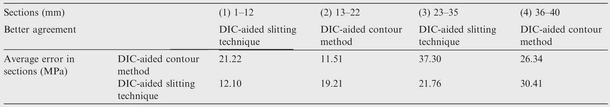
Table 1 Absolute errors in different sections of the DIC-aided slitting technique and the DIC-aided contour method.
It was observed that residual stresses in[0,15]mm were evaluated for six times,those in[15,20]mm were evaluated for five times,and by the analogy,those in[35,40]mm were evaluated only once.Finally,the residual stress distributions for different cut depths were arithmetically averaged to ultimately determine the original residual stress.Moreover,the displacement profile measured after the specimen was split into two parts,i.e.,the one in Fig.10(f),was used to evaluate the residual stress via the idea of the contour method.In fact,the contour method used here should be called a DIC-aided contour method because there were some differences in the measurements of displacements between the DIC-aided contour method and the standard contour method presented by Prime25Electrical discharge machining was employed to cut the specimen in the standard contour method and then a coordinate measuring machine was used to map a 2D contour from the cutting surface.While in the DIC-aided contour method,a cut was made by an electric saw and a 1D displacement profile of the slot edge was obtained by the DIC technique to characterize the deformation of the cutting surface.However,the inverse solutions of the residual stresses were the same as those of the standard contour method,i.e.,applying the opposite of the measured displacements as boundary conditions to the FE model,then the residual stresses were obtained.Residual stresses evaluated from the DIC-aided slitting technique and the DIC-aided contour method are shown in Fig.12.The reason for using the DIC-aided contour method,instead of the standard contour method,to make a comparison was that superiorities of the DIC-aided slitting technique could be obviously demonstrated only if the residual stress was evaluated based on the same displacements.
In general,both results coincided relatively well with the FE prediction in most areas.Therefore,the total range was divided into four sections according to the magnitude of the absolute errors in both methods,as shown in Fig.12.The absolute error due to each scatter relative to the FE evaluation was calculated and averaged in each section,which is shown in Table 1.
From the perspective of error magnitude,the evaluations of the DIC-aided slitting technique in Sections(1)and(3)had a smaller error than those obtained by the DIC-aided contour method,and they together shared a proportion of 62.5%of the total range(Sections(1)–(4).In the rest of areas,the DIC-aided contour method was better and occupied a proportion of 37.5%.From the perspective of average error in each section,the DIC-aided slitting technique seemed more stable due to a smaller fluctuation,which could be a characterization of its reliability.Hence,whether considering the error’s magnitude or the stability of the evaluations,the DIC-aided slitting technique was superior to the DIC-aided contour method and could be explained as follows:in the DIC-aided contour method,stresses were evaluated only once from the displacement profile after the specimen was split into two,while in the DIC-aided slitting technique,the displacement information during the cutting process was recorded and residual stresses in most regions were evaluated for many times,and then the arithmetic average of the evaluations consequently yielded a more accurate and reliable result.However,the observed area in the DIC measurements was limited to the surface of the specimen and the internal residual stress distribution remained unknown.
4.2.Residual stress in the friction stir welded specimen
The displacement profiles of the friction stir welded specimen at different cut depths are shown in Fig.13,accompanied by the values smoothed using the multi-peak fitting of Lorentzian functions.
The smoothed data were substituted into Eq.(5)to calculate the residual stress distribution at each cut depth,and the ultimate residual stress distribution was obtained with further averaging.Evaluations obtained by the DIC-aided slitting technique and the DIC-aided contour method are presented in Fig.14.Both evaluations were compared to the data given by the X-ray diffraction technique.
All of the residual stresses in the three cases exhibited a double-peak distribution.The maximum tensile residual stresses were located at 5–6 mm away from the weld center,approaching the boundary of the heat affected zones.However,the residual stress profile of the FSW was not completely symmetrical about the weld centerline.In each distribution presented above,the peak value on the left side of the weld was larger than that on the right side,which appeared reasonable because of the different forming processes on the advancing side and the retreating side.1,38
The residual stresses measured by the DIC-aided slitting technique were in good agreement with those measured using X-ray diffraction,which indicated the practicability of the technique for evaluating residual stresses in welded joints.The slight differences in magnitude arise partially from the measured deformations and partially from the material constants used in the FE analyses.Moreover,although the evaluations obtained by the DIC-aided contour method were modelled correctly in trends and magnitudes,errors relative to the evaluations given by X-ray diffraction were larger than those of the presented DIC-aided technique except for a few points,as shown in Fig.14.The main reason was that the residual stresses within and around the weld were evaluated for four times in the DIC-aided slitting technique.This observation further demonstrated the superiority of the DIC-aided slitting technique.
Although the X-ray diffraction method was recognized as a surface technique because of its low penetration ability,the residual stresses obtained by X-ray diffraction were regarded as the reference stresses here.The reason was that in this study,the measurement of the released displacements in the DIC-aided slitting technique or the DIC-aided contour method was limited to the surface and therefore,the stresses of the specimen top surface were obtained.In fact,the variations of residual stresses through the thickness in a thin welded plate were usually small and could be neglected in most cases.
5.Conclusions
This paper presented a DIC-aided slitting technique for evaluating residual stresses in weld joints using sequential cutting and multiple inverse solutions based on linear elastic models.This technique was verified by a four-point bending specimen and a friction stir welded specimen,and the following conclusions were obtained:
(1)Residual stresses of the four-point bending specimen evaluated by the DIC-aided slitting technique agreed well with those from the FE prediction.Compared to the DIC-aided contour method,the DIC-aided slitting technique had better accuracy and stability.
(2)Residual stresses in the FSW joint determined by the DIC-aided slitting technique were consistent with the evaluations obtained by X-ray diffraction.Meanwhile,the DIC-aided slitting technique would be a powerful means for measuring longitudinal residual stresses in a butt welded thin plate.
(3)Until the specimen was split into two parts,displacement profiles at each cut depth were recorded during the cutting process and residual stresses in most regions were evaluated for many times.These operations made the ultimate result which was obtained by the arithmetic average of the previous evaluations more accurate and reliable.
Acknowledgement
This study was supported by the National Natural Science Foundation of China(No.11272029).
1.Mishra RS,Ma ZY.Friction stir welding and processing.Mater Sci Eng R:Rep2005;50(1):1–78.
2.Zhan M,Guo K,Yang H.Advances and trends in plastic forming technologies for welded tubes.Chin J Aeronaut2015;29(2):305–15.
3.Servetti G,Zhang X.Predicting fatigue crack growth rate in a welded butt joint:The role of effectiveRratio in accounting for residual stress effect.Eng Fract Mech2009;76(11):1589–602.
4.John R,Jata KV,Sadananda K.Residual stress effects on nearthreshold fatigue crack growth in friction stir welds in aerospace alloys.Int J Fatigue2003;25(9):939–48.
5.Jeyakumar M,Christopher T.Influence of residual stresses on failure pressure of cylindrical pressure vessels.Chin J Aeronaut2013;26(6):1415–21.
6.Paulo R,Carlone P,Valente R,Teixeira-Dias F,Palazzo G.Influence of friction stir welding residual stresses on the mechanical behaviour of aluminium stiffened panels.2nd ECCOMAS young investigators conference;2013 September 16;Bordeaux,France.
7.Paulo RMF,Carlone P,Valente RAF,Teixeira-Dias F,Palazzo GS.Influence of friction stir welding residual stresses on the compressive strength of aluminium alloy plates.Thin-Wall Struct2014;74:184–90.
8.Citarella R,Carlone P,Lepore M,Palazzo GS.Numericalexperimental crack growth analysis in AA2024-T3 FSWed butt joints.Adv Eng Softw2015;80:47–57.
9.Sutton MA,Reynolds AP,Wang DQ,Hubbard CR.A study of residual stresses and microstructure in 2024-T3 aluminum friction stir butt welds.J Eng Mater Technol2002;124(2):215–21.
10.Ganguly S,Fitzpatrick ME,Edwards L.Use of neutron and synchrotron X-ray diffraction for evaluation of residual stresses in a 2024-T351 aluminum alloy variable-polarity plasma-arc weld.Metall Mater Trans A2006;37(2):411–20.
11.Withers PJ.Residual stress and its role in failure.Rep Prog Phys2007;70(12):2211–64.
12.XuW,LiuJ,ZhuH.Analysis of residual stresses in thick aluminum friction stir welded butt joints.Mater Des2011;32(4):2000–5.
13.Withers PJ,Bhadeshia H.Residual stress.Part 1–Measurement techniques.Mater Sci Technol2001;17(4):355–65.
14.ASTM.Standard test method for determining residual stresses by the hole-drilling strain-gage method.West Conshohocken(PA):American Society for Testing Materials;2013.Report No:ASTM E837-13a.
15.Lee MJ,Hill MR.Intralaboratory repeatability of residual stress determined by the slitting method.Exp Mech2007;47(6):745–52.
16.Urriolagoitia-Sosa G,Durodola JF,Fellows NA.Effect of strain hardening on residual stress distribution in beams determined using the crack compliance method.J Strain Anal Eng Des2007;42(2):115–21.
17.Nowell D,Tochilin S,Hills DA.Measurement of residual stresses in beams and plates using the crack compliance technique.J Strain Anal Eng Des2000;35(4):277–85.
18.Prime MB.Residual stress measurement by successive extension of a slot:the crack compliance method.Appl Mech Rev1999;52(2):75–96.
19.Prime MB,Hill MR.Uncertainty,model error,and order selection for series-expanded,residual-stress inverse solutions.J Eng Mater Technol2006;128(2):175–85.
20.Schajer GS,Prime MB.Use of inverse solutions for residual stress measurements.J Eng Mater Technol2006;128(3):375–82.
21.Schajer GS,An Y.Residual stress determination using crossslitting and dual-axis ESPI.Exp Mech2010;50(2):169–77.
22.Shokrieh MM,Akbari S,Daneshvar A.A comparison between the slitting method and the classical lamination theory in determination of macro-residual stresses in laminated composites.Compos Struct2013;96:708–15.
23.Akbari S,Taheri-Behrooz F,Shokrieh MM.Slitting measurement of residual hoop stresses through the wall-thickness of a f i lament wound composite ring.Exp Mech2013;53(9):1509–18.
24.Shokrieh MM,Akbari S.Isolation of residual shear stress effects in slitting measurement of residual normal stress in laminated composites.J Compos Mater2014;48(7):791–8.
25.Prime MB,Gonzales AR.The contour method:simple 2-D mapping of residual stresses.In:Webster GA,editor.Sixth international conference on residual stresses.ICRS-6:Proceedings of the 6th International Conference on Residual Stresses;2000 July 10–12.Oxford,UK.London:Maney Publishing;2000.p.617–24.
26.Pagliaro P,Prime MB,Swenson H,Zuccarello B.Measuring multiple residual-stress components using the contour method and multiple cuts.Exp Mech2010;50(2):187–94.
27.DeWald AT,Hill MR.Multi-axial contour method for mapping residual stresses in continuously processed bodies.Exp Mech2006;46(4):473–90.
28.Liu C,Yi X.Residual stress measurement on AA6061-T6 aluminum alloy friction stir butt welds using contour method.Mater Des2013;46:366–71.
29.Richter-Trummer V,Moreira PMGP,Ribeiro J,de Castro PMST.The contour method for residual stress determination applied to an AA6082-T6 friction stir butt weld.In:Scardi P,Ricardo CLA,editors.Materials science forum.ECRS 8:proceedings of the 8th European conference on residual stresses;2010 June 26–28;Trento,Italy.Stafa-Zurich:Trans Tech Publications Ltd;2011.
30.Prime MB.Contour method advanced applications:hoop stresses in cylinders and discontinuities.In:Proulx T,editor.Engineering applications of residual stress.Proceedings of the 2011 annual conference on experimental and applied mechanics;2011 June 13–16;Uncasville,USA,vol.8.New York:Springer;2011.p.13–28.
31.Pagliaro P,Prime MB,Robinson JS,Clausen B,Swenson H,Steinzig M,et al.Measuring inaccessible residual stresses using multiple methods and superposition.ExpMech2011;51(7):1123–34.
32.Prime MB,Kastengren AL.The contour method cutting assumption:error minimization and correction.In:Proulx T,editor.Experimental and applied mechanics.Proceedings of the 2010 annual conference on experimental and applied mechanics;2010 June 7–10;Indianapolis,USA,vol.6.New York:Springer;2011.p.233–550.
33.Ponslet E,Steinzig M.Residual stress measurement using the hole drilling method and laser speckle interferometry.Part II:Analysis technique.Exp Tech2003;27(4):17–21.
34.Schajer GS,Winiarski B,Withers PJ.Hole-drilling residual stress measurement with artifact correction using full-field DIC.In:Ventura CE,Crone WC,Furlong C,editors.Experimental and applied mechanics.Proceedings of the 2012 annual conference on experimental and applied mechanics;2012 June 11–14;Costa Mesa,California,vol.4.New York:Springer;2013.p.403–14.
35.Blair A,Daynes N,Hamilton D,Horne G,Heard PJ,Hodgson DZL,et al.Residual stress relaxation measurements across interfaces at macro-and micro-scales using slitting and DIC.J Phys:Conf Ser2009;181(1):012078.
36.Winiarski B,Langford RM,Tian J,Yokoyama Y,Liaw PK,WithersPJ.Mapping residual stress distributions at the micron scale in amorphous materials.Metall Mater TransA2010;41(7):1743–51.
37.Schajer GS.Measurement of non-uniform residual stresses using the hole-drilling method.Part I—Stress calculation procedures.J Eng Mater Technol1988;110(4):338–43.
38.Staron P,Kocak M,Williams S,Wescott A.Residual stress in friction stir-welded Al sheets.Physica B2004;350(1):E491–3.
12 June 2016;revised 26 July 2016;accepted 25 August 2016
 CHINESE JOURNAL OF AERONAUTICS2017年3期
- CHINESE JOURNAL OF AERONAUTICS的其它文章
- Improving the process forming limit considering forming defects in the transitional region in local loading forming of Ti-alloy rib-web components
- A cost driven predictive maintenance policy for structural airframe maintenance
- Analysis of the current density characteristics in through-mask electrochemical micromachining(TMEMM)for fabrication of micro-hole arrays on invar alloy film
- Beam-pointing error compensation method of phased array radar seeker with phantom-bit technology
- Estimation of ballistic coefficients of space debris using the ratios between different objects
- A rapid compensation method for launch data of long-range rockets under influence of the Earth’s disturbing gravity field