
Decentralized adaptive sliding mode control of a space robot actuated by control moment gyroscopes
2016-11-23 06:11:50JiaYinghongXuShijie
CHINESE JOURNAL OF AERONAUTICS 2016年3期
Jia Yinghong,Xu Shijie
School of Astronautics,Beihang University,Beijing 100083,China
Decentralized adaptive sliding mode control of a space robot actuated by control moment gyroscopes
Jia Yinghong*,Xu Shijie
School of Astronautics,Beihang University,Beijing 100083,China
An adaptive sliding mode control(ASMC)law is proposed in decentralized scheme for trajectory tracking control of a new concept space robot.Each joint of the system is a free ball joint capable of rotating with three degrees of freedom(DOF).A cluster of control moment gyroscopes(CMGs)is mounted on each link and the base to actuate the system.The modified Rodrigues parameters(MRPs)are employed to describe the angular displacements,and the equations of motion are derived using Kane's equations.The controller for each link or the base is designed separately in decentralized scheme.The unknown disturbances,inertia parameter uncertainties and nonlinear uncertainties are classified as a''lumpedquot;matched uncertainty with unknown upper bound,and a continuous sliding mode control(SMC)law is proposed,in which the control gain is tuned by the improved adaptation laws for the upper bound on norm of the uncertainty.A general amplification function is designed and incorporated in the adaptation laws to reduce the control error without conspicuously increasing the magnitude of the control input.Uniformly ultimate boundedness of the closed loop system is proved by Lyapunov's method.Simulation results based on a three-link system verify the effectiveness of the proposed controller.
1.Introduction
Space robot has been playing an important role in space service missions.Accurate trajectory tracking control is commonly required to complete the operations such as refuellingand module replacing.However,the nonlinear dynamical coupling between the base motion and manipulator arm motion makes the control very complex and incapacitates the direct application of the control algorithms for terrestrial robotic systems to space systems.To achieve superior system performance of a space robot,extensive researches focusing on control algorithms have been carried out,which are subject to different missions and problems.1–6
However,in general,system performance depends upon not only the active control schemes and algorithms,but also the dynamical characteristics.Traditional space robots are actuated by joint torque actuators.When the joint torque is exerted on the manipulator arm,the reaction torque is also exerted on the base.Such action/reaction torques definitely increase the dynamical coupling between the base and arm,and hence decrease system performance.To eliminate or reduce the dynamical coupling,the concept of''reactionless actuatorquot;was proposed for space robots or robot-like space multibody systems.Billing-Ross and Wilson designed a reactionless drive pointing system,and summarized several advantages of reactionless actuation over traditional actuation.7
One typical concept of reactionless space robot is actuating the system using angular momentum exchange devices instead of joint torque actuators.In the design concept,the manipulator links are connected via free rotational joints,and the links are driven by angular momentum exchange devices,such as control moment gyroscopes(CMGs)or reaction wheels,mounted on the links.Since the actuating torques are directly exerted on the moving bodies(links or the base)and the joints are free,the action/reaction torques about the joints do not exist anymore,and consequently the dynamical coupling could be expected to be eliminated or reduced.In 1994,Osuka et al.8proposed a design concept of space manipulator called''torque-unit manipulatorquot;.In the design concept,each joint is free joint with one degree of freedom(DOF),and a DC-servo motor is mounted on each link to accelerate or decelerate a wheel hence to actuate the link motion.Though the concept was proposed mainly for easy maintenance,it is indeed a reactionless space robot design.Later,Peck et al.9,10applied CMGs to rigid robotic systems,and compared power consumption of the systems employing CMGs actuation,reaction wheel actuation and joint torque actuation.They pointed out that the CMGs actuating manipulator arm reduces the reaction torque on the base in comparison with joint actuating arm,and the system with CMGs actuation can radically outperform the other two systems in power saving for highagility maneuvers.Utilizing the advantages of less reaction,power saving and torque amplification for CMGs,Carpenter and Peck designed a three-link mechanism for agile coelostat telescope with each link actuated by a scissored pair of CMGs,11and investigated power-optimal control of the system.12,13Refs.14–16presented further researches on power and energy consumption of similar system.
It is noticeable that all the reactionless systems mentioned above use one-DOF free joint as link connection.Since the joint is free,it is possible to use three-DOF ball joint to replace the one-DOF joint so that more DOF of the end effector/payload can be obtained using less joints.Such design concept has been proposed recently,17,18and the results in Ref.17verified the advantages of the system on increasing the DOF of the end effector/payload and decreasing the system dynamical coupling.Trajectory tracking control approaches were also presented in Refs.17,18,but the control laws were based on accurate system dynamics and no system uncertainty was taken into consideration.However,uncertainties of space robot systems,such as unknown disturbances,inertia parameter uncertainty and nonlinearity uncertainty,are almost inevitable in practical use.Therefore,a robust control law against system uncertainties is required to accomplish the control mission.Sliding mode control(SMC)is considered to be an effective strategy for control of uncertain systems,and has been widely applied to robotic systems.19–21Conventional SMC design usually requires a priori knowledge of the upper bound on the model uncertainty;however,such a bound may not be easily determined or estimated due to the complexity of the uncertainty structure.To solve the problem,the adaptive sliding mode control(ASMC)was proposed.Yoo and Chung,22and Leung et al.23proposed sliding mode controllers in which the control gains were tuned by integral-form adaptation laws designed to estimate the upper bound of the matched uncertainty,and smoothed the controller by introducing a boundary layer to alleviate chattering.Later,Wheeler et al.24pointed out that the control gains in Refs.22,23may grow infinite in the boundary layer because the ideal sliding surface cannot always be achieved.To overcome the drawback,he improved the adaptation laws to guarantee the boundedness of both the states and estimated control gains.Besides the integral-form adaptation laws,some other algorithms such as fuzzy algorithm25and artificial neural network,26were also applied to adapt the control gain.In recent years,many approaches have been proposed to improve the performance of the ASMC,for example,the methodologies designed to reduce the overestimation of the control gain,27,28and the adaptive high-order sliding mode controllers aimed at low chattering and finitetime convergence.29,30
The objective of this paper is to propose a robust controller for the ball-joint-connected space robot actuated by CMGs.Equations of motion are firstly derived using Kane's equations for a chain-configuration space robot system with arbitrary given number of joints.Dynamics analysis shows that for the rotational motion of each link or the base,the influences of various types of uncertainties can be classified as a''lumpedquot;matched uncertainty with unknown upper bound.Then,inspired by Ref.24,an ASMC law is proposed which guarantees uniformly ultimate boundedness of the closed loop system.The proposed controller not only inherits the advantages of chattering free response and finite control gains from Ref.24,but also holds the following improvements:(1)in Ref.24,it is assumed that the model uncertainty is bounded by a linear function of the state norm,and in this paper,the linear function is extended to a polynomial function of the state norm with arbitrary given order.This expands the application scope of the controller,especially for the systems with heavy nonlinear uncertainties;(2)a general amplification function is designed and incorporated in the adaptation law,and the necessary conditions of the amplification function are also presented explicitly.The function increases the estimation sensitivity within a small given range around the sliding surface,and therefore it can reduce the control error without increasing the control input magnitude evidently.Finally,simulation results and comparison are presented to demonstrate the effectiveness of the proposed controller.
2.System description
Fig.1 shows the space robot studied in this paper.The system consists of n rigid bodies(a base and n-1 links)which are connected by n-1 free ball joints.Each joint has three rotational DOF.A cluster(no less than three)of CMGs is installed on each body to actuate the system.The base is denoted as B1,and the links are denoted as B2,B3,...,Bn(the links are numbered outward from the base).The joint which connects Biand its inner body is numbered as joint i.We denote nias the number of CMGs installed on Bi,and call the niCMGs as the with cluster of CMGs.
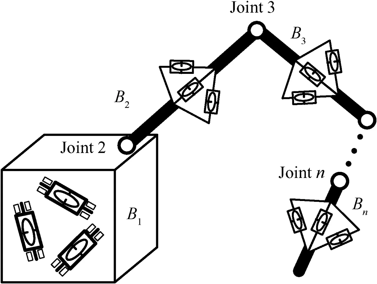
Fig.1 Space robot actuated by CMGs.
For the proposed system,we make the following assumptions.
Assumption 1.The position of the mass center of each CMG does not change as the CMG rotates about its gimbal axis,so the total first moment of Bi(including the CMGs on Bi,i=1,2,...,n)is constant in any body-fixed coordinate of Bi.
Assumption 2.The variation of the total moment of inertia for Bi(including the CMGs on Bi,i=1,2,...,n)due to the rotation of the CMGs on Biis small,so it can be ignored,i.e.,the total moment of inertia of Biis constant in any body-fixed coordinate of Bi.
From the view of robotic system level,the system can be regarded as a multibody system consisting of n moving bodies(the base and the links),and each cluster of CMGs can be considered as a part of the corresponding moving body.In the sequel,unless specified,Birefers to the moving body plus the ith cluster of CMGs.
3.Equations of motion
3.1.System coordinates and basic vectors
In this section,we propose to develop the equations of motion of the system using Kane's equations.To describe the motion of the system,several coordinate systems are introduced as follows(see Fig.2).
(1)Inertial coordinate systemThe origin o0is located at an arbitrary point in inertial space,and the axes of x0,y0and z0are fixed in the inertial space.
(2)The body-fixed coordinate system of the base,denoted as.The origin o1is located at an arbitrary point of B1,and the axes of x1,y1and z1are fixed in the base.

Fig.2 Coordinate systems and position vectors.
(3)The body-fixed coordinate system of the link Bi(i=2,3,...,n),denoted as Fi(oi–xiyizi).The origin oiis located at the center of the joint i,and the axes of xi,yiand ziare fixed in Bi.
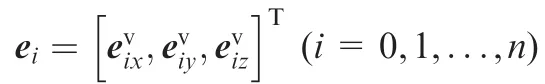
the component column matrix of Rvin F0.
3.2.System kinematics
Since the links are connected by ball joints,we use the modified Rodrigues parameters(MRPs),instead of the traditional joint angles,to describe the angular displacements of the bodies.Denotingas the MRPs of Fiwith respect to F0,we have32–34

where
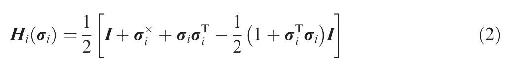
with the superscript''Xquot;the skew-symmetric cross product matrix of a 3X1 column matrix.
Choose the generalized speed matrix as

and the generalized displacement matrix as

then we obtain the kinematical equation of the system

where

3.3.System dynamics
Now we begin to derive the dynamical equations of the system.The velocity of a generic point in Bi(i=1,2,...,n)can be written in the form of Eq.(7).

where Gi∈R3X(3n+3)is the partial velocity matrix of the generic point in Bi,and given by the recursive expressions of Eq.(8).

where Ai,j∈R3X3represents the transform matrix from Fjto Fi.The angular velocity of Bi(i=1,2,...,n)can also be written in the similar form to Eq.(7),that is,

where Wi∈R3X(3n+3)is the partial angular velocity matrix of Bi,and given by
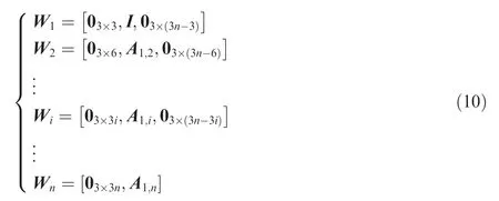
The acceleration vector of the generic point in Bican be obtained by taking time derivation of Eq.(7).

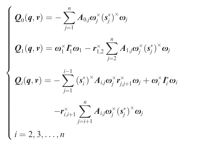
According to the Kane's equations in matrix form,35the generalized inertial force of the system can be evaluated by


is the positive definite mass matrix of the system,with m the total mass of the system;and

is the nonlinear inertial force matrix.The expressions of M(q)and Q(q,v)are given in Appendix A.
The active forces taken into consideration contain the following parts:(1)the control force acting on the base,denoted asis the component column matrix ofin F1);(2)the output torque of the ith cluster of CMGs acting on Bi(i=1,2,...,n),denoted asis the component column matrix ofin F1);(3)the disturbance torque acting on Bi(i=1,2,...,n),denoted asis the component column matrix ofin F1).Here we assume that the line ofpasses through the point o1,and then the active force matrix can be evaluated as
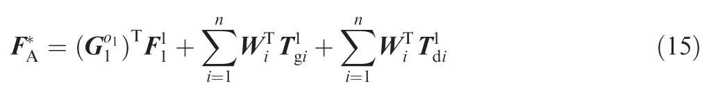

Substituting Eqs.(10)and(16)into Eq.(15)yields

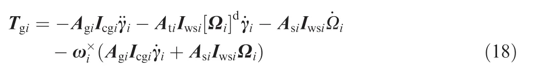
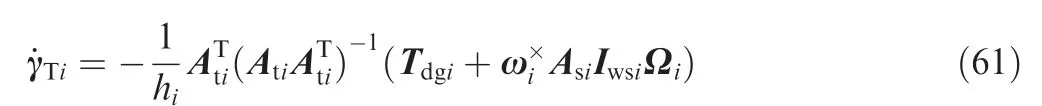
For a cluster of variable speed control moment gyroscopes(VSCMGs),Tgican be expressed as36∈Rniare column matrices whose elements are the gimbal angles and the rotor spin rates of the ith cluster of CMGs,respectively;Agi,Asiand Atiare 3Xnimatrices,whose columns are the component column matrices of the gimbal,rotor spin and transverse directional unit vectors in Fi,respectively;Icgi∈RniXniis a diagonal matrix,whose elements are the moments of inertia of the whole CMGs(gimbal plus rotor)about the gimbal axes;Iwsi∈RniXniis a diagonal matrix whose elements are the moments of inertia of the rotors about the rotor spin axes;is a diagonal matrix given by

In this study,we only consider using constant speed CMGs,and hence the termin Eq.(18)can be eliminated.Generally,the gimbal acceleration termis small enough to be ignored;37moreover,the angular momentum of the gimbal velocity termis small in comparison with the termso it can also be ignored.38Therefore,Tgican be simplified as

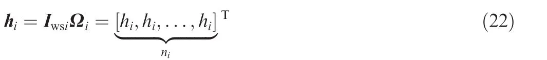
We reasonably assume that the rotors of the CMGs in the ith cluster have the same magnitude of angular momentum,denoted as hi.Given this,Eq.(20)can be written as

where
According to the Kane's equations in matrix form,35the dynamical equation of the system can be written in the form of Eq.(23).

Substituting Eqs.(12)and(17)into Eq.(23),we can arrange the dynamical equation as

where
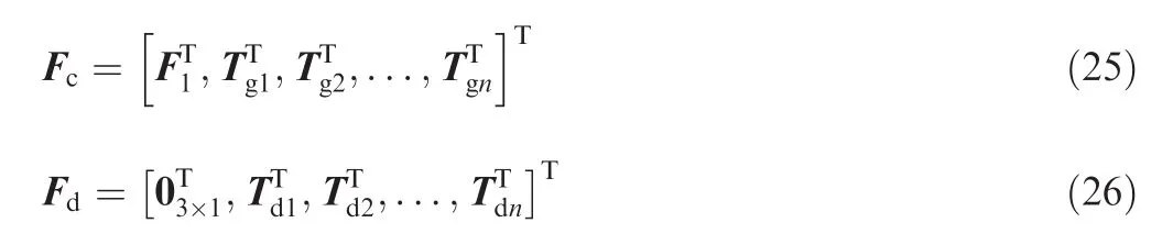
The dynamical Eq.(24)and the kinematical Eq.(5)together constitute the governing equations of motion of the system,and can be used for dynamical simulation,as well as the basis of system controller design.
4.Control problem statement
In general,the control objective of a space robot is to drive the manipulator variables to track their desired trajectories.Without loss of generality,here the manipulator variable is defined as

where Rnis the position of the end effector/payload(the tip body of the multibody system);Ψ is related to system displacement q by Jacobian matrix J(q)as

From the view of practical application,in this study,the base position R is not supposed to be controlled during the manipulator operation.To this end,the currentandare used for the desired variablesand,respectively,and the control force F1is set to be zero.Such method was also used by Senda and Nagaoka to address similar problems.39The control objective is to drive σi(i=1,2,...,n)to track its desired trajectory σid(t).We propose to design the control system using decentralized approach,in which the controller of σiis to be designed separately from those of σj(j≠ i).Therefore,it is necessary to separately investigate the governing rotational dynamical equation of Bi,which can be extracted from Eq.(24)and arranged in the form of
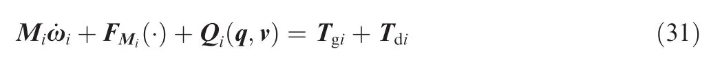
where Mi∈R3X3is the corresponding diagonal partition matrix of M(q),which is a constant matrix(see Appendix A);Qi(q,u)is the corresponding partition column matrix of Q(q,v);FMi(.)is given by

where Mij(q)(j=0,1,...,i-1,i+1,...,n)is the corresponding non-diagonal partition matrix of M(q).Explicitly,FMi(.)represents the direct disturbance torque of the other bodies acting on Bi.
From Eq.(1),we know that

Inserting Eq.(33)into Eq.(31)and left multiplying the resulting equation byyield


Considering the uncertainty of the inertial parameters,the mass matrixcan be divided into two parts,that is,where the first partis evaluated using the nominal inertial parameters,and the second partis the uncertain part.Given this,Eq.(34)can be rearranged in the form of Eq.(36).

where

and

Now we define

as the tracking error of σiand

as system state,and then Eq.(36)can be written in the state equation form of


is taken as system control input,and

is the''lumpedquot;uncertainty including the uncertainties of inertial parameters,system nonlinearity and unknown disturbances.To be strict,part of di(xi,t)can be precisely evaluated using the measurements of σiand ωi(for example,part of the system nonlinear term)despite the initial parameter uncertainty,and hence the part can be treated as known quantity in controller design.However,in order to simplify the controller algorithm,as well as to reduce the dependence of the controller design on system dynamical model,the whole term of di(xi,t)is still taken as uncertainty.
By now,the control problem becomes clear,that is,seeking for proper control input uifor system Eq.(41)to driveunder the disturbance of the''lumpedquot;uncertainty di(xi,t).
5.Control law design
To complete the description of system Eq.(41),we state the following assumptions.For convenience,in this section,the subscript''iquot;is omitted.
Assumption 3.The pair(A,B)is completely controllable.
Assumption 4.The uncertainty d(x,t)is continuous on its arguments.
Remark 1.Assumption 3 is distinctly valid for system Eq.(41).However,if the uncertainty d(x,t)contains joint friction torques,Assumption 4 may be called in question,because in some rough models the friction is discontinuous.But in accurate models which consider many aspects of friction such as stiction,stick–slip,Stribeck,etc.,friction is indeed continuous.40Therefore,Assumption 4 is also valid for system Eq.(41)in theory,although sometimes(especially when the friction direction is being changed)the friction behaves like discontinuous force and hence worsens system performance.
Since we propose to design the controller using SMC method,we begin with the first phase of a sliding surface construction so that the system restricted to the sliding surface produces desired behavior.41The resulting sliding surface is given by

where C∈R3X6is a constant matrix whose elements are chosen on the basis of the desired behavior.Here we assume that C is of full rank and the matrix CB is nonsingular.
After the sliding surface selection,the next phase is to design the control law so that the conditionis satisfied.This condition guarantees that the system trajectories reach the sliding surface and remain there for all subsequent time.The character of the''lumpedquot;uncertainty d(x,t),as the open literature has shown,has prominent effect on the control law design.If we can find a continuous positive scalar valued function ρ(x,t),such that ‖d(x,t)‖≤ ρ(x,t)for all(x,t)∈R6XR,then an SMC law guaranteeing ST˙Slt;0 can be developed using the results in Ref.41.However,for the system studied in this paper,such a function ρ(x,t)is not easy to be obtained,that is,the upper bound of the norm||d(x,t)||is uncertain.To handle this problem,Yoo and Chung22proposed the adaptation laws which are capable of estimating the upper bound of the norm||d(x,t)||,and designed a SMC law using the estimated upper bound.The control scheme in Ref.22is based on the assumption below.
Assumption 5.There are positive constants,c0and c1,such that‖d(x,t)‖ ≤ c0+c1‖x‖ = ρ(x,t)for all(x,t)∈ R6XR.
The control law proposed by Yoo and Chung22is given by

where KD∈R3X3is a positive definite matrix;ueqnomis the equivalent control for the nominal system of Eq.(41)by assuming that the uncertainty d(x,t)is zero,and determined by

The term uNis the nonlinear feedback control for suppression of the effect of the uncertainty,and defined as
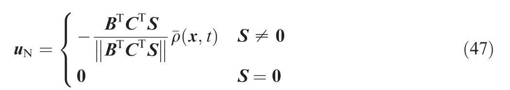


where q0and q1are adaptation gains with positive values.Yoo and Chung have proved that for system Eq.(41),if Assumptions 3–5 are valid,S=0 is asymptotically stable by employing the control law Eq.(45)with uNgiven in Eq.(47).By analyzing the structure of uN,Yoo and Chung also pointed out that the undesirable chattering phenomenon may occur due to the discontinuity of uNat S=0,and therefore they took a further step to modify uNas22
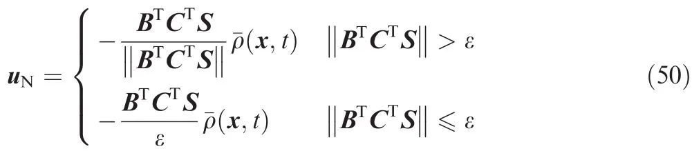
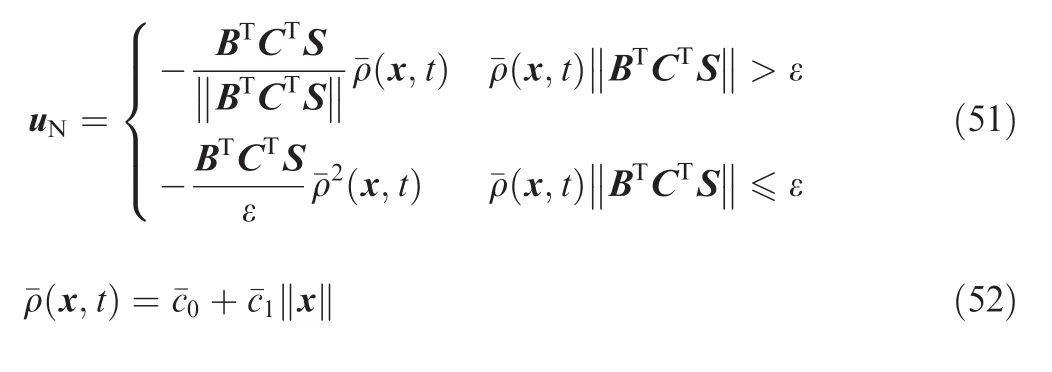
Later,Wheeler et al.24found that for the control law Eq.(45)with uNgiven in Eq.(50),the estimated gainsanddetermined by Eq.(49)may become unbounded in the boundary layer since the restriction to the sliding surface cannot always be achieved precisely.To eliminate the drawback,they modified uNand the adaptation laws as
where ψ0and ψ1are constants chosen by the designer.Wheeler et al.24have proved that if Assumptions 3–5 are valid,then the control law Eq.(45)with uNin Eq.(51)is continuous and in the closed loop system S(x)and all signals are uniformly ultimately bounded.However,direct application of Wheeler's control law to the system studied in this paper may arouse two problems.The first one is about the Assumption 5.Since the''lumpedquot;uncertainty d(x,t)contains complex nonlinearities,maybe the Assumption 5 is no more valid.The second one is about the control law itself.Though the system is proved to be uniformly ultimately bounded,there is no sufficient evidence showingandfor all(x,t),which implies there exists the possibility ofWhenthe control error may increase.The possibility ofincreases when||S||→0 becauseandmay be negative,and hencemay decrease at this point.Therefore,we hope to increasewhen||S||enters a neighborhood of zero to reduce the possibility ofand consequently reduce the control error.Motivated by the above two problems,we first expand Assumption 5 to Assumption 6 as shown below.
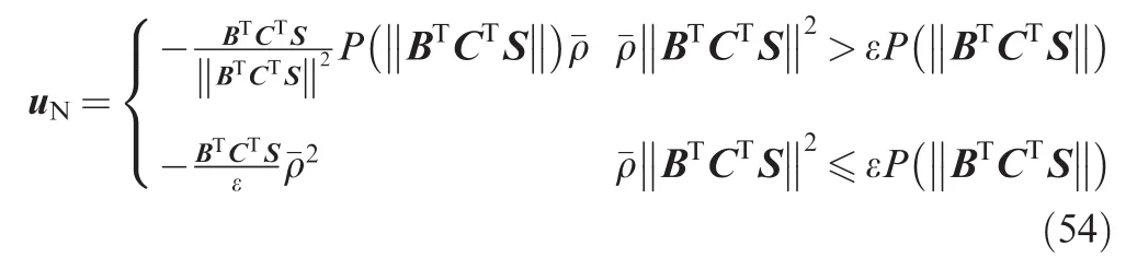
Assumption 6.There are positive constants,c0,c1,...,cN,where N is a given positive integer, such thatfor all(x,t)∈R6XR.
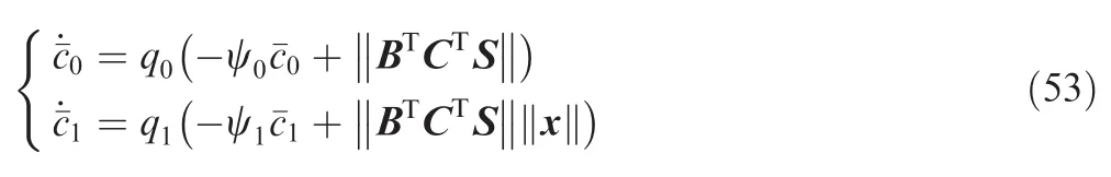
Based on Assumption 6,we then modify uNas
where P(.)is a scalar function.For any x≥0,the function P(x)in Eq.(54)is defined as

Therein,δgt;0 is a constant;g(x)is a scalar continuous function chosen by the designer which satisfies the following conditions.
Condition 1
(1)g(0)=0,g(δ)= δ.This condition guarantees the continuity of uN.
(2)g(x)gt;x,for x∈(0,δ).This condition ensures P(x)≥x for all x≥0,and hence the control error is reduced.

In Eq.(54),ˉρ(x,t)is given by


It can be proved that if Assumptions 3,4 and 6 are valid,the closed loop system constructed using control law Eq.(45)with uNin Eq.(54)is uniformly ultimately bounded.The proof is presented in Appendix B.
Remark 2.Since the nonlinear terms are all treated as system uncertainty,the positive integer N maybe cannot be chosen very precisely.To be conservative,N can be chosen as a larger integer,because if the integer matching the real system(denoted as Nr)is smaller than the selected integer N,Assumption 6 is still valid by letting ck=0(k=Nr+1,Nr+2,...,N).However,if Nrgt;N,the Assumption 6 is no more valid.
Remark 3.The purpose of the introduction of P(x)is to amplify the estimatedˉρ(x,t)in a predesigned interval of||BTCTS||∈ (0,δ)so as to reduce the control error.Generally,δ should be chosen as a small positive value,otherwise,the controller may take the risk of producing overlarge control input beyond the capacity of the actuators when||BTCTS||is far from zero.In Wheeler's control law and adaption law,the control error can also be reduced by increasing q0and q1and decreasing ψ0and ψ1,but with the same risk as mentioned above.In a word,we expect control error reduction at the cost of few increase of control input.
6.Steering law for CMGs
Once the control input uiis obtained by the control law,the desired value of the CMG torque Tgi,denoted as Tdgi,can be uniquely determined using Eqs.(37)and(42)as given below.

Based on Eq.(20),we know that to provide the desired torque Tdgi,the gimbal angular velocity of the ith cluster of CMGs,must satisfy

Here we assume ni≥4(i=1,2,...,n).Because of the redundancy of the CMGs,there are infinite solutions ofsatisfying Eq.(59).To avoid the configuration singularity,we use the well-developed steering law with null motion,that is,

where

is used to provide the desired control torque,and is the null motion used to avoid the con figuration singularity.Therein,αiis a positive scalar parameter chosen by the designer,andis the measurement of con figuration singularity.
7.Numerical example
7.1.System configuration and parameters
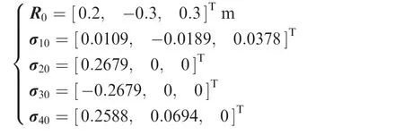
The numerical example is concerned with a system containing a cubic base and three links.The length of side of the base is 1.5 m,the length of the link B2and B3is 1.5 m,and that of the link B4(the end effector/payload)is 0.6 m.The origin of F1is located at the geometrical center of the base,and the axes of F1are parallel to the edge lines of the cube.When the axes of F1are parallel to the corresponding axes of the bodyfixed coordinates of the links,the system con figuration is shown in Fig.3(a).Different CMG configurations can be adopted to provide the control torques provided that ni≥4(i=1,2,...,n);nevertheless,we select the pyramid configuration due to its close-to-spherical angular momentum envelop,i.e.,a cluster of CMGs arranged in pyramid configuration is installed on the base as well as each link.The centering axis of the pyramid is along the direction of the ziaxis of Fi,and the gimbal axis of each CMG has the same included angle of β =53.1°with the centering axis(see Fig.3(b),whereand)represent the gimbal angular velocity and rotor angular momentum of the jth CMG in ith cluster,respectively).Table 1 lists system inertial parameters.The moments of inertia and the first moments are evaluated based on the corresponding body-fixed coordinates.As the values of the first moments are unused in controller design,we merely need to present the true values.
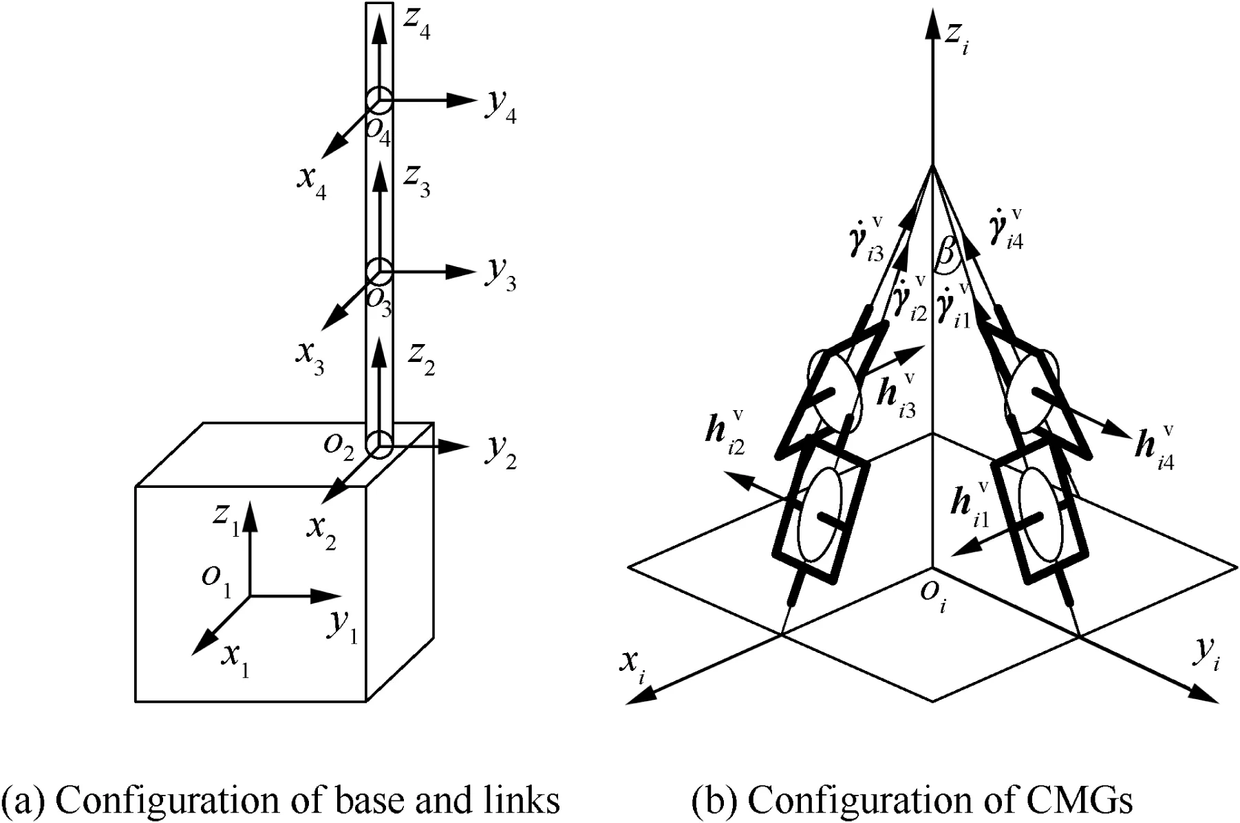
Fig.3 Configuration of system in numerical example.
The geometric parameters are

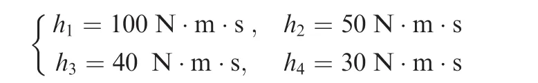
The magnitudes of the angular momentums of the CMGs,hi(i=1,2,3,4),are chosen as
The initial gimbal angles of the CMGs are chosen to be

7.2.Control objective


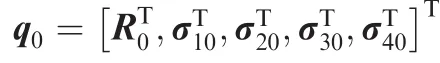
where r4t=[0,0,0.6]Tm is the endpoint position of the link B4in F4.Because R is not controlled,we then use the current R,˙R and¨R as the desired values ofandrespectively.The initial values of σ1d(t),R4d(t)and σ4d(t)are determined by the initial values of the desired system displacements inwhich are set to be
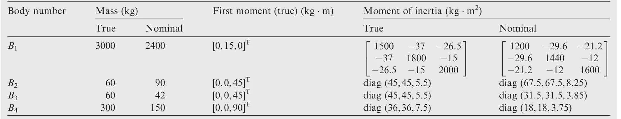
Table 1 System inertial parameters.
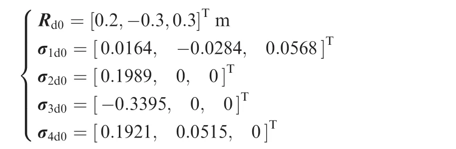
By Eq.(63),the corresponding initial values of σ1d(t),R4d(t)and σ4d(t)are then computed as

σ1d(t)and σ4d(t)are determined by quintic polynomials with the desired initial values of σ1d0and σ4d0and the desired final values ofandand given as
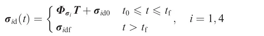


It is easy to verify that σid(t)(i=1,4)satisfies the following constraints:

Because σ1dfand σ4dfare constant values of zero,the attitudes of both the base and the end effector/payload are supposed to maintain stable control along desired approaching trajectories.
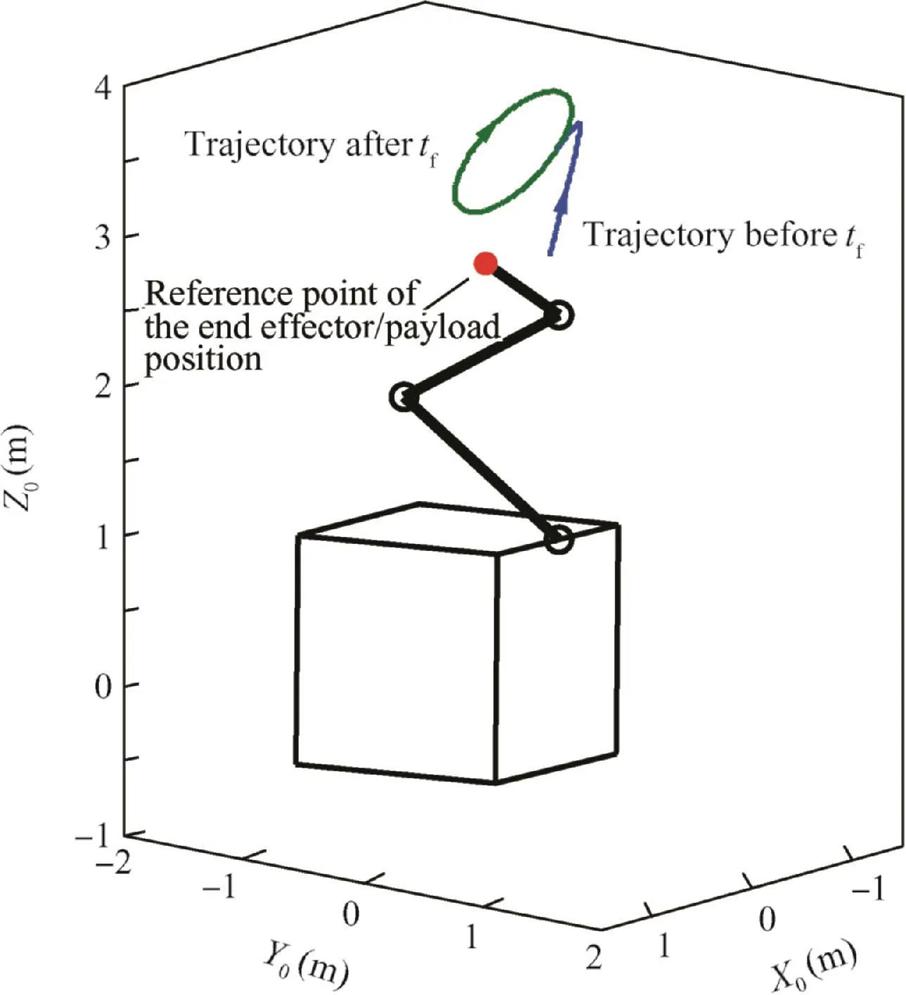
Fig.4 System initial configuration and desired position trajectory of end effector/payload.
where
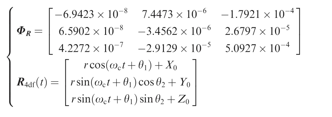
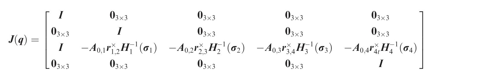
The Jacobian matrix J(q)which associates the manipulator variable Ψ with system displacement q is
[-0.4330,-0.1250,3.3835]Tm.When tgt;tf,R4d(t)is a predesigned continuous trajectory instead of a constant.The expression of R4d(t)is given as

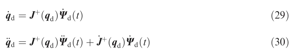
Based on Ψd(t)given above,the desired displacement qd,as well as its first and second time derivativesand,can be obtained using the trajectory planning algorithm presented in Section 4 and the Jacobian matrix J(q)given above,and then the control objective is to drive σi(i=1,2,3,4)to track the desired trajectory σidin qd.
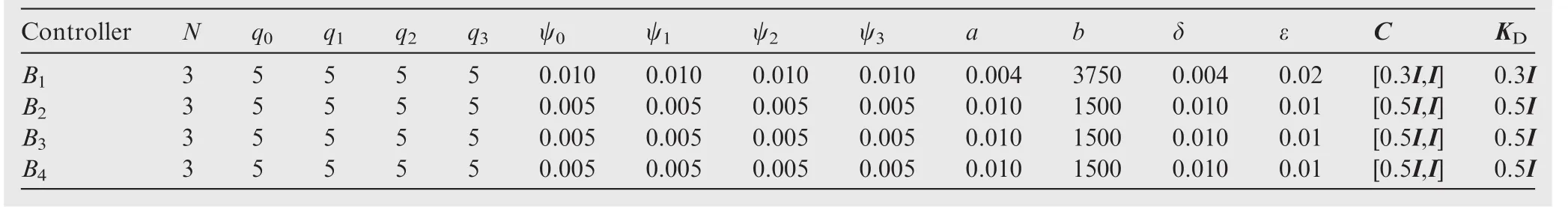
Table 2 System control parameters.
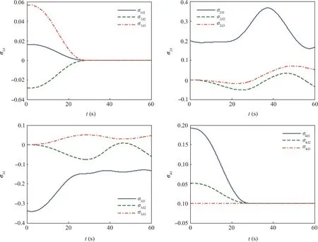
Fig.5 Desired trajectories of σi(i=1,2,3,4).
7.3.Disturbance torques
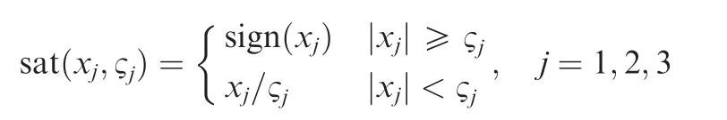
The disturbance torques taken into consideration mainly include two parts:the joint friction torques and other possible disturbance torques.Precise modeling of the friction torque of a ball joint is quite complex,and in the simulation,the following model is used to roughly simulate the friction torque of jointiacting on Bi(i=2,3,4).

where, for any x=[x1,x2,x3]T∈R3and ?=sat(x,?)=[sat(x1,?1),sat(x2,?2),sat(x3,?3)]T,and therein,sat(xj,?j)(j=1,2,3)is a saturation function defined as
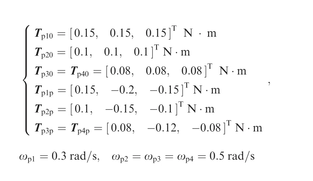
Other possible disturbance torques acting on Bi(i=1,2,3,4)are considered to be the sum of a constant torque and a periodic torque with the argument of time t,and given as

Note that when the friction torque of jointiacts on Bi,its reaction torque will also act on Bi-1,and then the disturbance torques in Fd(see Eq.(26))in the simulation are given as

The related constant parameters are chosen to be


Fig.6 Control errors of σi(i=1,2,3,4).
7.4.Control parameters

Fig.7 Position errors of the end effector/payload.
For the controller of Bi(i=1,2,3,4),the function P(x)in Eq.(55)is denoted as Pi(x)and designed as
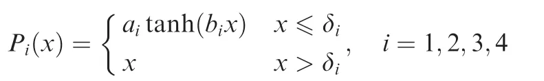
where the parameters of ai,biand δiwhich guarantee Condition 1,as well as other control parameters,are listed together in Table 2.
For each cluster of CMGs,the null motion coefficient is chosen to be the same value of αi=0.5(i=1,2,3,4).
7.5.Simulation results and analysis
Fig.5 shows the desired trajectories of σi(i=1,2,3,4),,solved using the trajectory planning algorithm presented in Section 4 based on the given desired manipulator variable Ψd(t).Fig.6 shows the control errors of σi(i=1,2,3,4)defined as Δσi=||σi- σid||,and Fig.7 shows the position errors of the end effector/payload defined as ΔR4=||R4-R4d(t)||under the direct control of σi.For comparison,the results using the control law Eq.(45)with uNgiven in Eq.(54)(the proposed control law in this paper)and those using the control law Eq.(45)with uNgiven in Eq.(51)are both presented in Figs.6 and 7.The two control laws use the same control parameters(if they have)as given in Section 7.4 to obtain comparable results.As can be seen,the control errors of the control law with uNgiven in Eq.(54)are conspicuously smaller than those of the control law with uNgiven in Eq.(51),which verifies the effectiveness of the proposed improvements in the control law and adaptation laws.

Fig.8 Magnitudes of Tgi(i=1,2,3,4).
Fig.8 gives the magnitudes of Tgi,i.e.,Tgi=||Tgi||(i=1,2,3,4).By comparing Tgiproduced by uNgiven in Eq.(54)with those produced by uNgiven in Eq.(51),we can see that,as expected,the control law with uNgiven in Eq.(54)does not produce noticeably larger control torque than that with uNgiven in Eq.(51)although it does achieve better control accuracy.Moreover,no chattering phenomenon occurs in the simulations of both two controllers due to their continuity in control inputs.Further simulation results show that if the amplification range in the adaptation laws is extended,better control accuracy may be achieved but at the possible cost of increasing the magnitude of the control torques.
The steering law with null motion for the CMGs works well during the simulation.Fig.9 shows the configuration singularity measurements of the CMGs(the results in Fig.9 are achieved by the control law with uNgiven in Eq.(54)),including those with null motion and without null motion.Though the CMG clusters do not run into singularity even when the null motion is not added,in most of the time,the measurements with null motion are much larger than those without null motion,which indicates effective singularity avoidance of the null motion.
Fig.10 shows system configurations at different moments during the control.The coordinate with solid line axes represents F4,and that with dotted line axes represents the desired orientation of F4.The same color represents the same axis.The origin of F4is located at the position reference point of the end effector/payload,and that of the desired coordinate is located at the desired position of the end effector/payload.At the initial moment,both the position and the orientation of the end effector/payload have conspicuous deviations from the desired ones,and the base attitude also has visible deviation from the desired attitude of[0,0,0]T.Under the control of the proposed control law,the deviations decrease gradually and enter into a small boundary ultimately.
8.Conclusions
(1)Decentralized controller design for trajectory tracking of the space robot system faces the challenge of large system uncertainty with unknown upper bound.The sliding mode controller with the improved adaptation laws proposed in this paper can achieve uniformly ultimate boundedness of the closed loop system.The amplification function introduced in the adaptation laws effectively reduces the control error with out notably increasing the control input magnitude provided that the amplification range is properly selected,and the control law is free from the chattering problem due to its continuity.The proposed controller is expected to be applicable to systems with different configurations because the controller for each link is designed separately as a sole system.

Fig.9 Singularity measurements of CMGs.
(2)It should also be noticed that as angular momentum devices,the CMGs always face the risk of angular momentum saturation.Therefore,the CMG-actuating design cannot be applied to terrestrial robotic systems due to continuous gravitational torques.Even in space environment,reducing the possibility of saturation is still of great significance;therefore the approach to realize this objective is regarded as important future work.The approach may be implemented along two different routes.From the angle of hardware,we can increase the CMG angular momentum by increasing either the moment of inertia or the spin rate of the CMG rotor to reduce the possibility of saturation;however,such methods will definitely increase the mass of the CMGs,which,to some extent,equates to increasing the payload mass of the robotic manipulator.Therefore,we need an appropriate optimization method to balance the angular moment of the CMGs and the load capacity of the robotic manipulator.From the angle of algorithm,we may utilize the redundancy of DOC of the joints to redistribute the three-axis angular momentum of each link so as to avoid saturation.In other words,with the redundancy of DOC of the joints,we may seek a trajectory helping saturation avoidance in joint space from infinite trajectories which satisfy the end effector/payload trajectory constraints.
Acknowledgement
This study was supported by the National Natural Science Foundation of China(No.11272027).
Appendix A
Appendix B
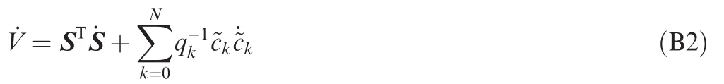
Define a Lyapunov function as

where

Differentiating V with respect to time yields

where m is the total mass of the system,and

Therein,mjis the mass ofdm is the first moment of Biin Fi,anddm is the moment of inertia of Biin Fi.

where
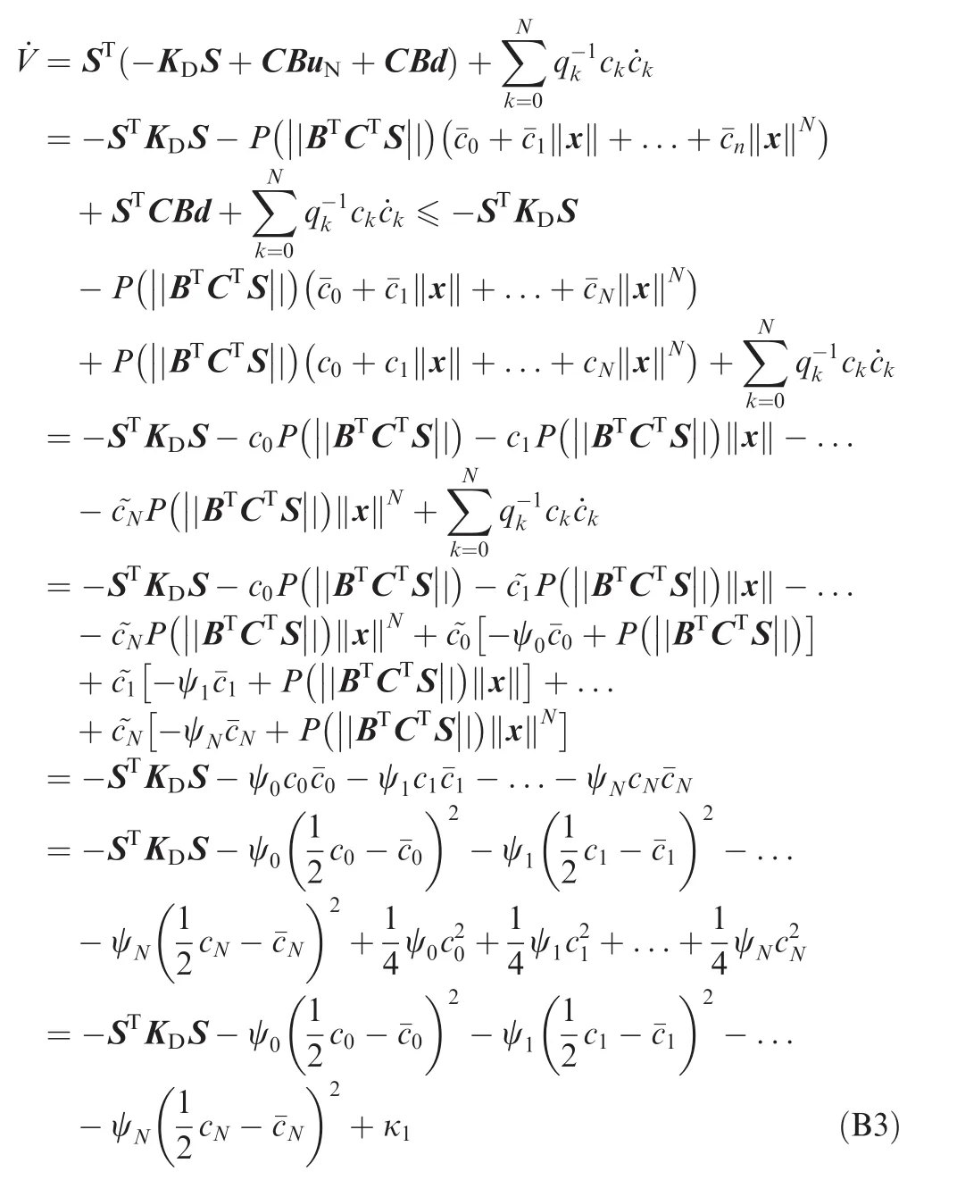
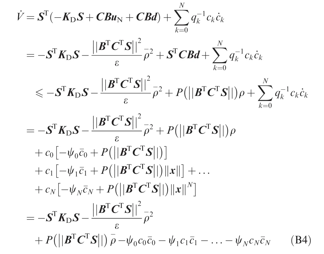
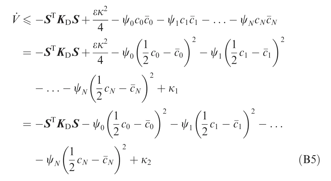
With Eqs.(B3)and(B5),we may conclude that the closed loop system is of uniformly ultimate boundedness using the results in Ref.42.is a constant.
1.Ehrenwald L,Guelman M.Integrated adaptive control of space manipulators.J Guid Control Dyn 1998;21(1):156–63.
2.Guo YS,Chen L.Adaptive neural network control for coordinated motion of a dual-arm space robot system with uncertain parameters.Appl Math Mech 2008;29(9):1131–40.
3.Jia YH,Hu Q,Xu SJ.Dynamics and adaptive control of a dualarm space robot with closed-loop constraints and uncertain inertial parameters.Acta Mech Sinica 2014;30(1):112–24.
4.Flores-Abad A,Wei Z,Ma O,Pham K.Optimal control of space robots for capturing a tumbling object with uncertainties.J Guid Control Dyn 2014;37(6):2014–7.
5.Green A,Sasiadek JZ.Intelligent tracking control of a free- flying flexible space robot manipulator.AIAA guidance,navigation and control conference and exhibit;2007 Aug 20–23;Hilton Head,South Carolina.Reston:AIAA;2007.p.132–56.
6.Meirovitch L,Chen Y.Trajectory and control optimization for flexible space robots.J Guid Control Dyn 1995;18(3):493–502.
7.Billing-Ross JA,Wilson JF.Pointing system design for lowdisturbance performance.AIAA guidance,navigation,and control conference;1988 Aug 15–17;Minneapolis(MN).Reston:AIAA;1988.p.444–51.
8.Osuka K,Yoshida K,Ono T.New design concept of space manipulator-a proposal of torque-unit manipulator.Proceedings of the 33rd conference on decision and control;1994 Dec 14–16;Lake Buena Vista(FL).Piscataway(NJ):IEEE Press;1994.p.1058 1823–5.
9.Peck MA,Paluszek MA,Thomas SJ,Mueller JB.Controlmoment gyroscopes for joint actuation:A new paradigm in space robotics.Proceedings of the 1st space exploration conference:continuing the voyage of discovery;2005 Jan 30–Feb 1;Orlando(FL).Reston:AIAA;2005.p.204–33.
10.Peck MA.Low-power,high-agility space robotics.AIAA guidance,navigation and control conference and exhibit;2005 Aug 15–18;San Francisco(CA).Reston:AIAA;2005.p.3759–70.
11.Carpenter MD,Peck MA.Dynamics of a high-agility,low-power coelostat telescope.AIAA guidance,navigation and control conference and exhibit;2006 Aug 21–24;Keystone(CO).Reston:AIAA;2006.p.4175–91.
12.Carpenter MD,Peck MA.Minimum-power robotic maneuvering using control-moment gyroscopes.AIAA guidance,navigation and control conference and exhibit;2007 Aug 20–23;Hilton Head(SC).Reston:AIAA;2007.p.210–22.
13.Carpenter MD.Power-optimal steering of a space robotic system driven by control-moment gyroscopes.AIAA guidance,navigation and control conference and exhibit;2008 Aug 18–21;Honolulu(HI).Reston:AIAA;2008.
14.Brown D,Peck MA.Scissored-pair control-moment gyros:a mechanical constraint saves power.J Guid Control Dyn 2008;31(6):1823–6.
15.Brown D.Control moment gyros as space-robotics actuators.AIAA guidance,navigation and control conference and exhibit;2008 Aug 18–21;Honolulu(HI).Reston:AIAA;2008.
16.Brown D,Peck MA.Energetics of control moment gyroscopes as joint actuators.J Guid Control Dyn 2009;32(6):1871–83.
17.Jia YH,Zhao N,Xu SJ.Trajectory tracking control of space robot actuated by control moment gyroscopes.J Beijing Univ Aeronaut Astronaut 2014;40(3):285–91 Chinese.
18.Zhao N,Jia YH,Xu SJ.Trajectory tracking control of a reactionless space robot.Chin Space Sci Technol2014;34(2):13–21 Chinese.
19.Feng Y,Yu XH,Man ZH.Non-singular terminal sliding mode control of rigid manipulators.Automatica 2002;38(12):2159–67.
20.Ferrara A,Magnani L.Motion control of rigid robot manipulators via first and second order sliding modes.J Intell Robot Syst Theory Appl 2007;48(1):23–36.
21.Ferrara A,Incremona GP.Robust motion control of a robot manipulator via integral suboptimal second order sliding modes.Proceedings of the 52nd IEEE conference on decision and control;2013 Dec 10–13;Florence,Italy.Piscataway(NJ):IEEE Press;2013.p.1107–12.
22.Yoo DS,Chung MJ.A variable structure control with simple adaptation laws for upper bounds on the norm of the uncertainties.IEEE Trans Autom Control 1992;37(6):159–65.
23.Leung TP,Zhou QJ,Su CY.An adaptive variable structure model following control design for robot manipulators.IEEE Trans Autom Control 1991;36(3):347–52.
24.Wheeler G,Su CY,Stepanenko Y.A sliding mode controller with improved adaptation laws for the upper bounds on the norm of uncertainties.Automatica 1998;34(12):1657–61.
25.Tao CW,Chan ML,Lee TT.Adaptive fuzzy sliding mode controller for linear systems with mismatched time-varying uncertainties.IEEE Trans Syst Man Cybern B Cybern 2003;33(2):283–94.
26.Mu?oz D,Sbarbaro D.An adaptive sliding-mode controller for discrete nonlinear systems.IEEE Trans Ind Electron.2000;47(3):574–81.
27.Plestan F,Shtessel Y,Brégeault V,Poznyak A.New methodologies for adaptive sliding mode control.Int J Control 2010;83(9):1907–19.
28.Cong BL,Liu XD,Chen Z.Improved adaptive sliding mode control for a class of second-order mechanical systems.Asian J Control 2013;15(6):1862–6.
29.Li P,Zheng ZQ.Robust adaptive second-order sliding-mode control with fast transient performance.IET Control Theory Appl 2012;6(2):305–12.
30.Wang L,Sheng YZ,Liu XD.A novel adaptive high-order sliding mode control based on integral sliding mode.Int J Control 2014;12(3):459–72.
31.Hughes PC.Spacecraft attitude dynamics.New York:John Wileyamp;Sons Inc.;1986.p.7–8.
32.Schaub H,Junkins JL.Stereographic orientation parameters for attitude dynamics:a generalization of the Rodrigues parameters.J Astronaut Sci 1996;44(1):1–19.
33.Jin YQ,Liu XD,Qiu W,Hou CZ.Time-varying sliding mode controls in rigid spacecraft attitude tracking.Chin J Aeronaut 2008;21(4):352–60.
34.Cong BL,Liu XD,Chen Z.Exponential time-varying sliding mode control for large angle attitude eigenaxis maneuver of rigid spacecraft.Chin J Aeronaut 2010;23(4):447–53.
35.Banerjee AK,Kane TR.Large motion dynamics of a spacecraft with a closed loop,articulated,flexible appendage.Proceedings of the 25th AIAA structures,structural dynamics and materials conference;1984 May 14–16;Palm Springs(CA).Reston:AIAA;1984.
36.Yoon H,Tsiotras P.Spacecraft adaptive attitude and power tracking with variable speed control moment gyroscopes.J Guid Control Dyn 2002;25(6):1081–90.
37.Schaub H,Vadali SR,Junkins JL.Feedback control law for variable speed control moment gyroscopes.J Astronaut Sci 1998;46(3):307–28.
38.Yoon H,Tsiotras P.Adaptive spacecraft attitude tracking control with actuator uncertainties.AIAA guidance,navigation and control conference and exhibit;2005 Aug 15–18;San Francisco(CA).Reston:AIAA;2005.p.5311–22.
39.Senda K,Nagaoka H.Adaptive control of free-flying space robot with position/attitude control system.J Guid Control Dyn 1999;22(3):488–90.
40.De Wit CC,Olsson H,.Astr?m KJ,Lischinsky P.A new model for control of systems with friction.IEEE Trans Autom Control 1995;40(3):419–25.
41.Walcott BL,Zak SH.Combined observer-controller synthesis for uncertain dynamical systems with applications.IEEE Trans Syst Man Cybern 1988;18(1):367–71.
42.Corless MJ,Leitmann G.Continuous state feedback guaranteeing uniform ultimate boundedness for uncertain dynamic systems.IEEE Trans Autom Control 1981;26(5):1139–44.
Jia Yinghongis an associate professor at School of Astronautics,Beihang University,Beijing,China.He received the Ph.D.degree from Harbin Institute of Technology in 2005.His current research interests are dynamics and control of space robot/multibody system,spacecraft attitude dynamics and control,and sliding mode control.
Xu Shijieis a professor and Ph.D.supervisor at School of Astronautics,Beihang University,Beijing,China.His current research interests are nonlinear orbital dynamics and control in deep space exploration,spacecraft dynamics and control,and robust control theory and application.
11 February 2015;revised 26 May 2015;accepted 22 February 2016
Available online 10 May 2016
Adaptation law;
Ball joint;
Control moment gyroscopes;
Sliding mode control;
Space robot;
Trajectory tracking
?2016 Chinese Society of Aeronautics and Astronautics.Production and hosting by Elsevier Ltd.This is an open access article under the CCBY-NC-ND license(http://creativecommons.org/licenses/by-nc-nd/4.0/).
*Corresponding author.Tel.:+86 10 82339750.
E-mail address:jia_yingh@163.com(Y.Jia).
Peer review under responsibility of Editorial Committee of CJA.
 CHINESE JOURNAL OF AERONAUTICS2016年3期
- CHINESE JOURNAL OF AERONAUTICS的其它文章
- Optimization on cooperative feed strategy for radial–axial ring rolling process of Inco718 alloy by RSM and FEM
- Prediction of cutting forces in ball-end milling of 2.5D C/C composites
- Performance optimization of grooved slippers for aero hydraulic pumps
- Modeling of reliability and performance assessment of a dissimilar redundancy actuation system with failure monitoring
- Motion synchronization in a dual redundant HA/EHA system by using a hybrid integrated intelligent control design
- Remaining useful life prediction based on the Wiener process for an aviation axial piston pump