Numerical Study of Air Nozzles on Mild Combustion for Application to Forward Flow Furnace
(State-Key Laboratory of Chemical Engineering, School of Mechanical and Power Engineering, East China University of Science and Technology, Shanghai 200237)
Numerical Study of Air Nozzles on Mild Combustion for Application to Forward Flow Furnace
Liu Bo; Wang Yuanhua; Xu Hong
(State-Key Laboratory of Chemical Engineering, School of Mechanical and Power Engineering, East China University of Science and Technology, Shanghai 200237)
An attempt was made to extend mild combustion to forward fl ow furnace, such as the re fi nery and petrochemical tube furnace. Three dimensional numerical simulation was carried out to study the performance of this furnace. The Eddy Dissipation Concept (EDC) model coupled with the reaction mechanism DRM-19 was used. The prediction showed a good agreement with the measurement. The effect of air nozzle circle (D), air nozzle diameter (d), air nozzle number (N), and air preheating temperature (Tair) on the fl ow, temperature and species fi elds, and the CO and NO emissions was investigated. The results indicate that there are four zones in the furnace, viz.: a central jet zone, an ignition zone, a combustion reaction zone, and a fl ue gas zone, according to the distribution pro fi les of H2CO and OH. The central jet entrains more fl ue gas in the furnace upstream with an increasingDwhile the effect ofDis negligible in the downstream. The air jet momentum increases with a decreasingdor an increasingTair, and entrains more fl ue gas. The effect ofNis mainly identi fi ed near the burner exit. More heat is absorbed in the radiant section and less heat is discharged to the atmosphere with a decreasingdand an increasingNas evidenced by the fl ue gas temperature. The CO and NO emissions are less than 50 μL/L and 10 μL/L, respectively, in most of conditions.
mild combustion; re fi nery and petrochemical tube furnace; forward fl ow con fi guration; low pollutant emissions; CFD.
1 Introduction
In refinery and petrochemical plant, furnace is one of the most important equipment for heating the feedstocks or products. Nitrogen oxides, NOx, are produced from combustion process inside the tubular furnace. Low-NOxburner (LNB) has been widely used to meet more stringent government guidelines to minimize pollutant impact on the environment. LNB can reduce NOxemissions by 30%–50%[1-2]but sometimes may cause greater CO formation[1,3]. In the early 1990s, mild (moderate or intense low-oxygen dilution) combustion became a research topic in the field of NOxabatement[4]. Mild combustion, also known as high temperature air combustion (HiTAC)[5], fl ameless combustion or fl ameless oxidation (FLOX)[4], or colorless distributed combustion (CDC)[6], is one of the most promising technologies, which combines high thermal efficiency and low pollutants emission. In the mild mode, fuel is slowly oxidized in a distributed reaction zone where oxygen is highly diluted by recirculated fl ue gas and the temperature can exceed the local auto-ignition point. Therefore, the fl ame is invisible, and the peak fl ame temperature is significantly reduced, while the temperature distribution is rather uniform, and the NOxemission is dramatically reduced[7-8]. This technology has been successfully applied to many industrial furnaces, for example metal and steel reheating and heat treatment furnaces, and has a great potential to bene fi t other applications.
The mild combustion has been realized under different operating conditions. Intense recirculation of hot fl ue gas inside the furnace is the key factor determining the mild regime[6,8]. The flow field is controlled by the nozzles arrangement, the furnace shape, the mixing pattern, and the momentum of reactants. Arghode and Gupta[9]investigated a reverse fl ow mode of CDC for application to gasturbine combustor. The air injection port was positioned at the combustor exit end and the fuel injection port could be changed to give different con fi gurations. Their results indicated that the reverse-cross-flow configuration produced lowest CO and NO emissions. In another work[10], they investigated a forward fl ow mode of CDC, in which the air injection port was positioned at the opposite side of the combustor exit. Ultra-low NOxemission was achieved but the CO emission was high due to the shorter residence time. Tu, et al.[11]numerically investigated the effect of combustion chamber shape on the mild combustion of natural gas in a forward flow furnace. A larger angle between the furnace roof and the sidewall achieved stronger recirculation flow field with more flue gas entrained into reactants, resulting in broader reaction zone, lower peak fl ame temperature, and lower NOxemission. Huang, et al.[12-13]performed mild combustion of syngas in a parallel jet forward flow combustor. The effects of air/fuel momentum fl ux ratio and air preheating temperature were examined for ultra-low CO and NOxemissions. Their equivalence ratio varied from 0.25 to 0.6 according to the operating parameters of gas turbine combustor. In another paper of Huang, et al.[14], they investigated the effect of fuel injection velocity on mild combustion in an axially-staged combustor. Gu, et al.[15]carried out numerical simulation of slab heating process in a regenerative walking beam reheating furnace under HiTAC mode. Their results showed that the temperature distribution in the furnace was quite uniform.
As reviewed above, the mild combustion has been researched for application to gas turbine combustor and metal reheating furnace. Very few studies have focused on the tube furnace for application of mild combustion. In this furnace, reactants are injected from one side (e.g. the bottom side) and exit is located at the opposite side (e.g. the top side)[16]; therefore, the furnace is a forward flow configuration. Li, et al.[17]analyzed the application prospects of regenerative combustion technology in tube furnace. The tube furnace which will be equipped with several pairs of HiTAC burners needs to be redesigned. The burners have ceramic honeycomb heat exchangers incorporated. The fl ue gas is sucked by a fan via the air nozzles over these honeycombs (thus heating them) for regeneration of the heat. Several burners are fi ring simultaneously, while the other several burners are subject to recuperation. After a time interval (e.g. 30 s) they switch over alternately, and the fi ring burners start heat recuperation, and vice versa. In order to extend the mild combustion technology to the existing furnace, it is necessary to research the realization of mild combustion in a forward fl ow furnace. Ayoub, et al.[18]carried out an experimental study of mild combustion in a laboratory-scale pilot furnace provided with the forward fl ow con fi guration. They performed the fl ue gas composition measurement and the reaction zone topology by OH chemiluminescence imaging. Rebola, et al.[19]investigated experimentally the mild oxidation phenomena of methane in a small scale furnace with forward flow configuration. The flue gas data showed that the NOxemission was always low but the CO emission was strongly affected by the excess air factor and the preheating temperature of the combustion air. Rebola, et al.[20]also performed numerical simulation of the mild combustion furnace with different turbulence and combustion models and different reaction mechanisms. Their results showed that the eddy dissipation concept (EDC) model along with the detailed mechanism yielded rather good predictions validated by measurements.
In this study, the mild combustion was applied to a laboratory-scale forward fl ow furnace. The air nozzles arrangement was numerically studied for achieving a better performance. Firstly, the prediction was validated with the experimental data of Rebola, et al[19-20]. Secondly, the effects of the air nozzle circle (D), the air nozzle diameter (d), the air nozzle number (N), and the air preheating temperature (Tair) on the fl ow and combustion characteristics, and the fl ue gas emissions were investigated.
2 Physical and Numerical Modeling
2.1 System description and problem de fi nition
The furnace adopted in this study is the one used by Rebola, et al[19-20]. Figure 1 shows the furnace con fi guration and its dimension. The employed boundary conditions are summarized in Table 1. The 15 arrangements of the gas and air nozzles are summarized in Figure 2. Runs 1 to 5 allow quantifying the effect of air nozzle circle diameterD(12—30 mm) on the furnace performance; Runs 6 to 10 allow quantifying the effect of air nozzle diam-eterd(5—9 mm); and, fi nally, Runs 11 to 15 allow quantifying the effect of air nozzle numberN(4—12) while maintaining constant the air nozzles area. The air preheating temperature (Tair) ranging from 373 K to 773 K is studied in Run 10 and is maintained at 773 K for other runs.
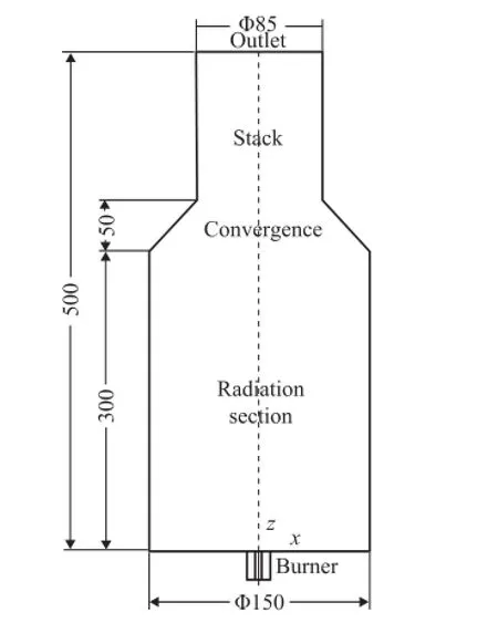
Figure 1 Con fi guration of the mild furnace (dimensions in mm)
2.2 Mathematical models
The governing equations for continuity, momentum, energy, species, ideal gas and chemical kinetic reactions are solved in the combustion simulation process. In the work of Rebola, et al.[20]turbulence was modeled usingfour different RANS-based models, namely the standard, the RNG and the realizablek-εmodels, and the Reynolds stress model (RSM). The calculations showed that the different turbulence models employed did not yield signi fi cant differences in overall results, while the standardk-εmodel could provide the best results. Therefore, the standardk-εmodel was adopted in this study. The RSM, the realizable and the RNGk-εmodels were expected to perform either better than or to be similar to the standardk-εmodel. However, the flow did not exhibit flow features in which the standardk-εwas known to perform poorly, such as adverse pressure gradient, strong streamline curvature or swirl, and this might be the reason for only marginal differences among the predictions of these turbulence models.
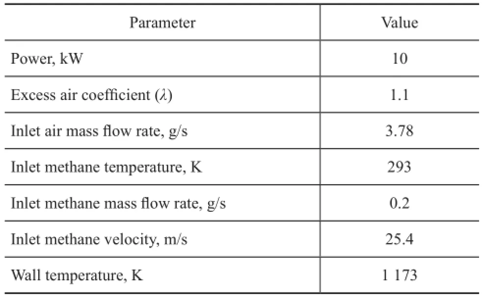
Table 1 Simulation conditions
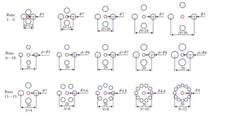
Figure 2 Arrangements of the fuel and air nozzles
The eddy dissipation concept (EDC) model coupledwith the detailed chemistry mechanism leads to good numerical predictions[20-21]. The EDC model assumes that reaction occurs in small turbulent structures, where dissipation of turbulent kinetic energy takes place, called the fi ne scales. Rebola, et al.[20]considered three kinetic mechanisms to describe methane oxidation, namely the Kee-58, the DRM-19, and the GRI-2.11. The DRM-19 mechanism[22]is a subset of the GRI-1.2 full mechanism, which consists of 19 species and 84 reactions. There were no significant differences among the computational results. Thus, the DRM-19 mechanism was adopted in this study for saving the computational time. To implement the detailed chemistry and reduce computational cost of time integration, the in situ adaptive tabulation (ISAT) algorithm of Pope[23]was used. Finally, the ISAT error tolerance was set at 10-5to ensure that the results were not changed further.
The radiant heat transfer was simulated with the discrete ordinates (DO) model. Absorption coef fi cient of gaseous medium used in the radiation equation was modeled with the weight sum of grey gas (WSGG) model, which was a reasonable compromise between the over-simpli fi ed grey gas model and the complete model[24].
The NOxformation was evaluated by the post-processing approach, because the low NOxconcentration had a reduced impact on other fl ow properties[25]. In order to better understand the mechanisms responsible for the NOxemission in the mild combustion furnace, the thermal-NO, prompt-NO, N2O-intermediate, and NO-reburning mechanisms were considered in this study. The O radical concentration in the thermal-NO and N2O-intermediate routes, as well as the OH radical concentration in the thermal-NO, were predicted in the EDC model. The prompt NO formation was modeled using a global kinetic parameter derived by De Soete[26]. The N2O-intermediate mechanism was solved via a transport equation. In order to take into account the effect of turbulent fl uctuations on the mean reaction rates, the calculations for the thermal-NO, prompt-NO, NO-reburning, and N2O-intermediate routes were based on kinetic mechanisms with Arrhenius equations integrated with a probability density function of assumed beta shape for temperature and species.
2.3 Computational details
The grids of the computational domain were generated using the software GAMBIT V2.4. A smaller grid interval size was used in the region of the burner exit and in the vicinity of the centerline. A grid independence test was carried out by Rebola, et al.[20]using 42×130 nodes (coarsest) and 83×229 nodes (finest) in the radial and axial directions, respectively. The differences were negligible between the predictions obtained from these two meshes in relation to the temperature and the O2and CO2mole fractions. The differences were a little greater in the case of the CO mole fraction but were still negligible in comparison with the differences between the predictions and the measurements. A fi ner grid of 45×145 nodes was adopted in this study. Figure 3 shows the grid of Run 3 and only one quarter is meshed for symmetry of the nozzles and the furnace.
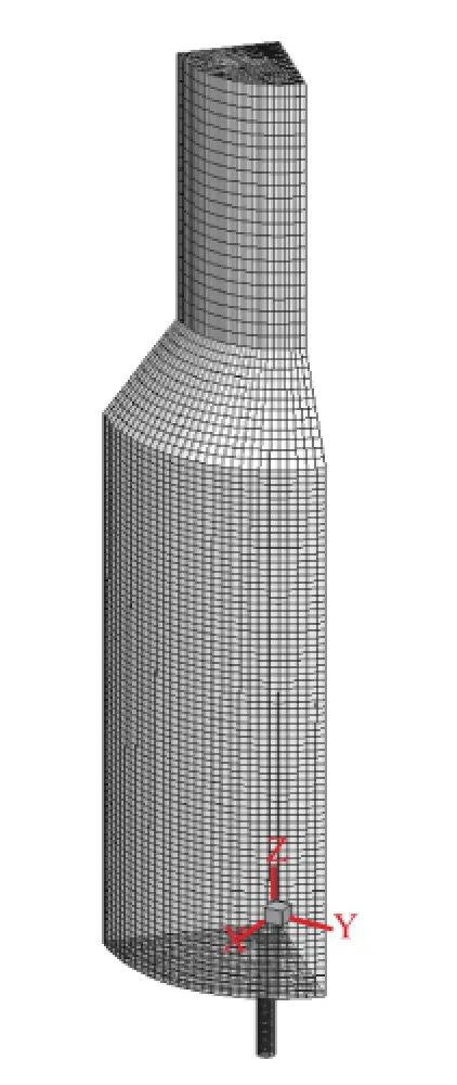
Figure 3 Grid of the furnace
Both air and fuel were assumed to obey the ideal gas law. Their specific heats were defined as a function of temperature. The Fick’s law with different diffusion coefficients by using molecular kinetic theory was used for computing the molecular diffusion in the species transport equations. The turbulence intensity at the inlet boundaries was 10%. The standard wall functions were employed for the near wall treatment. The relationship between the velocity and pressure corrections was solved by theSIMPLE algorithm. The second order upwind scheme was used for discretizing the convection terms, and the second order central-difference scheme was used for discretizing the diffusion terms in the transport equations. A pressure based steady-state segregated implicit solver was adopted. The numerical simulation was performed using the commercial CFD code FLUENT V6.3, which adopted the fi nite volume method.
Two convergence criteria were employed to determine the end of every numerical simulation. The fi rst criterion was to obtain an asymptotic behavior of governing equations’residuals. The maximal residuals of the energy, radiation and NO equations were less than 10-6and the residuals for all other variables were less than 10-3. The second criterion was to examine the mass and energy balance. Until the differences in the mass and energy balance were less than 1×10⁻⁷g/s and 10 W respectively, iterations of the governing equations were carried out.
3 Results and Discussion
3.1 Veri fi cation of the model
Before starting the study, we reproduced the conditions and the protocol presented in the references[19-20]. The excess air coef fi cient was 2.0, and therefore the inlet air mass fl ow rate was 6.9 g/s. The air preheating temperature was 773 K. All the other boundary conditions were consistent with the pro fi les depicted in Table 1.
Figure 4 shows the radial distribution of the temperature and the O2mole fraction at the sections located beyond a distance ofz=30, 90, 150, 210, and 270 mm from the burner exit. Figure 5 shows the radial distribution of the CO2and CO mole fractions at the same sections. Generally speaking, there were no significant differences between the predicted results and the measurements, apart from the near-burner region where the predictions underestimated the temperature and the CO2concentration, but overestimated the O2mole fraction. The predicted CO mole fractions showed discrepancies in comparison with the measurements. The discrepancies mainly existed at the furnace downstream such asz=210 mm and 270 mm where the reactions mainly occurred. However, the present predictions were in good agreement with the experimental data atz=30 mm and 90 mm where the recirculating fl ue gas dominated. That is to say, the CO emission in the fl ue gas can be predicted correctly. Figure 6 shows the predicted and measured radial pro fi les of the NO species. In general, the currently calculated NO concentrations are in good agreement with the measurements apart from the section located at a distance ofz=270 mm. Therefore, the present model can predict the NO concentration in the fl ue gas correctly. It is worth noting that there is always a discrepancy in the CO and NO predictions in the literature. The present predictions are better than those reported by Rebola, et al. especially in respect to the CO and NO concentrations. This may occur because, fi rstly, the thermal and molecular diffusions are considered in the present study which has a considerable effect on the accuracy of numerical modelling of mild combustion[27]; and secondly, the NO models for thermal and N2O-intermediate routes (e.g., the calculation of O and OH radical concentrations and the turbulent fl uctuations on mean reaction rates) are different. Different options may be the reason leading to differences in the predictions.
3.2 Flow and combustion characteristics
Figure 7 shows the flow field and temperature distribution in thexzplane of Run 3. The black line is the contour ofvz=0. There is a large recirculation zone (vz<0) in the furnace because the flue gas is entrained by the air jet. The reactants are diluted by the fl ue gas, the combustion is suppressed, and the peak fl ame temperature is reduced. It is beneficial to the establishment of mild combustion regime for suppressing the NOxformation. The temperature distribution is very uniform and the low temperature region is at the center of the furnace chamber because of the burner jet of cold air and methane. The peak flame temperature (Tmax) is 1 687 K, which is less than 1 800 K. As a result, the thermal NO formation is suppressed.
Figure 8 shows the H2CO and OH mole fraction fi elds in thexzplane of Run 3. The formaldehyde (H2CO) is an important first-step intermediate species formed in the low temperature region of hydrocarbons combustion and is known as the ignition marker[28-29]. In this mild combustion furnace, the H2CO mainly exists in the jet-mixing and pre-reaction zone. The OH radical concentration often represents the reaction rate and is a trustworthy marker of the reaction zone[18,28-29]. In this furnace, the jet velocityof the reactants is high and the reactants are diluted by the recirculated flue gas. Therefore, the OH species are mainly distributed in the downstream and in the outside region of the central jet fl ow.
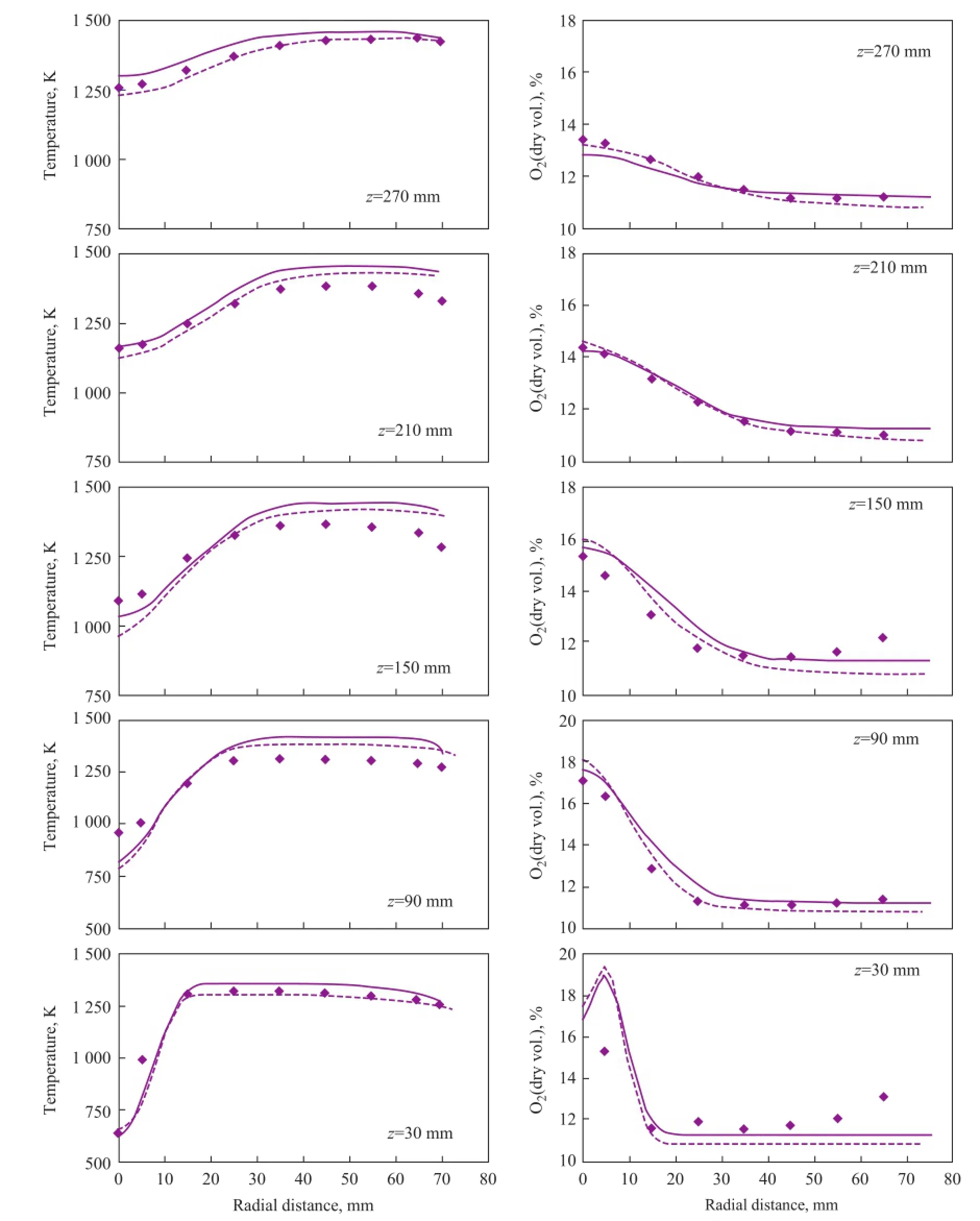
Figure 4 Calculated and measured radial temperature and O2molar fraction pro fi les
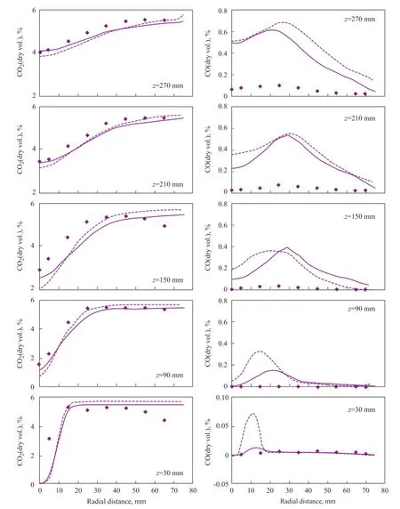
Figure 5 Calculated and measured radial CO2and CO molar fraction pro fi les
Cao, et al.[30]classi fi ed the mild combustion in a parallel jet furnace into three zones, namely: a central zone (I), a transition zone (II), and a recirculation zone (III), according to the distribution of NO and NO2species. In the present study, the mild combustion is classi fi ed based on the H2CO and OH distribution. Figure 9 shows the concentrations of H2CO and OH species along the furnace z axis of Run 3. There are four zones in the furnace: a central jet zone (a), an ignition zone (b), a combustion reaction zone (c), and a flue gas zone (d). The (a) zone is featured by high velocity and entrainment, where the reactant temperature increases upon being preheated by the recirculatedfl ue gas. When the reactant temperature is above its local auto-ignition point, the H2CO concentration increases and this is named the ignition zone. Then the OH concentration increases rapidly in the (c) zone, indicating that the combustion reaction occurs. The combustion products at high temperature are recirculated in the furnace or discharged through the stack to the atmosphere.
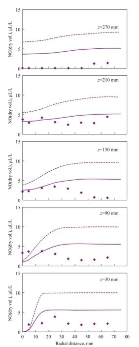
Figure 6 Calculated and measured radial NO pro fi les
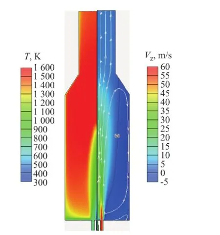
Figure 7 Temperature and z component of mean velocity (vz) fi elds in the xz plane of Run 3
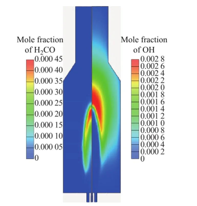
Figure 8 H2CO and OH mole fraction fi elds in the xz plane of Run 3
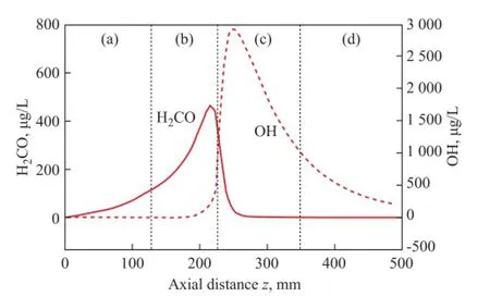
Figure 9 H2CO and OH concentration along the z axis of Run 3
3.3 Effect of air nozzle circle (D)
Figure 10 shows the effect of air nozzle circle (D) on the flow and combustion characteristics along the furnacezaxis of Runs 1 to 5. In these runs, the inlet methane velocity is 25.4 m/s and the inlet air velocity is 56.3 m/s. Runs 2 and 4 are not plotted here for brevity purpose. In Figure 10, thevzdecreases fi rstly due to the entrainment of fl ue gas by the methane jet. Then thevzincreases due to the entrainment by the air jet. Finally thevzdecreases gently. With the increase ofD, the decay ofvzis more evident in the upstream, because the central methane jet can entrain more fl ue gas before merging with the air jet. At a largerD, the in fl uence of the air jet on the central fl ow is weakened in the increased part ofvzbecause the con fl uent point of the methane and air jets is far apart from the burner exit. The difference among the runs is reduced after the con fl uence in the downstream. The temperature distribution in Figure 10 can be interpreted according to the gradient. The temperature increases fi rstly due to the entrainment of fl ue gas at high temperature (the fi rst part), and secondly due to mixing with the air jet and fl ue gas (the second part), and then thirdly due to the heat release of methane combustion (the third part). Finally the temperatures of all runs are similar afterz=250 mm (the fourth part). The gradient of temperature is smaller in the second part than the fi rst part. This occurs because the inlet air temperature is lower than the fl ue gas. Therefore with the increase ofD, the central methane jet can entrain more fl ue gas and its temperature increases much higher. The entrained fl ue gas dilutes the reactants and suppresses the combustion intensity and, therefore, the temperature is lower at a largerDin the reaction zone (the third part). The O2and CO2concentrations are expressed by volume on a dry basis in this study. The CO2and O2concentration indicates the entrainment of fl ue gas and the in fl uence of air jet, respectively. In general, the effect ofDon the fl ow and combustion characteristics is mainly in the upstream (z<250) and the effect is negligible in the downstream (z>250).
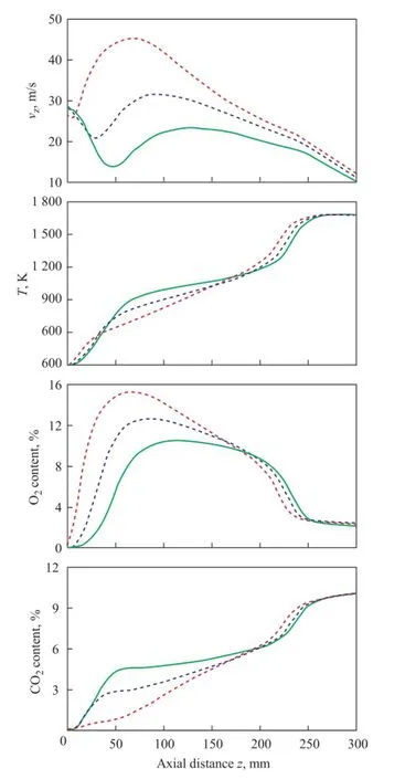
Figure 10 Effect of air nozzle circle (D) on the fl ow and combustion characteristics along the furnace z axis of Runs 1 to 5
Table 2 shows the effect ofDon the fl ue gas emissions at the radiant section outlet (z=300) and the furnace outlet of Runs 1 to 5. The O2, CO and NO emissions are expressed by volume on a dry basis in this study. The effect ofDon these predictions is insignificant. This conclusion is consistent with the pro fi les shown in Figure 10. The CO emission comprises the intermediate species resulted from hydrocarbons oxidation and its oxidation process is slower than other hydrocarbon reactions. In this forward flow furnace, the reactants can go through the radiant section easily, resulting in shorter residence time. Therefore the CO emission may quite be high enough[10,19]. In this study, the furnace wall temperature (1 173 K) is higher than the auto-ignition point of methane to intensify the oxidation process of CO and consequently the CO emission is low (less than 50 μL/L).

Table 2 Effect of air nozzle circle (D) on the flue gas emissions of Runs 1 to 5
In the 5 runs, all peak fl ame temperatures are less than 1 700 K that can suppress the thermal NO formation so that the NO emission is less than 8 μL/L.
3.4 Effect of air nozzle diameter (d)
Figure 11 shows the effect of air nozzle diameter (d) on the fl ow and combustion characteristics along the furnacezaxis of Runs 6 to 10. In these runs,dis increased from 5 mm to 9 mm and the inlet air velocity is decreased from 111 m/s to 33 m/s, correspondingly. In Figure 11, thevzdecreases fi rstly, because the central methane jet entrains the fl ue gas. Then thevzincreases, because the central jet is entrained by the air jet at high velocity. At a smallerd, the inlet air velocity is higher and, thus, thevzincreases remarkably. Finally, thevzdecreases in the downstream. The temperature increases sharply at first and then increases slowly along the furnacezaxis. The air jet with higher velocity can entrain more high-temperature flue gas and therefore the axis temperature is higher. At the downstream (z>230 mm), the combustion reaction occurs and the temperature is mainly determined by the heat release intensity achieved by the methane oxidation. Since more fl ue gas is entrained by the air jet with smaller diameter, the reactant mixture is diluted, and the downstream combustion intensity is suppressed, leading to a lower temperature. The O2and CO2concentrations along thezaxis can indicate the mixing performance of methane, air and flue gas. With the increase ofd, the air jet entrains less fl ue gas and thereby the CO2concentration is lower and the O2concentration is higher. In general, the effect ofdon the fl ow and temperature pro fi les is related with the performance of whole furnace while the effect on the O2and CO2concentrations is mainly related with the performance of the radiant section (z< 250 mm).
The effect ofdon the flue gas emissions at the radiant section outlet (z=300) and the furnace outlet of Runs 6 to 10 is shown in Table 3. The peak fl ame temperature (Tmax) decreases with a decreasingd, because the reactants are diluted by the flue gas so that the combustion reactions are suppressed. TheTatz=300 and at the furnace outlet both decreases as illustrated in Table 3 and Figure 11. Therefore more heat is absorbed in the radiant section and less heat is discharged to the atmosphere. Atz=300, the O2and CO concentrations both decrease with an increasingd, because the residence time is longer. The effect ofdon the O2and CO concentrations at the furnace outlet is negligible. The NO emission is low and decreases succes-sively with a decreasingd. At a smallerd, the combustion intensity is suppressed by the dilution of fl ue gas and the NO formation is also suppressed.

Table 3 Effect of air nozzle diameter (d) on the flue gas emissions of Runs 6 to 10
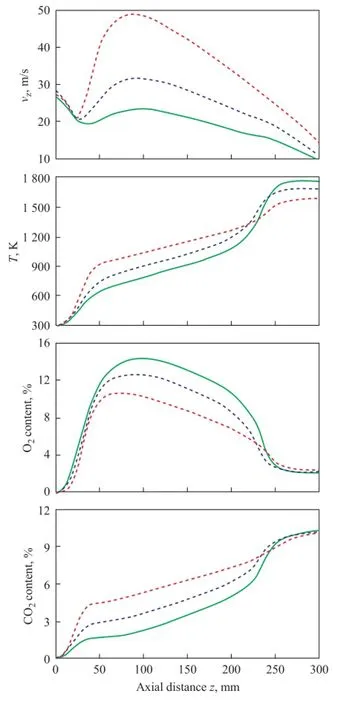
Figure 11 Effect of air nozzle diameter (d) on the fl ow and combustion characteristics along the furnacezaxis of Runs 6 to 10
3.5 Effect of air nozzle number(N)
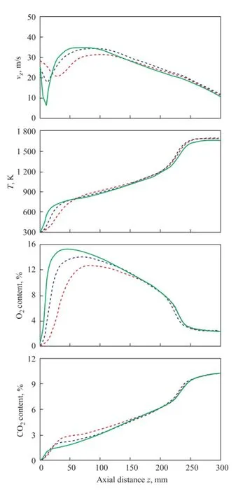
Figure 12 Effect of air nozzle number(N)on the flow and combustion characteristics along the furnace z axis of Runs 11 to 15
The effect of air nozzle number (N) on the fl ow and combustion characteristics along the furnace z axis of Runs 11 to 15 is shown in Figure 12.Nis increased from 4 to 12 when the air nozzle diameter (d) is decreased from 7 mm to 4 mm, correspondingly. The total area of air nozzles is maintained to have a constant velocity of air jet. With the increase ofN, the central methane jet is surrounded more compactly and has less space for the fl ue gas. The impact of the air jet on the axis pro fi les is enhanced and the impact of the fl ue gas is weakened. The methane is entrained by the air jet due to its smaller momentum. Therefore thevzdecays more sharply with the increase ofN. Then thevzalso increases more sharply asNincreases. Atz<55 mm, theTincreases from 293 K to 773 K approximately. TheTincreases more sharply with an increasingN, because the mixing process between the air and the methane is enhanced near the burner exit. The O2concentration along thezaxis also indicates a better mixing between the air and the methane near the burner exit. The flue gas has less effect on the axis pro fi les with the increase ofN, as evidenced by the CO2concentration. In general, the effect ofNis mainly identi fi ed in the furnace upstream and is insigni fi cant in the downstream.
Table 4 shows the effect ofNon the fl ue gas emissions of Runs 11 to 15. AsNis increased from 4 to 12, the air jet is distributed to cover a larger region and also the reaction zone with a larger area. The combustion heat is spread further and the peak flame temperature is reduced. TheTpredicted thereby at the radiant section outlet (z=300) and the furnace outlet both decreases with the increase ofN. Therefore more heat is absorbed in the radiant section and less heat is discharged to the atmosphere. The CO emission is low and the effect ofNon it would be insignificant. The NO emission also decreases slightly with an increasingN, because the combustion intensity is suppressed (lowerTmax).

Table 4 Effect of air nozzle number (N) on the flue gas emissions of Runs 11 to 15
3.6 Effect of air preheating temperature (Tair)
Figure 13 shows the effect of air preheating temperature (Tair) on the flow and combustion characteristics along the furnacezaxis of Run 10. TheTairranges from 373 K to 773 K according to the operating conditions of tube furnace. The inlet air velocity is increased from 16.1 m/s to 33.3 m/s, correspondingly. The decay ofvzis less affected byTairnear the burner exit. Atz>75 mm, the central methane is entrained more strongly andvzis higher with an increasingTairand the inlet air velocity. The process for mixing methane and air is enhanced and the combustion reaction is intensi fi ed. Therefore, the axis temperature is higher and can reach a highest level of fl ame temperature earlier at a higherTair. The O2concentration near the burner exit is slightly higher, indicating to better mixing between the methane and air. The O2concentration in the downstream is lower, indicating that it is consumed rapidly and the CO2concentration is higher, denoting that the combustion is intensi fi ed. At lowerTair, the inlet air velocity is smaller and the mixing process is suppressed. The combustion reaction zone is extended beyond the chamber as illustrated by the axisT, O2, and CO2pro fi les.
Table 5 shows the effect ofTairon the fl ue gas emissions of Run 10. With an increasingTair, the fl ue gas temperature atz=300 increases, which is consistent with curves shown in Figure 13. Since more heat with air is supplied to the furnace, the flue gas temperatures at the outlet increases. TheTmaxincreases because the combustion is enhanced and the NO emission is also increased. In this study, the residence time of flue gas in the small-scale furnace is less. On the other hand, the reactants can go through the radiant section and can be discharged to the atmosphere. The CO emission measured at the radiant section outlet (z=300) decreases with the increase ofTair. This conclusion is consistent with the results obtained by Rebola, et al.[19]However, the CO emission at the furnace outlet is low and is less affected byTair. This means that the residence time from the burner exit to the furnace outlet is suf fi cient for the oxidation of CO.

Table 5 Effect of air preheating temperature (Tair) on the flue gas emissions of Run 10
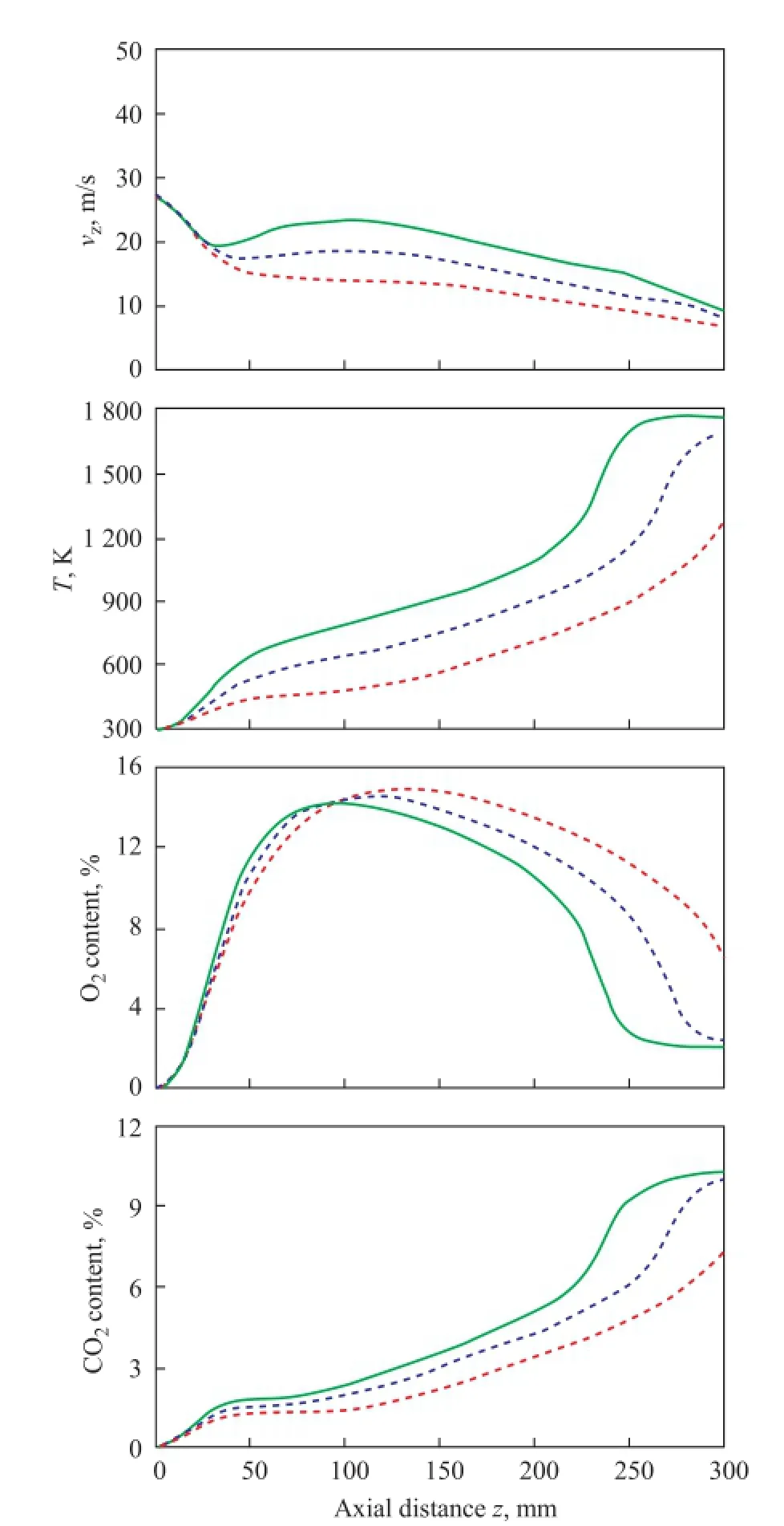
Figure 13 Effect of air preheating temperature (Tair) on the fl ow and combustion characteristics along the furnace z axis of Run 10
4 Conclusions
Numerical simulations were carried out to investigate the performance of a forward fl ow furnace. A level of con fidence in the present model setup was established by validation against measurements. The effects of the air nozzle circle (D), air nozzle diameter (d), air nozzle number (N), and air preheating temperature (Tair) on the fl ow, temperature and species fields, and the CO and NO emissions were analyzed, from which the following conclusions could be drawn:
According to the distribution of H2CO and OH, there are four zones in the furnace, viz.: a central jet zone, an ignition zone, a combustion reaction zone, and a fl ue gas zone. The central methane jet is preheated and diluted by the entrained fl ue gas. The axis velocity is increased due to the high velocity of air jet.
The effect of air nozzle circle (D) on the fl ow and combustion characteristics of the mild combustion furnace is mainly identi fi ed in the furnace upstream and the effect is negligible in the downstream. More fl ue gas is entrained by the central jet asDincreases.
When the air nozzle diameter (d) is reduced, the air jet momentum is increased. The air entrains more flue gas and increases the axis velocity. The temperature at the radiant section outlet and the furnace outlet is decreased, indicating that more heat is absorbed in the radiant section and less heat is discharged to the atmosphere.
The effect of the air nozzle number (N) is mainly identifi ed near the burner exit when the nozzles’ area is maintained constant. As N increases, the combustion zone is enlarged and the peak fl ame temperature is reduced. The fl ue gas temperature at the radiant section outlet and the furnace outlet is decreased. The NO emission is also de-creased slightly.
The combustion is enhanced at higher air preheating temperature (Tair). The CO emission is low and is less affected byTair,because the residence time from the burner exit to the furnace outlet is suf fi cient for the oxidation of CO.
Acknowledgements: This work was gratefully supported by the technology development fund of China Petroleum & Chemical Corporation (Sinopec 312016 and 314054).
[1] Skalska K, Miller J S, Ledakowicz S. Trends in NOxabatement: A review [J]. Science of the Total Environment, 2010, 408(19): 3976-3989
[2] Ballester J M, Dopazo C, Fueyo N, et al. Investigation of low-NOxstrategies for natural gas combustion [J]. Fuel, 1997, 76(5): 435-446
[3] Gómez-García M A, Pitchon V, Kiennemann A. Pollution by nitrogen oxides: An approach to NOxabatement by using sorbing catalytic materials [J]. Environment International, 2005, 31(3): 445-467
[4] Wünning J A, Wünning J G. Flameless oxidation to reduce thermal NO-formation [J]. Progress in Energy and Combustion Science, 1997, 23(1): 81-94
[5] Nishimura M, Suzuki T, Nakanishi R, et al. Low-NOxcombustion under high preheated air temperature condition in an industrial furnace [J]. Energy Conversion and Management, 1997, 38(10/13): 1353-1363
[6] Arghode V K, Gupta A K. Development of high intensity CDC combustor for gas turbine engines [J]. Applied Energy, 2011, 88(3): 963-973
[7] Cavaliere A, De Joannon M. Mild combustion [J]. Progress in Energy and Combustion Science, 2004, 30(4): 329-366
[8] Li P F, Mi J C, Dally B, et al. Progress and recent trend in MILD combustion [J]. Science China Technological Sciences, 2011, 54(2): 255-269
[9] Arghode V K, Gupta A K. Investigation of reverse fl ow distributed combustion for gas turbine application [J]. Applied Energy, 2011, 88(4): 1096-1104
[10] Arghode V K, Gupta A K. Investigation of forward fl ow distributed combustion for gas turbine application [J]. Applied Energy, 2011, 88(1): 29-40
[11] Tu Y J, Liu H, Chen S, et al. Effects of furnace chamber shape on the MILD combustion of natural gas [J]. Applied Thermal Engineering, 2015, 76: 64-75
[12] Huang M M, Zhang Z D, Shao W W, et al. Coal-derived syngas MILD combustion in parallel jet forward fl ow combustor [J]. Applied Thermal Engineering, 2014, 71(1): 161-168
[13] Huang M M, Zhang Z D, Shao W W, et al. Effect of air preheat temperature on the MILD combustion of syngas [J]. Energy Conversion and Management, 2014, 86: 356-364
[14] Huang M M, Shao W W, Xiong Y, et al. Effect of fuel injection velocity on MILD combustion of syngas in axiallystaged combustor [J]. Applied Thermal Engineering, 2014, 66(1/2): 485-492
[15] Gu M Y, Chen G, Liu X H, et al. Numerical simulation of slab heating process in a regenerative walking beam reheating furnace [J]. International Journal of Heat and Mass Transfer, 2014, 76: 405-410
[16] Zhou X F, Yang Y Y, Wang G Q, et al. Estimating the operation status of ethylene cracking furnace using numerical simulation with combustion models [J]. China Petroleum Processing & Petrochemical Technology, 2012, 14(4): 52-63
[17] Li Wenhui, Ma Weiyuan, Bai Wenkang. Application prospects of regenerative combustion technology in tube furnace in petrochemical industry [J]. Petro-Chemical Equipment Technology, 2011, 32(6): 50-53. (in Chinese)
[18] Ayoub M, Rottier C, Carpentier S, et al. An experimental study of mild fl ameless combustion of methane/hydrogen mixtures [J]. International Journal of Hydrogen Energy, 2012, 37(8): 6912-6921
[19] Rebola A, Costa M, Coelho P J. Experimental evaluation of the performance of a fl ameless combustor [J]. Applied Thermal Engineering, 2013, 50(1): 805-815
[20] Rebola A, Coelho P J, Costa M. Assessment of the performance of several turbulence and combustion models in the numerical simulation of a fl ameless combustor [J]. Combustion Science and Technology, 2012, 185(4): 600-626
[21] Lupant D, Lybaert P. Assessment of the EDC combustion model in MILD conditions with in-furnace experimental data [J]. Applied Thermal Engineering, 2015, 75: 93-102
[22] Kazakov A, Frenklach M. Reduced reaction sets based on GRI-Mech 1.2. http://combustion.berkeley.edu/drm/
[23] Pope S B, Computationally efficient implementation of combustion chemistry using in situ adaptive tabulation [J]. Combustion Theory and Modelling, 1997, 1(1): 41-63
[24] Smith T F, Shen Z F, Friedman J N. Evaluation of coef ficients for the weighted sum of gray gases model [J]. Journal of Heat Transfer, 1982, 104(4): 602-608
[25] Vascellari M, Cau G. Influence of turbulence–chemical interaction on CFD pulverized coal MILD combustion modeling [J]. Fuel, 2012, 101: 90-101
[26] De Soete G G, Overall reaction rates of NO and N2formation from fuel nitrogen [J]. Symposium (International) onCombustion, 1975, 15(1): 1093-1102
[27] Mardani A, Tabejamaat S, Ghamari M. Numerical study of influence of molecular diffusion in the Mild combustion regime [J]. Combustion Theory and Modelling, 2010, 14(5): 747-774
[28] Afarin Y, Tabejamaat S. Effect of hydrogen on H2/CH4fl ame structure of MILD combustion using the LES method [J]. International Journal of Hydrogen Energy, 2013, 38(8): 3447-3458
[29] Mei Z F, Wang F F, Li P F, et al. Diffusion fl ame of a CH4/ H2jet in a hot co fl ow: effects of co fl ow oxygen and temperature [J]. Chinese Journal of Chemical Engineering, 2013, 21(7): 787-799
[30] Cao S Y, Zou C, Han Q S, et al. Numerical and experimental studies of NO formation mechanisms under methane Moderate or Intense Low-Oxygen Dilution (MILD) combustion without heated air [J]. Energy & Fuels, 2015, 29(3): 1987-1996
Received date: 2015-07-06; Accepted date: 2015-12-10.
Dr. Wang Yuanhua, Telephone: +86-21-64251315; Fax: +86-21-64253810; E-mail: jswyuanhua@ ecust.edu.cn.
- 中國煉油與石油化工的其它文章
- Molecular Simulations of FCC Dry Gas Components Adsorption in Zeolite Y1
- Intrinsic Kinetic Modeling of Thermal Dimerization of C5Fraction
- Synthesis and Properties of Dendritic Long-Chain Esters as Crude Oil Flow Improver Additives
- Method for Control of Particle Size and Morphology of Paraf fi n/Polystyrene-Divinylbenzene Microcapsules
- Study on Absorption and Regeneration Performance of Novel Hybrid Solutions for CO2Capture
- Linkage of Aromatic Ring Structures in Saturates, Aromatics, Resins and Asphaltenes Fractions of Vacuum Residues Determined by Collision-Induced Dissociation Technology

