
Analysis of fretting wear behavior of unloading valve of gasoline direct injection high-pressure pump
2022-05-10 10:07:50LiangLUYinpengXUMengruLIQilongXUEManyiZHANGLiangliangLIUZhongyuWU
Liang LU ,Yin-peng XU ,Meng-ru LI? ,Qi-long XUE ,Man-yi ZHANG ,Liang-liang LIU ,Zhong-yu WU
1School of Mechanical Engineering,Tongji University,Shanghai 201804,China
2State Key Laboratory of Fluid Power&Mechatronic Systems,Zhejiang University,Hangzhou 310027,China
3United Automotive Electronic Systems Co.,Ltd.,Shanghai 200120,China
4Frontiers Science Center for Intelligent Autonomous Systems,Shanghai 201210,China
Abstract:The high pressures in gasoline direct injection technology lead to structural damage in some hydraulic components,especially annular damage on the contact area of the valve ball and on the valve seat of the spherical unloading valve in the high-pressure pump.In previous study,the authors have analyzed the damage on the unloading valve and demonstrated that it is caused neither by static damage nor fatigue damage and have put forward the hypothesis of fretting wear.This paper is based on the establishment of the statically indeterminate structure of the unloading valve.The micro friction parameters (stress,friction coefficient,etc.) required for the numerical iterative calculation of fretting wear are calculated.In addition,based on the grid adaptive technology and a modified Archard wear model,the fretting wear is calculated quantitatively and is in good agreement with experimental results.Based on that verification,the wear laws of the valve ball and valve seat under the same hardness,different contact angles,and different assembly stresses,are analyzed in detail,and reasoned suggestions for the structural design and assembly design of the ball valve are given.
Key words:Fretting wear behavior;Unloading valve;Experimental and numerical analyses;High pressure
1 Introduction
Compared with the traditional intake port injection gasoline engine,gasoline direct injection (GDI)technology can reduce fuel cost by 15%and hydrocarbon emission by 30%.Therefore,GDI technology has strong advantages in saving energy consumption and reducing exhaust pollution.High-pressure direct injection technology is one of the directions of development for direct injection vehicles (Zhao et al.,1999).The high-pressure fuel pump is the key to the whole highpressure fuel supply system.The spherical unloading valve,which will open and release high-pressure fuel when the fuel pressure in the high-pressure side of the system is too high,works as the safety valve in the high-pressure direct injection fuel supply system for automobiles.The spherical unloading valve plays a key role in building and maintaining the fuel pressure of the high-pressure fuel supply system.Responding to market demand for high-pressure direct injection systems,the fuel pressure of the high-pressure side of the spherical unloading valve is increased.Consequently,the maximum pressure of the low-pressure side is increased,which causes annular damage on the contact area of the valve ball and the valve seat.The damage causes a premature opening of the spherical valve when the fuel pressure of the high-pressure side is below 35 MPa.Thus,the pressure of the fuel supply system cannot be built and maintained effectively.The system cannot meet the requirements for normal work in respect either of security or of service life.
Facing the problems of noise,fuel injection and structural strength caused by high pressure,scholars in relevant industries have made targeted analysis and research.Borg et al.(2012) proposed a currentshaping technique and a pulse-skipping control strategy to reduce noise by up to 5 dB in the low-frequency and mid-frequency range and an injector suspension method to reduce noise in the high-frequency range of the gasoline direct injection system.Sharma et al.(2019) investigated the combustion,noise,and vibration characteristics of three oxygenated test fuels(M10,M20,and G100).The results showed that gasohol generates lesser vibration and noise,which makes them suitable for use as oxygenated fuels and for partial replacement of conventional petroleum-based fossil fuels such as gasoline.Liu et al.(2021) built a test platform for ethanol port injection plus gasoline direct injection to explore the effects on the combustion and emissions of a spark ignition (SI) engine.Results clearly show that when the total fuel contains more ethanol,the ignition timing corresponding to the maximum torque is smaller than the ignition timing when the total fuel contains more gasoline.Qian et al.(2019)investigated the effects of combustion system parameters on the scavenging process and proposed an optimum structural shape for the combustion chamber.At present,however,there are few targeted studies on the structural damage of the various components in the high-pressure oil supply system.In this paper,the structural damage of the high-pressure pump unloading valve is analyzed.According to preliminary analysis,it is considered that the damage is caused by fretting wear(Lu et al.,2019).
Friction problems of hydraulic fluid control components have always been an important research topic.Scholars have done much research on hydraulic pumps,hydraulic slide valves,and other components.Yin et al.(2017)developed a numerical model for predicting the removal rate of corrosive material and the profile evolution of wear in hydraulic spool valves and discussed the main influencing factors,including grain size,differential pressure,reel opening,and flow direction.Their model was validated by comparison with laboratory experiments and field cases.The design and optimization of the key friction pairs are always key and difficult problems in research on the axial piston pump.Xu et al.(2012,2013)established a simulation model based on oil film lubrication theory,analyzed the dynamic characteristics and pressure distribution of radial fretting,and discussed the relationship between radial fretting and bearing capacity,lubrication conditions,and wear.For the high wear rate and rapid loss of the surface modification layer of the piston/cylinder pair in axial piston pumps,Zhang et al.(2021) built a wear degradation model to obtain the variation in wear of the piston/cylinder pair with the operating time.The wear contour at the lowest wear rate was derived to guide the design of a pre-machined surface contour.In addition,additive manufacturing not only provides a new way to manufacture the products with complex internal channels,but also indicates a design revolution for existing products with regular internal channels that are currently limited by conventional fabrication methods (Zhang et al.,2020).For the poor fabricating quality caused by residual stress on the large overhang region when using one type of metal additive manufacturing technology—selective laser melting (SLM),Zhou et al.(2020) developed a new friction factor model to calculate pressure loss in a SLM fabricated channels.The friction loss of the laser powder bed fusion (L-PBF) fabricated fluid channels is greatly affected by the fabrication quality but remains unknown.Zhou et al.(2021)developed a comprehensive model to predict friction factors of the L-PBF fabricated fluid channels and proposed design guidelines of fluid channels by considering both fabrication quality and friction factors.
Most of the early research on fretting wear was at the level of qualitative understanding.However,since the 1990s,quantitative experimental and simulation research on fretting wear has increased.Goryacheva et al.(2001) developed the analysis technology for the purely contact based wear problem and proposed an analysis method to simulate the fretting wear under the condition of partial sliding in 2D sliding.In this model,the Archard equation was applied to evaluate the wear in one cycle and the distance change in the sliding region.Then an iterative program was used to calculate the change of contact characteristics with the increase of wear cycles.To solve this kind of problem Johansson (1994) proposed a finite element method combined with the Archard equation to evaluate the changes of contact geometry and related contact pressure.?qvist (2001) proposed a numerical simulation study of the slight wear between the cylindrical steel roll and the steel plate in the reciprocating contact fit,obtained the simulation results of the wear profile,and established a good correlation between the numerical prediction and the experimentally measured wear profile over approximately one million cycles.Experiments on fretting wear are very costly,time-consuming,and laborious.The idea of finite element simulation provides a new approach of low cost and easily controlled parameter variables and boundary conditions for the study of fretting wear.The finite element method can provide corresponding research methods for different research objects.In recent years,many scholars have carried out wear research in the fields of car body,car wheel,and bionics (Jia et al.,2020;Sun and Xu,2020;Tao et al.,2021).In this paper,the finite element simulation software ABAQUS is used to study the fretting wear of the unloading valve,to seek the optimal parameters for the improvement of the anti-wear structure,and to provide a new solution to the structural problems caused by the high pressure of the automobile oil supply system.
This paper is organized as follows.First,the statically indeterminate structure of the unloading valve is analyzed to acquire the essential parameters that would be needed in simulation.Because previous research has proved that the damage of the unloading valve is neither caused by static damage nor fatigue damage but by fretting wear (Lu et al.,2019),experiments to obtain the fretting wear characteristics of the unloading valve are conducted.To quantitatively calculate the wear amount of fretting wear by simulation,a modified Archard model is used together with the adaptive grid technology.A set of comparison results between simulation and experiment verify the rationality of the simulation modeling.Finally,the influence of the contact angle and the assembly stress is discussed in detail to study the law of fretting wear of the unloading valve.
2 Model and experiment
2.1 Principle of the unloading valve
This paper concerns the spherical unloading valve in the high-pressure pump of a direct injection vehicle.The working principle of the high-pressure pump is shown in Fig.1.With the rotation of the cam,the piston rod of the oil cylinder moves downward,and the flow control valve controls the switch to the oneway valve to suck oil from the low-pressure end.With the upward movement of the piston rod,the oil cylinder supplies oil to the high-pressure end.The spherical unloading valve is an important part of the highpressure pump of a direct injection vehicle.As a safety valve,the unloading valve plays a role in building and maintaining the pressure.When the pressure at the high-pressure end is too high,it can release the oil,thus ensuring the normal operation of the whole highpressure pump.
Fig.2 shows the structure and force state of the valve,wheref
represents the friction between valve ball and valve seat,N
represents the normal pressure between valve ball and valve seat,andF
represents the equivalent force of pressurep
.The valve is stressed with an alternating pressurep
of 0 to 45 MPa from the left side and a constant pressure ofp
from the right side.The valve is also initially stressed with a preload of the spring from the left side.When the pressure difference exceeds the preload of the spring,the spherical valve opens and high-pressure oil from the right-side flows to the left side to unload.Table 1 shows the structural parameters of the valve and oil pressure parameters.The contact area of the valve ball and valve seat is under an equivalent pressure of 5 to 50 MPa.Table 1 Parameters of structure and oil pressure
2.2 Experiment design
According to the above hydraulic principle and force state of the unloading valve,experiments were designed to study the fretting wear characteristics of the unloading valve.The contact area between the valve ball and the valve seat receives an alternating pressure of 5-50 MPa,which can be equivalent to a loading force of 6.90-78.75 N.To provide a high frequency alternating force,a piezoelectric ceramic was used as the key component of the experiment device.For the loading scheme of piezoelectric ceramics,the following factors need to be considered in the design process:
(a)The unloading valve needs to be fixed during the experiment.
(b)It is necessary to accurately locate and fix the relative position of piezoelectric ceramics and the unloading valve,so as to ensure the accuracy of rigid deformation on the force loading of the unloading valve.
(c) A micro pressure sensor needs to be added between the piezoelectric ceramic and the unloading valve in order to monitor the force state of the valve ball.
(d) The frequency demand of amplifier and data collector is very high,and needs to reach more than 20 times the loading frequency.
To simulate the oil immersion condition of the unloading valve,a transverse flow channel is set up in the lower part of the experimental device.Gasolinelike medium T16 is selected as the test medium,which can simulate the properties of gasoline well and has good aging and corrosion resistance.In addition,the test medium has good stability and is not as flammable and explosive as gasoline,so it can ensure the safety of the experiment.
The final experimental device composition is shown in Fig.3.The piezoelectric ceramics is connected with the flange plate and the upper base through the shell thread.The flange part is also fixed with the upper base through the four hollowed out strips.The connecting rod No.1,the force sensor,and the connecting rod No.2 are connected in turn to form a “sandwich” structure,and the tested ball valve is fixed through the groove on the lower base.The high frequency alternating load generated by the piezoelectric ceramics can be transmitted to the valve ball through the “sandwich” structure.In view of the heatdissipation problem of the driving power supply of the piezoelectric ceramics under the action of high frequency for a long time,it is necessary to design a heat dissipation channel in the power supply part,and the external ventilation and heat dissipation are carried out by an air compressor.The finally designed system is shown in Fig.4.
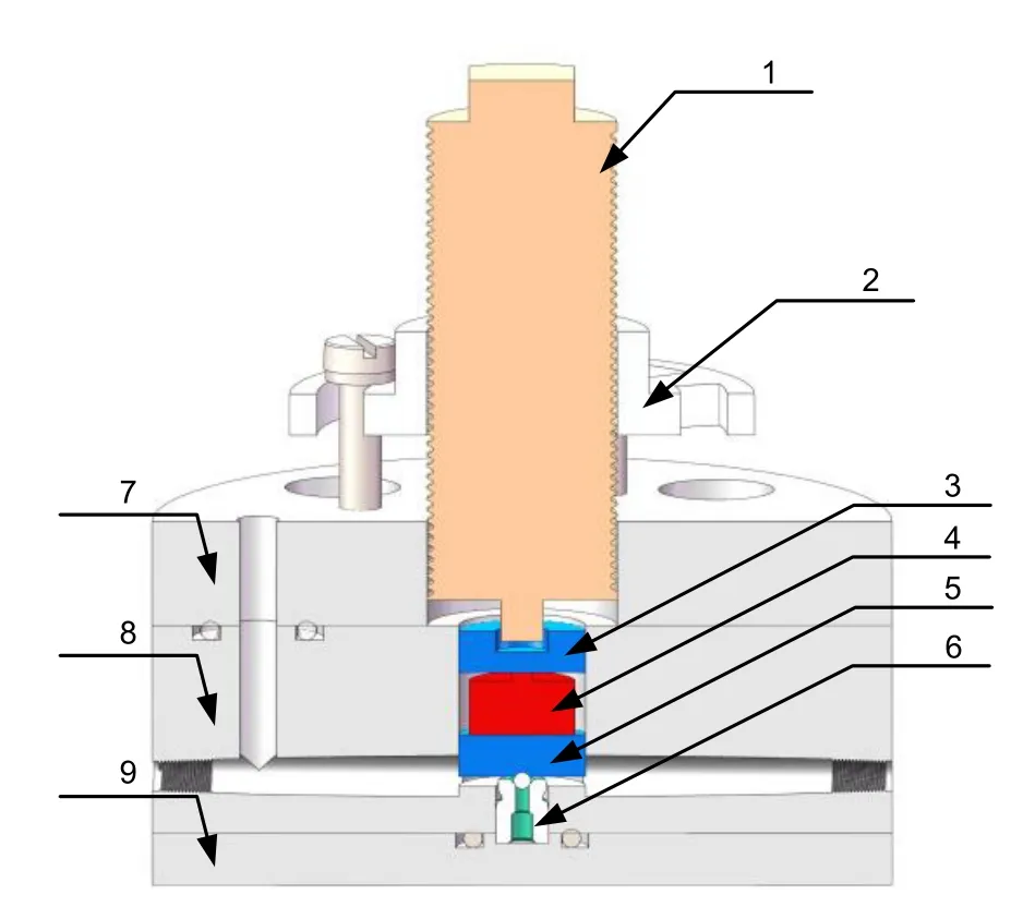
Fig.3 Final experiment device composition.1:piezoelectric ceramics;2:flange plate;3:connecting rod No.1;4:pressure sensor;5:connecting rod No.2;6:tested unloading valve;7-9:bases
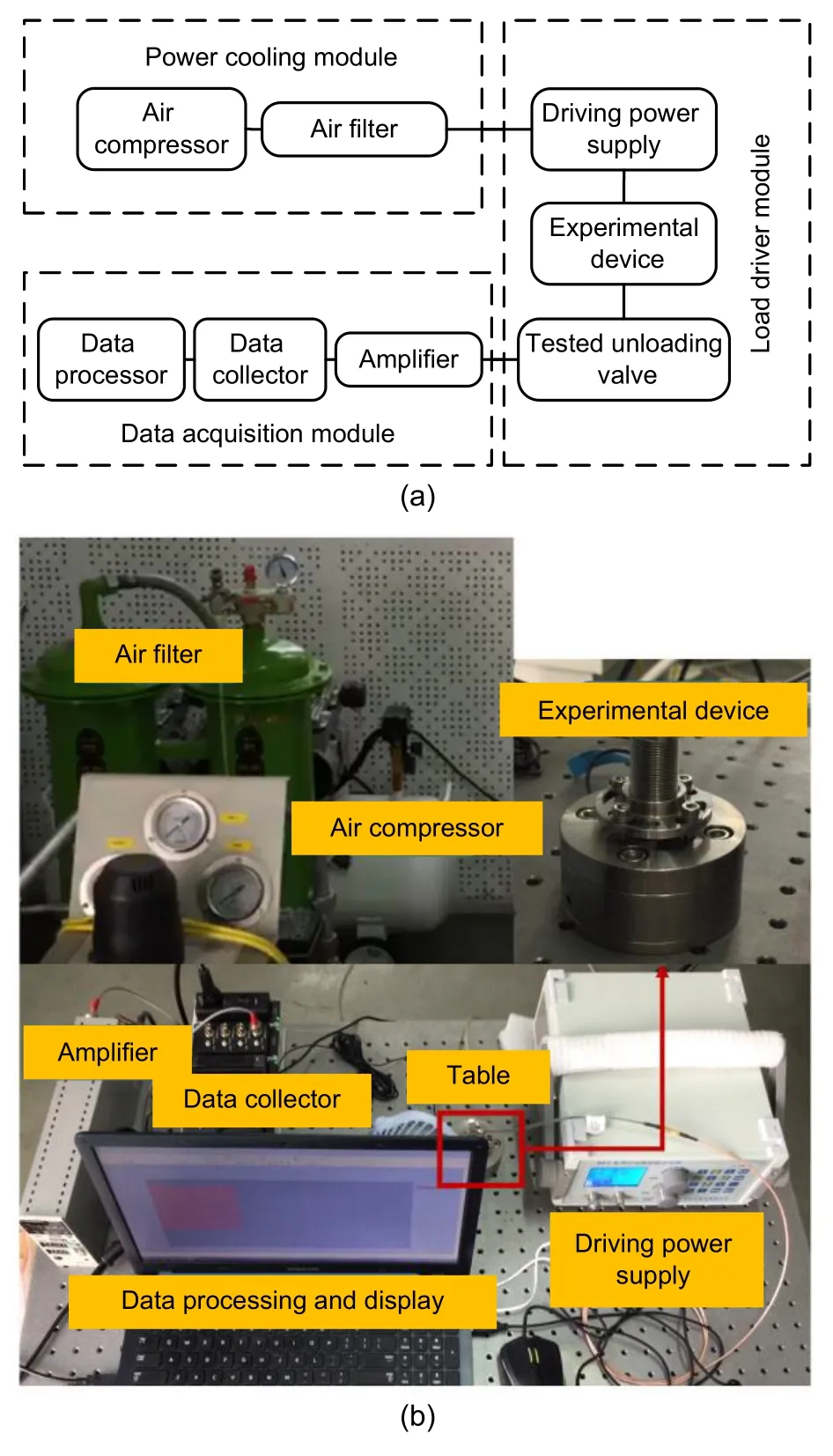
Fig.4 Sketch of the experiment system (a);photo of the experiment system(b)
2.3 Measurement of wear width
To compare the experimental data with the later simulation results,it is necessary to measure the wear width of the valve ball and valve seat after the fretting test.The measurement tool is a Leica optical microscope,which can directly measure and read the measurement results with an accuracy of 0.1 μm.The valve ball and valve seat need to be measured differently due to their different geometries.As for the valve seat,it can be directly installed on the fixture vertically in the axial direction.The observing direction of the microscope is also along the axial direction of the valve seat.Since the wear band is located on the sealing slope of the valve seat,it is necessary to convert the measurement data obtained from that direction.Let the width of the wear band obtained bes
′,and the actual wear band widths
can be obtained bys
=s
′/sinθ
.As for the valve ball,adding it to the fixture cannot 100% ensure that the wear band is facing the observing direction.Therefore,for the measurement of the wear width of the valve ball,it is necessary to take the average of multiple measurement results to eliminate human error.Fig.5 shows the schematic diagram of seat and ball wear width measurements.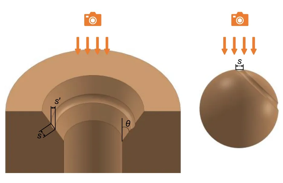
Fig.5 Schematic diagram of seat and ball wear width measurements
3 Simulation methodology
3.1 Theoretical analysis of the statically undetermined structure
According to the structure and force state of the valve,the valve ball and the valve seat are initially in line contact.To facilitate the analysis of the contact force,the structure of the valve is divided intom
equal divisions as shown in Fig.6.The force state of each micro-element is shown in Fig.7,where ΔF
,ΔN
,and Δf
respectively represent the equivalent pressure,the normal pressure,and the friction of the microelement.The force state can be described by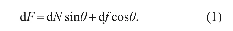
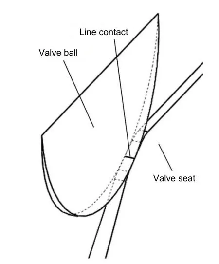
Fig.6 Micro-division of the structure(Lu et al.,2019)
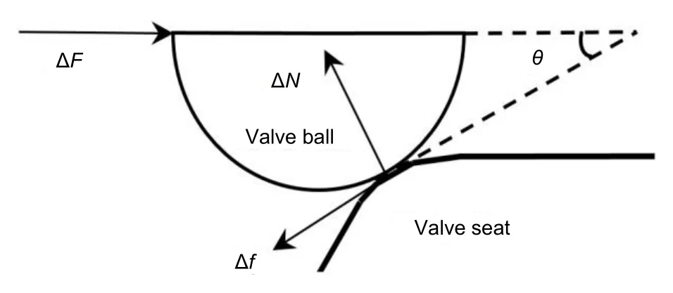
Fig.7 Force state of each micro-element(Lu et al.,2019)
The normal pressure dN
and friction df
cannot be directly solved by Eq.(1)alone since the force state is statically indeterminate.Therefore,more equations are needed as supplementary conditions.The equivalent friction coefficientμ
between two contact surfaces under static friction can be described as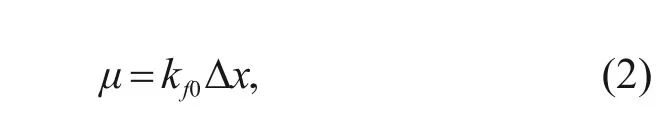
k
represents a constant value of the material;Δx
represents the micro-slip distance under static friction.The relationship between the normal pressure and friction acting on the micro-element can be described as follows:
r
represents the distance between the ball center and valve seat after the micro-slip happens;a
represents the halfwidth of contact between the valve ball and valve seat.Two equations can be concluded from the model as follows:
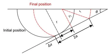
Fig.8 Micro-slip model of the micro-element
The half-width of contact can be solved by Hertz contact theory(Johnson,1985).Fig.9 shows the theoretical model given by Hertz contact theory for the distribution of contact stress on the contact area of two cylinders.The two cylindrical surfaces are in close contact due to the normal pressureP
.In this way,the contact area changes from line contact to surface contact.The shape of the contact stress distribution of the contact area is an ellipse.σ
represents the maximum contact pressure.The half-length of the major axis of the ellipse is the half-width of contacta
.The distribution of the contact stress can be described as follows: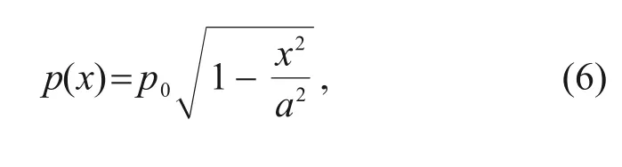
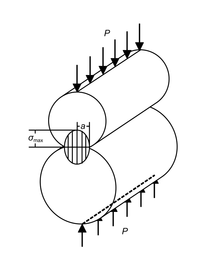
Fig.9 Hertz contact stress model
wherep
represents the maximum contact stress;x
represents the distance between a point on the contact surface and the initial contact point.The half-width of contact and the maximum contact stress can be described as follows: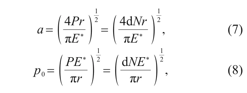
P
represents the line pressure on two cylinders(N/mm),which can be seen as the normal pressure on the micro-element;E
represents the equivalent elastic modulus,which can be described as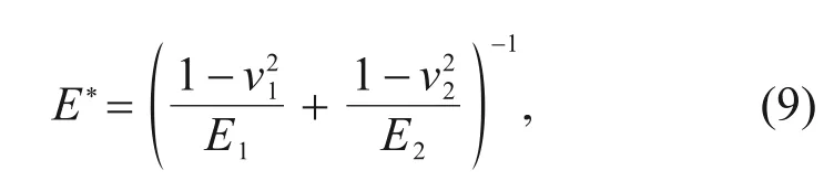
E
andE
represent the elastic moduli of two materials,andν
andν
represent Poisson’s ratios of the two materials,respectively.G
represents the relative curvature,which can be described as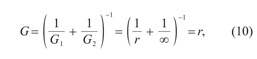
G
andG
respectively represent the relative radius of curvature of two cylinders.If one of the cylinders is changed into a flat,it can be regarded as a cylinder with infinite radius of curvature.Eqs.(1)-(10)are taken into consideration and all the known parameters are substituted in the above equations and give these results:the equivalent friction coefficientμ
=0.0887;the micro-slip distance Δx
=0.355 μm;the half-width of contacta
=17.15 μm;the maximum contact stressp
=1220 MPa.3.2 Archard’s wear model
According to the Archard equation,the wear volume of the material is directly proportional to the slip distance and positive pressure,but inversely proportional to the hardness of the material.The Archard equation for sliding wear is normally expressed as(Archard,1953):
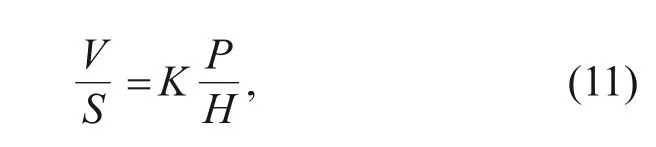
V
is the wear volume,S
is the sliding distance,H
is the hardness of the material,andK
is the wear coefficient.After its proposal in the 1950s,the Archard equation was immediately applied to the experimental study of fretting wear.At the same time,it was also applied to analytical and finite element simulation calculations.Fouvry (2001) proposed a simplified model based on the Archard equation using the Archard factor and the corresponding partial Archard factor density,in which the local Archard factor density describes the distribution of the Archard factor on the contact surface and is directly proportional to the wear depth.McColl et al.(2004) simulated and analyzed the conventional fretting wear device in a cylindrical plane based on the Archard wear model.They predicted the change of fretting contact surface profile with the number of cycles and studied in detail the influence of fretting wear on fretting fatigue.
In the finite element simulation,it is necessary to control the node coordinates of the contact surface and a wear model suitable for fretting wear is needed.However,Archard’s wear model was proposed based on macro wear,so it needs to be modified to be suitable for finite element simulation.In the finite element method,the macro object is divided into finite elements,which are composed of nodes,and then the macro object is simulated and analyzed by the finite element method.Each node represents a local location.If the applicability of the two wear models is extended from the macro object to the local position,the local node coordinates can be controlled scientifically,so as to characterize the wear of materials and realize the quantitative simulation of fretting wear.
In finite element simulation analysis,differentiating both sides of the Archard equation,we can obtain:
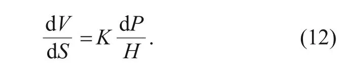
h
at each position,and set dh
(x
) as the wear depth at node positionx
.For a very small contact surface dA
,it is assumed that when the relative sliding distance of the contact surface is dS
,the wear depth of this part is dh
.Dividing the left and right sides of the equation by dA
at the same time: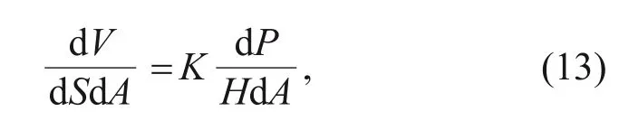
V
/dA
=dh
is the local wear depth,and dP
/dA
is the local contact compressive stressp
(x
)at positionx.
Eq.(13)can be expressed as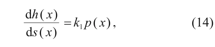
s
(x
) is the relative sliding distance at positionx
,andk
is the wear coefficient,k
=K
/H
.By transforming Eq.(14),the expression of wear depth at positionx
can be obtained:
s
(x
) occurs at positionx
.In the finite element simulation calculation,the action process of a cyclic load can be divided inton
increments,and in any incremental stepi
,the contact stressp
(x
) at positionx
remains unchanged,and the relative slip is Δs
(x
),where Δs
(x
)=s
(x
)-s
(x
),ands
(x
)ands
(x
)are the corresponding sliding distances at thei
th and (i
-1)th incremental steps,respectively.The wear depth at positionx
in incremental stepi
can be expressed as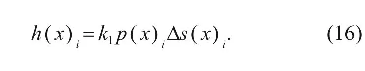
x
is the sum of the wear depth of all incremental steps,and can be expressed as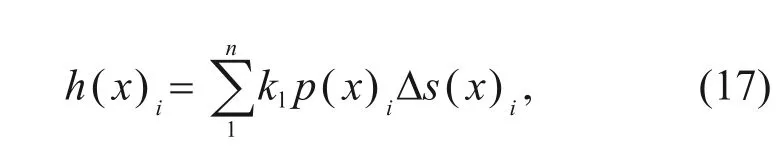
n
represents the total incremental steps.3.3 Numerical calculation method of cyclic loading
3.3.1 Numerical iterative acceleration method
If one step of a finite element simulation calculation only represents the action of one cycle load,the finite element analysis will include thousands of load steps,which will be very time-consuming.In fretting wear,the amount of wear produced by one fretting cycle is very small,and cannot cause significant changes in the contour of the contact surface,so it will not affect the contact stress and other parameters calculated by simulation.Therefore,it is not necessary to update the geometry after each cyclic load in the simulation.It can be assumed that after ΔN
times of cyclic load,the contact surface profile changes significantly.At this time,the geometric morphology of the wear surface needs to be updated,so that the contact stress and relative slip distance after the change of the contact surface profile can be obtained,and provide more accurate data for wear calculation.Therefore,it can be represented by a load step of finite element simulation calculation ΔQ
times of cyclic load,so as to accelerate the calculation and greatly reduce the analysis and calculation time without affecting the calculation accuracy.When the number of accelerations is ΔQ
,the wear depth at positionx
can be expressed as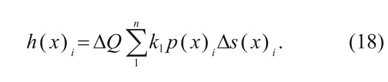
3.3.2 Mesh node updating method
The difficulty of fretting wear simulation is that the contact surface profile changes with the wear process,and leads to a change of contact stress in the contact area,resulting in the real-time change of wear.In this paper,the UMESHMOTION subroutine suitable for finite element mesh generation is written in FORTRAN.The function of the subroutine is to obtain the contact stress and relative slip distance,calculate the wear depth according to the modified Archard equation,and update the nodes of the wear surface of the model after wear.Node updating is realized by adjusting the mesh element of the finite element,which itself will not produce stress and strain.Because of this characteristic,it can be used to simulate fretting wear.The movement of mesh nodes is likely to lead to a huge deformation of the element.In particular,the updated surface of the node may be distorted and unable to continue the calculation,so it also needs the function of automatic mesh adjustment to cooperate,that is,the Arbitrary Lagrangian-Eulerian(ALE) technology in ABAQUS,as shown in Fig.10.This function can make the transition between mesh nodes smooth,so that the mesh can always maintain a more appropriate shape and ensure the convergence of calculation.
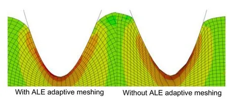
Fig.10 ALE adaptive meshing technology
3.3.3 Numerical model
According to Eq.(8),at the end of each step,the UMESHMOTION subroutine realizes the calculation of damage depth and the update of the grid.Therefore,the flow chart of fretting wear numerical simulation is shown in Fig.11,and the specific steps are as follows:
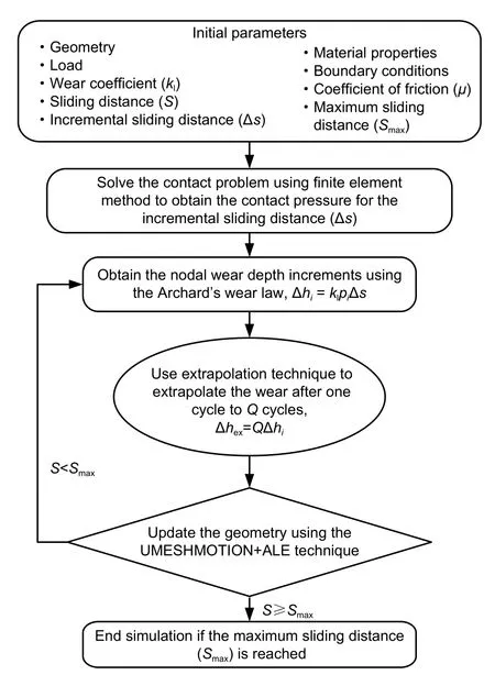
Fig.11 Wear simulation procedure flowchart
1.Determining the initial parameters of the finite element model.
2.Establishing the geometric model in ABAQUS software and generating the INP file.This file contains all the information of the finite element model and can be directly called upon by the solver for analysis.
3.Calling the modified Archard equation for calculation.
4.Solving the INP file in ABAQUS to extract the contact stress and relative sliding distance at each node in the contact area.
5.At the end of each incremental step,the UMESHMOTION subroutine is called upon to calculate the wear depth Δh
and wear volume ΔV
of each node according to the modified Archard wear model.Then,the node is updated according to the wear depth,and the coordinate at nodei
ish
=h
-Δh
.6.After the node is updated,a new surface profile and a new INP file are generated.
7.Counting the number of fretting cycles and judging whether the total number of cycles is reached.If it is not reached,the judgment result is YES,repeating steps 4-7.The fretting wear continues and the wear amount continues to accumulate;if the total number of cycles is judged to have been reached,the judgment result is NO,and the simulation calculation of fretting wear is completed.
3.4 Fretting wear model of the unloading valve
3.4.1 Two-dimensional simplification of computational domain
The aim of this study is the unloading valve in a high-pressure pump,which has circumferential symmetry in structure and the stress conditions on any section are the same.Considering that the original ball structure and more complex valve seat structure are not conducive to grid division and refinement,a 2D spherical/plane contact structure is adopted for simulation.The established simulation structure is shown in Fig.12.The valve seat and valve ball are equivalent to a 2D plane structure.This simplification has the following advantages:(1) Compared with the original structure,it is conducive to refining the mesh of the contact area;(2)Compared with 3D model and slice model,the number of meshes is less,which improves the simulation speed;(3)The boundary conditions suitable for fretting simulation can be added to the model;(4) The 2D grid structure is more conducive to the updating of the grid and can improve the accuracy of calculation.
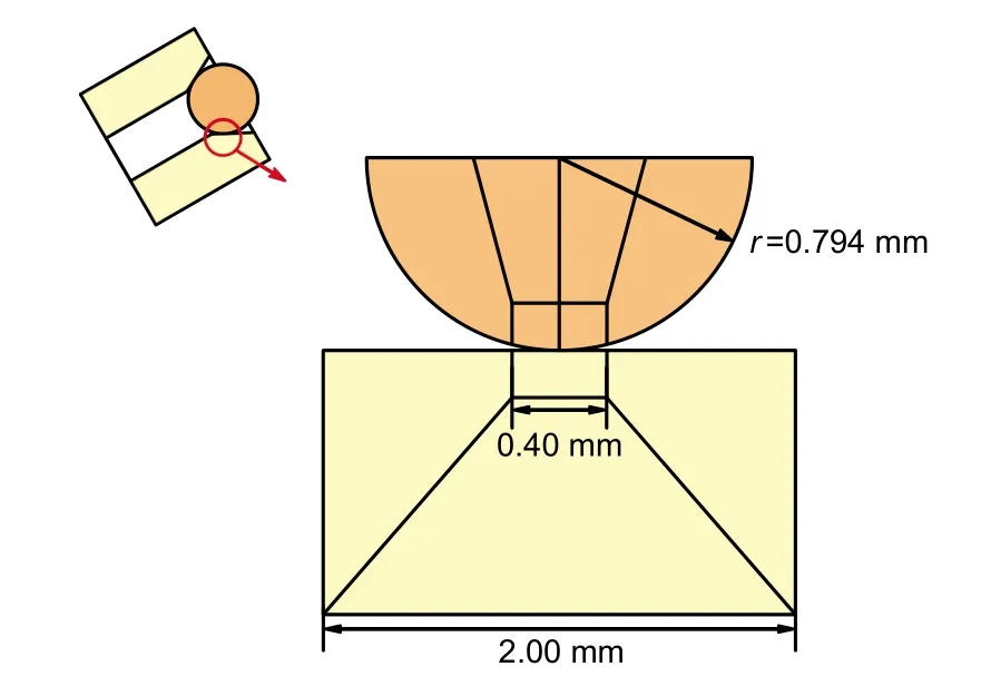
Fig.12 Simplification simulation structure of the unloading valve
3.4.2 Meshing of computational domain
In the simulation structure of this paper,the valve ball and valve seat adopt CPE4 grid of neutral axis algorithm,in which the valve ball contains 1598 elements and 1670 nodes,and the valve seat contains 1520 elements and 1590 nodes.As shown in Fig.13a,in order to prevent the fluctuation of contact pressure,the grid elements in the contact area between the valve ball and the valve seat correspond one to one.To accurately simulate the parameter changes in this area(such as relative slip amplitude,contact stress,and stress distribution on the sub surface),the grid in this area is finely divided (Fig.13b),with a size of about 10 μm.Considering that the non-contact part does not play a key role,this saves calculation time;the grid is sparsely divided,and the size is about 100 μm.
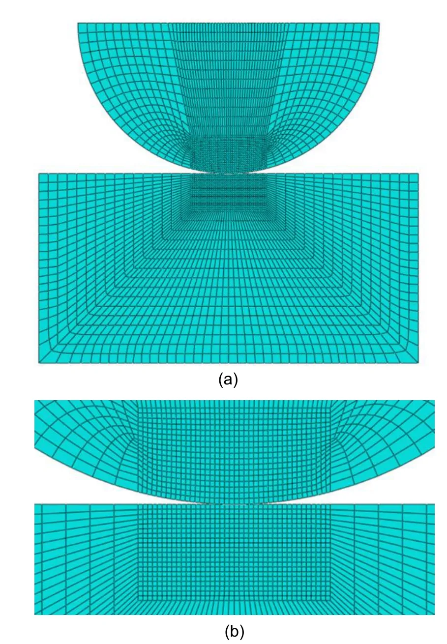
Fig.13 The 2D simulation model of the unloading valve(a);mesh refinement of contact area(b)
Checking the meshing quality,it is found that large or small element angles (minimum angle 45°,maximum angle 135°)appear on a few elements above the valve ball contact area (Fig.14).However,these elements are not the key parts of simulation and the coverage area is also very small,so their impact can be ignored.The average minimum element angle is 75.21°,and the average maximum element angle is 104.78°,then the average aspect ratio is 1.92.There are no elements with too large an aspect ratio and no intersecting elements and zero volume.Generally speaking,the quality of mesh generation is satisfactory and can meet computational requirements.
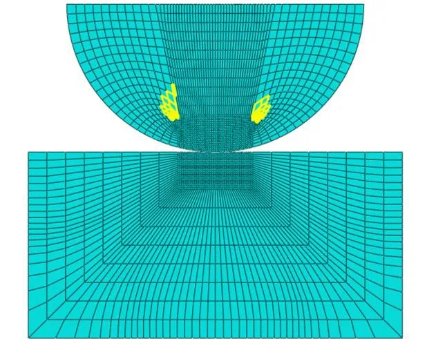
Fig.14 Deviation of the grid angle
3.4.3 Setting of boundary condition
The calculation model of fretting wear of a valve ball is established in ABAQUS,and the material parameters of the model are shown in Table 2.Fixed constraints at the bottom of the valve seat and point edge coupling constraints on the upper surface of the valve ball are added to ensure that the valve ball is always level during loading.A periodic normal loadp
is applied on the upper surface of the valve ball,and a periodic tangential displacement loads
is applied on the centre line,so that the two specimens are in close contact and slide relatively,resulting in fretting wear(Fig.15).Table 2 Material properties
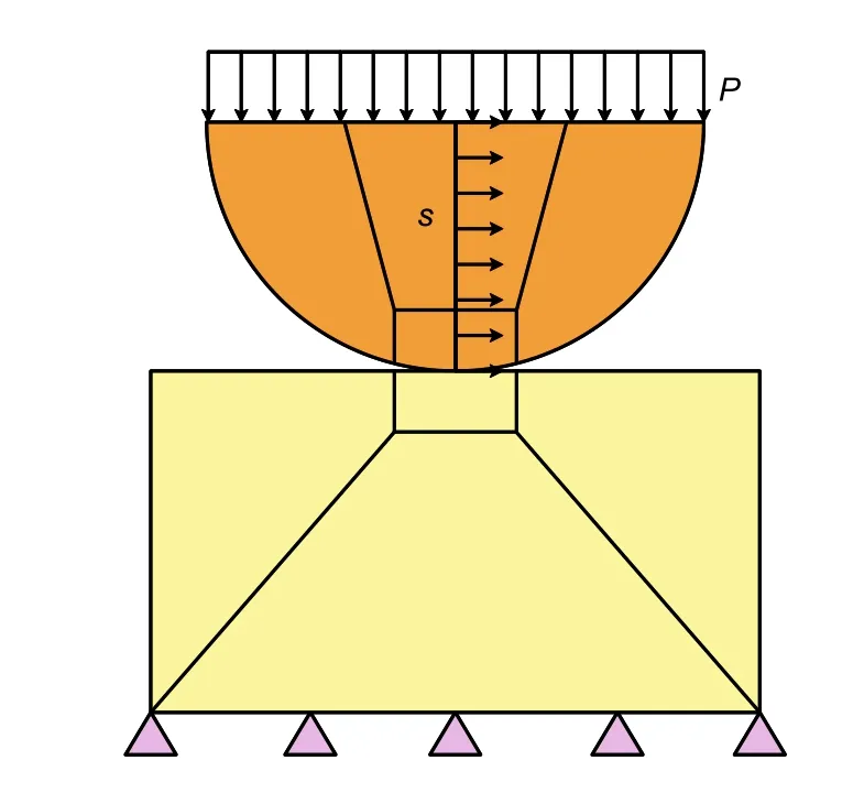
Fig.15 Boundary conditions of the model
Fretting wear occurs in the contact area between the two surfaces of the valve ball and valve seat.The lower surface of the valve ball is set as the main surface,and the upper surface of the valve seat is set as the slave surface.In this way,ABAQUS can quickly and accurately calculate the contact parameters (relative slip distance,contact stress,and shear friction)of the contact area.The tangential behavior is set to the isotropic Coulomb friction law calculated by a penalty function,and the friction coefficient adopts the previously calculated value 0.0887.The normal behavior is set to the hard contact constrained by the standard penalty function.The contact algorithm adopts the finite slip algorithm,and the tangential constraint algorithm is set as in the Lagrange multiplier method.In this way,the relative sliding distance and contact stress obtained will be more accurate.
The two extreme values of valve ball periodic force(5 and 35 MPa)are taken as the boundary conditions of positive pressure and micro slip values,and the positive pressure and micro slip values are added to the simulation load conditions in the form of a periodic alternating cycle.The number of accelerations in the acceleration calculation method ΔN
is set as 1000.Limited by the simulation time,all simulation cases are set as 450 steps.The data of positive pressure and micro-slip distance are shown in Table 3.The two loads are in an alternating state to simulate the respective radial and tangential fretting forms of the valve ball,and thus simulate its fretting wear.Table 3 Loading conditions at different contact angles
3.5 Verification of wear model
The experimental and simulation results of the wear width of the valve ball under different half contact angles with the hardness of the ball and of the seat as HV700 are shown in Fig.16.
Each of the experiments was conducted for 25 h at 500 Hz frequency,so 25×60×60×500=4.5×10cycles were performed for each experimental case.The number of accelerations in the acceleration calculation method ΔN
was set as 10000 and all simulation cases were set as 4500 steps,so 10000×4500=4.5×10cycles were performed for each simulation case.The simulation and experiment have the same cycle times.Therefore,if the simulation results are in good agreement with the experimental results,the accuracy and reasonableness of the simulation have been demonstrated.It can be seen from Fig.16 that both the experiment and simulation show a decreasing trend of wearwidth as the half contact angle increases.Furthermore,errors between the simulation and experimental results under different half contact angles are all less than ±10°.Considering those experimental and measurement errors,it can be assumed that the simulation calculates the fretting wear of the unloading valve well.
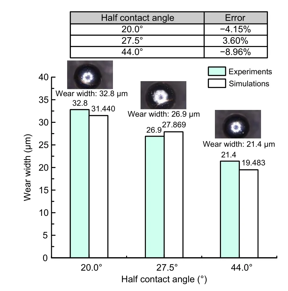
Fig.16 Comparison between experiment results and simulation results of wear width under different half contact angles.Valve ball material:9Cr18Mo;valve seat material:9Cr18MoV;valve ball hardness:HV700;valve seat hardness:HV700
4 Fretting wear characteristics of the unloading valve
4.1 Wear width and depth of different half contact angles
Based on the verified wear model,it is not difficult to find that the wear width of the valve ball decreases as the half contact angle increases.Therefore,it could be speculated that perhaps both the wear width and the wear depth of the valve ball will decrease with the increase in half contact angle.To test this conjecture,simulation cases of five different half contact angles were conducted under the condition of hardness of HV700 for both ball and seat.Because much time is taken if each simulation case is conducted with the same number of cycles as the experimental case the number of accelerations,ΔQ
,was set as 1000 and the number of steps was set as 4500.The number of cycles of the simulation is one tenth of that of the experiment.The simulation results are shown in Figs.17 and 18.It can be seen from Fig.17 that the wear profile of the valve ball is roughly U-shaped.The wear widths on both sides of the highest point of the U-shape are different because the stress states on both sides of the contact point between the valve ball and the valve seat are different,which is consistent with the wear profile of the valve ball in the experimental result.

Fig.17 Wear depth profile variation with different half contact angles (valve ball material:9Cr18Mo;valve seat material:9Cr18MoV;valve ball hardness:HV700;valve seat hardness:HV700) (a);valve ball wear profile (2000-h experiment)(b)
Fig.18 shows the variation of the wear width and depth with different half contact angles.As predicted before,both the wear width and depth decrease with the increase in the half contact angle.This result may be explained by the fact that the wear width is directly proportional to the contact radius between the valve ball and the valve seat,and so the larger the contact area,the larger the wear area.According to Hertz contact theory,the contact radius is directly proportional to the positive pressure and inversely proportional to the contact length.In the process of gradually increasing the contact half angle,the positive pressure between the valve ball and the valve seat increases and the contact length also increases.However,the ratio of the positive pressure and the contact length decreases,so the contact radius decreases with the increase of the contact half angle,and the wear width,which is proportional to the contact radius,also shows the same trend.Therefore,it can be concluded that the wear width and depth of the valve ball will decrease with the increase of the half contact angle of valve ball and valve seat.
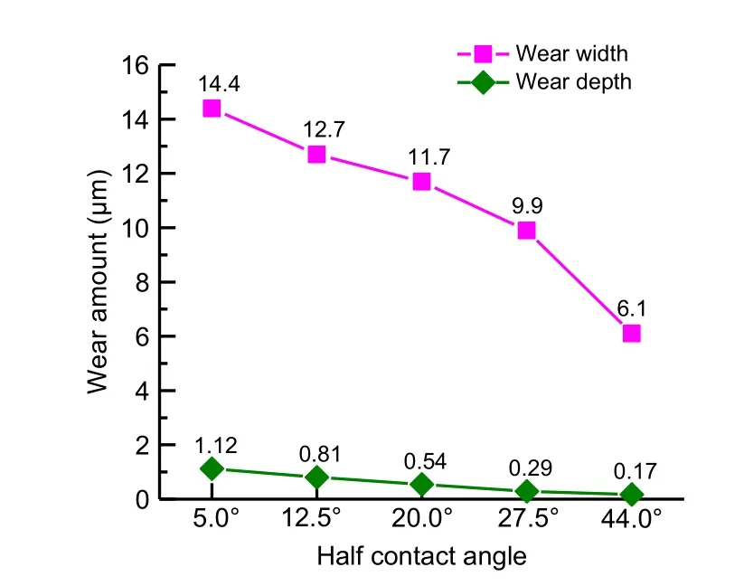
Fig.18 Wear width and depth variation with different half contact angles
4.2 Wear width and depth of different valve ball radii
It can be seen from Table 4 that the increase of valve ball radius will lead to the decrease of positive pressure and micro-slip distance.This leads us to consider how the change of valve ball radius will affect the positive pressure,micro slip distance,and fretting wear of the valve ball.Therefore,according to the same method as in Section 3.1,the radius of the valve ball is changed and the statically indeterminate structure of the ball valve is solved correspondingly,with the half contact angle of valve ball fixed as 27.5° and the hardness of valve ball and valve seat set as HV700.The results are shown in Table 4.The increase of valve ball radius also leads to the increase of positive pressure and the decrease of micro-slip distance.Hence,it cannot directly be inferred from the trend of positive pressure and micro-slip distance that that is how the change of valve ball radius will influence the fretting wear of the valve ball.So simulations are needed to confirm the results.
Table 4 Loading conditions at different contact angles
In the same way as shown in Section 4.1,the number of accelerations ΔQ
was set as 1000 and the number of steps was set as 4500.The simulation results are shown in Fig.19.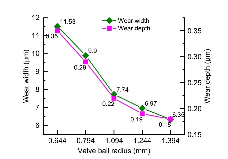
Fig.19 Wear width and depth variation with different valve ball radii
As shown in Fig.19,both the wear width and depth decrease as the valve ball radius increases.Although the positive pressure and micro-slip distance show different variation trends compared to the half contact angle situation,the wear width and depth show the same trend.This may be explained by the fact that the product of positive pressure and microslip distance keeps increasing,although the latter is decreasing.Therefore,it can be concluded that the wear width and depth of the valve ball will decrease with the increase of the valve ball radius.
4.3 Parameter optimization selection
After determining the influence characteristics of radius and half contact angle,it is essential to select the optimal parameters in combination with the actual working conditions of the unloading valve.
Currently the contact half angle of the spherical unloading valve in use is 27.5°.According to the influence characteristics of the contact half angle summarized above,this is not the optimal angle to reduce wear.The diameter of the oil pipe of the valve seat is 1.25 mm and the radius of the valve ball is 0.794 mm.From the engineering perspective,priority should be given to meeting its oil passage area.Therefore,according to its structural parameters,as shown in Fig.20,the maximum possible half contact angle isθ
,which can be calculated by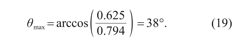
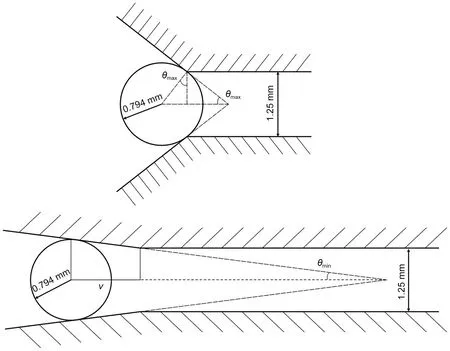
Fig.20 Boundary half contact angle analysis
From the analysis of the fit space between the valve seat and the high-pressure pump body,the minimum half contact angle isθ
when the maximum marginv
is about 5 mm.θ
can be calculated by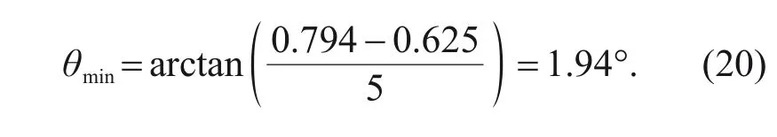
So the range of the half contact angle is 1.94° to 38°.As for the valve ball radius,the value range of 0.704 to 1.963 mm can be calculated in a similar way as the half contact angle.According to the discussion in Sections 4.1 and 4.2,the wear width and depth decrease monotonically with the increase of half contact angle and valve ball radius.Therefore,the maximum values of contact half angle of 38° and ball radius of 1.963 mm can be considered as a better choice for optimizing the unloading valve parameters.
5 Conclusions
Increasingly high pressures in gasoline direct injection technology lead to structural damage in spherical unloading valves.In previous studies,the authors have analyzed the stress characteristics of the unloading valve for addressing this problem and have pointed out that it is caused by fretting wear.Taking that as the premise,this essay describes the design and realization of experiments on fretting wear.Furthermore,theoretical analysis of the statically undetermined structure was made to acquire the boundary conditions of simulations.Based on the modified Archard wear equation,a quantitative calculation model for the unloading valve was established.The following conclusions can be obtained:
1.For 4.5×10cycles fretting wear of the unloading valve,the simulation results are in good agreement with the experiment results.Therefore,the accuracy and rationality of the model can be proved.
2.For 4.5×10cycles fretting wear of the unloading valve under the same hardness of valve ball and valve seat,the simulation results show that the profile of the valve ball is asymmetrically U-shaped.Besides,both the wear width and the wear depth of the valve ball decrease with the increase of the half contact angle.
3.For 4.5×10cycles fretting wear of the unloading valve under identical hardness of valve ball and valve seat,the simulation results show that both the wear width and the wear depth of the valve ball decrease with the increase of the valve ball radius.
Considering the actual application,the half contact angle and valve ball radius have a certain value range.After determining that the value range of the half contact angle is 1.94° to 38° and the value range of valve ball radius is 0.704 to 1.963 mm,according to the law that the wear depth and width decrease with the increase of half contact angle and valve ball radius,suggestions for the optimal selection of unloading valve parameters are made,that is,the valve ball radius should be 1.963 mm and the contact half angle should be 38°.
Acknowledgments
This work is supported by the National Key R&D Program of China (No.2019YFB2001502),the National Natural Science Foundation of China (No.52075387),the Open Foundation of the State Key Laboratory of Fluid Power &Mechatronic Systems (No.GZKF-201907),the Shanghai Municipal Science and Technology Major Project (No.2021SHZDZX0100),and the Shanghai Municipal Commission of Science and Technology Project (No.19511132101),China.
Author contributions
Liang LU and Qi-long XUE designed the research.Man-yi ZHANG,Liang-liang LIU,and Zhong-yu WU provided the experiment equipment and measured data.Yin-peng XU and Liang LU processed the corresponding data.Yin-peng XU wrote the first draft of the manuscript.Meng-ru LI helped to organize the manuscript.Yin-peng XU revised and edited the final version.
Conflict of interest
Liang LU,Yin-peng XU,Meng-ru LI,Qi-long XUE,Man-yi ZHANG,Liang-liang LIU,and Zhong-yu WU declare that they have no conflict of interest.
 Journal of Zhejiang University-Science A(Applied Physics & Engineering)2022年4期
- Journal of Zhejiang University-Science A(Applied Physics & Engineering)的其它文章
- Practice of flow control and smart valves
- Eccentric actuator driven by stacked electrohydrodynamic pumps
- Data-driven fault diagnosis of control valve with missing data based on modeling and deep residual shrinkage network
- Mechanism analysis and evaluation of thermal effects on the operating point drift of servo valves
- Dynamic performance and control accuracy of a novel proportional valve with a switching technology-controlled pilot stage
- Hydraulic directional valve fault diagnosis using a weighted adaptive fusion of multi-dimensional features of a multi-sensor