
Mechanism analysis and evaluation of thermal effects on the operating point drift of servo valves
2022-05-10 10:07:44JianKANGZhaohuiYUANJingchaoLI
Jian KANG,Zhao-hui YUAN,Jing-chao LI
School of Automation,Northwestern Polytechnical University,Xi'an 710072,China
Abstract:Operating point drift over large temperature spans can significantly degrade the performance of servo valves.The direction and magnitude of the deviation of the operating point are uncertain.To analyze and evaluate the mechanism of this complex system with a multi-level structure and multi-variables,it is necessary to construct a theoretical model with a clear physical concept to describe it.However,since the physical processes contain complex variations of structural parameters and flow properties,there is a problem of simplifying approximations in deriving analytical mathematical relations.The advantages of multi-physics field numerical analysis can compensate for this shortcoming of analytical formulations.Based on this,we constructed a whole-valve transfer function model to realize the mechanism analysis and evaluate the operating point drift when a thermal effect acts on a servo valve.The results show that the asymmetric fit relationship between the armature-nozzle assemblies is an important reason for the drift of the operating point caused by the thermal effect.Differences in structural parameters and fluid medium characteristics at different temperatures lead to nonlinear changes in the operating point.When the deviation angle reaches ±1°,an increase in temperature will cause the absolute value of the tangent slope of the displacement deviation of the spool to decrease from 1.44×10⁻⁵ m/℃to 1.25×10⁻⁶ m/℃.The influence of the deviation angle is reflected in the change in the absolute value of the tangent slope of the pressure deviation from 1.14×10³ Pa/℃to 110 Pa/℃.
Key words:Servo valve;Operating point drift;Mathematical model;Numerical analysis;Thermal effect
1 Introduction
Pressure control valves are widely used in aircraft braking systems because of their high precision,high sensitivity,and fast response.However,the large temperature variations during aircraft takeoff and landing pose a significant challenge to the performance of pressure servo valves.Therefore,the mechanism of thermal effects on the operating point drift of pressure servo valves has become a current issue for analysis.
Servo valves are composed of a multi-stage structure,and the thermal effect on the output is the result of the combined effect of several subsystem characteristics.The study of the characteristics of each subsystem forms the basis of the system analysis.The torque motor,as the first stage of the servo valve,was first modeled and analyzed at the theoretical level.To obtain the ideal mathematical model more conveniently,Merritt (1967) considered the magnetic circuit as a 2D plane.Based on this study,an improved torque motor model was derived by considering the reluctance and leakage of permanent magnets(Urata,2000;Zhang QF et al.,2020).Subsequent theoretical modeling attempted to make the model more consistent with the actual physical process by improving the model of the equivalent magnetic circuit (Yan et al.,2017).Equating a 3D problem to a 2D model inevitably ignores some details.Since then,researchers have tried to explain the working process using 3D numerical simulations.The results showed that this method is more accurate than the equivalent model,but the internal pressure characteristics and flow state are still poorly understood.To observe the flow state inside the pilot stage,Mchenya et al.(2011) observed the jet shape,cavitation,and vorticity using a high-speed camera and computer-aided image measurement techniques.However,the experimental method is limited by the precise mating dimensions,which makes it difficult to achieve reproduction of the actual state and accurate data acquisition.To gain insight into the velocity and vortex distribution inside the pilot stage under different flapper positions and inlet pressure conditions,the use of computational fluid dynamics (CFD) techniques is a more suitable approach(Jacob et al.,2011).The results of numerical simulations revealed that cavitation occurs where vortexes are generated (Li et al.,2013).A CFD method was used to try to verify the suppression of this phenomenon by using new flapper and nozzle shapes (Aung and Li,2014;Yang et al.,2019).The high-speed fluid entering the pilot stage impacts the flapper,which is subjected to the main flow force.The vortex that appears after the fluid interferes with the solid flapper makes it subject to a secondary flow force(Aung et al.,2014).To grasp the principles and characteristics of the flow dynamics and the source of forced vibrations of the armature assembly,Li et al.(2018) derived and validated mathematical models of the flow dynamics and forced vibrations.For complex flow states that are difficult to calculate theoretically,numerical simulations can be an effective alternative to experiments (Pan et al.,2011).The numerical simulation technique can effectively compensate for the shortcomings of traditional theoretical analysis and better analyze the system characteristics of actual 3D problems.
For the study of system-level output characteristics,the construction of a mathematical model with clear physical concepts is a more intuitive and desirable approach.Merritt (1968) proposed a third-order mathematical model of a servo valve,which is widely used for its high accuracy.Kim and Tsao (2000) developed a fifth-order system model of a servo valve based on consideration of some nonlinear effects.Based on differential geometry theory,Mu and Li (2011)considered the higher-order nonlinear terms in the system and applied input and output linearization methods to the mathematical modeling of a servo valve.Liu and Jiang(2014)derived a seventh-order model of the dynamic response of an electro-hydraulic servo valve from the nonlinear equations considering two degrees of freedom of the armature-flapper assembly.For high-precision servo valves,it is difficult to accurately represent the dynamic performance of the system by relying only on theoretical modeling methods.Numerical analysis has been used to achieve more accurate predictions of complex flow states in the flow field,which can be used to refine the theoretical models (Pountney et al.,1989).Numerical analysis also enables finite element analysis of critical and precision components,such as feedback rod assemblies and spring tubes,to obtain the required simulation parameters for the actuator system (Somashekhar et al.,2007).Yu et al.(2014) used CFD techniques to evaluate the flow dynamics and valve frequency response characteristics of the new rotary direct drive servovalve spool.Conventional 2D simulations and theoretical calculations always estimate the receiving pressure lower than the experimental data.Yan et al.(2019) proposed two hypotheses about the pilot stage flow distribution based on which a more complete theoretical model can be constructed.It has been demonstrated that the flow field is too complex,and thus an accurate mathematical model cannot be established.Numerical simulations make complex hydrodynamic problems simple,and the results describe the actual physical processes more accurately than do the theoretical models(Li,2016).
The various analytical methods described above are based on performance analysis and characterization of the system in a normal temperature environment.The evaluation of the performance of servo valves in environments with large temperature spans by introducing temperature variables into the system analysis model introduces new problems to be faced.The direct effects of high-and low-temperature environmental conditions on electro-hydraulic servo valves are reflected in structural clearances,fluid characteristics,spool leakage,and material hardness(Zhang et al.,2010).These changes affect the flow coefficient of the throttle orifice and the change of zero control pressure(Zhao et al.,2015).The effect of hydraulic fluid temperature variations on the control characteristics of servo valves can be analyzed based on AMESim software (Chen and Wang,2018).To find out the causes of servo valve current fluctuation due to temperature drift,Li et al.(2017)investigated the servo valve current fluctuation due to temperature drift by simulation.Temperature also affects the spool operating force(Zhang Y et al.,2020).
Therefore,to analyze and evaluate the mechanisms of thermal effects on the operating point of a pressure servo valve,the following work was carried out.Firstly,under the basic assumptions,a fundamental analysis of the forces on the spool was carried out through a problem description,and the various components affecting the spool motion were identified.A theoretical model of the components affecting the spool state was then established based on the working principle of the servo valve,and an expression for the moment containing environmental variables and structural parameters was derived.Expressions with clear physical concepts can explain the mechanism of thermal effects on output.Based on this,the complex physical process was simulated numerically based on a 3D physical model of actual dimensions,taking into account the variation of structural parameters and fluid properties.Finally,a mathematical model of the entire valve was constructed using the mathematical model fitted by numerical analysis.The analysis and evaluation of the mechanism of the thermal effect at the operating point of the pressure servo valve were realized by analyzing the trends of the factors affecting the spool motion.
2 Description of problem
2.1 Composition and working principle of a servo valve
An electro-hydraulic servo valve is usually composed of an electrical-mechanical converter,pilot stage,spring tube,and spool.The double-nozzle flapper pressure servo valve in this study consists of a torque motor,nozzle flapper pilot stage,and spool (Fig.1).The torque motor converts an input electrical signal into mechanical quantities,such as torque and rotation angle,which are then converted by the spring tube into a linear displacement or rotation angle to drive the motion of the pilot stage.
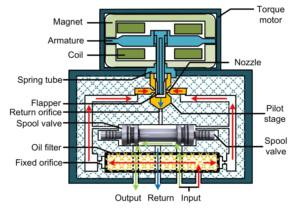
Fig.1 Structure diagram of a nozzle flapper pressure servo valve
The pilot stage of the hydraulic control element has an important influence on the steady-state control accuracy and dynamic response characteristics of a servo valve.The double-nozzle flapper pilot stage uses a frictionless variable throttle orifice amplifier to regulate the control cavity pressure on each side of the spool through the variable throttle orifice overflow area.The spool described here uses integrated pressure feedback to achieve pressure output through the combined effect of differential pressure in the feedback,control cavity,and other forces.
2.2 Basic assumptions
Our purpose was to make the analysis more general and more convenient for subsequent theoretical derivation and numerical analysis.The basic assumptions were as follows:
(1) The shape of the spool and sleeve is ideal cylindrical.
(2) The radial clearance between the spool and sleeve,and the lateral force on the spool,are not considered.
(3) The inhomogeneity of the structure is not considered.
(4)The effect of pressure pulsation generated by the fluid is not considered.
2.3 Analysis of the force balance relationship of the spool and its influencing factors
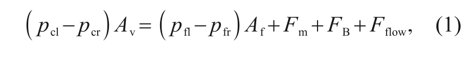
As the last stage of the servo valve,the movement of the spool directly affects the output pressure of the whole valve.The spool is subjected to the control cavity differential pressure force,feedback cavity differential pressure force,flow force,inertia force,and damping force.The differential pressure in the control cavity directly causes the balance of forces on the spool to change and affects the size of the valve opening.
The kinetic equation of the spool can be expressed as
p
andp
are the pressures of the control cavities on the left and right sides,respectively,A
is the area of action of the control pressure,p
andp
are thepressures of the feedback cavities on the left and right sides,respectively,andA
is the area of action of the feedback pressure.F
is the inertia force,F
is the damping force,andF
is the flow force.The force analysis of the valve spool is shown in Fig.2.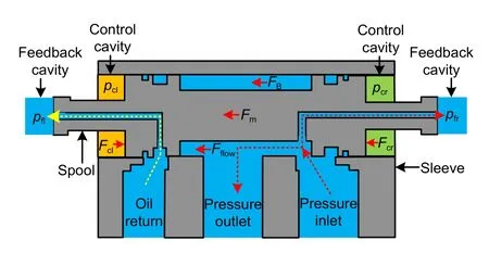
Fig.2 Schematic diagram of the force analysis of valve spool. Fcl and Fcr are the driving forces of the control cavities on the left and right sides,respectively
The drift of the operating point under the action of the thermal effect is due to the destruction of the spool force balance relationship.The factors that affect the control pressure at both ends of the spool include mainly the torque motors,spring tube,and pilot stage components.Therefore,the mechanism analysis and evaluation of the thermal effect on the drift of the servo valve operating point need to be analyzed comprehensively from the system level.
Changes in temperature are most likely to affect the structural parameters of the torque motor and spring tube assembly (Fig.3).The electromagnetic field of the torque motor is used to obtain the electromagnetic torque coefficient,and the structural field of the spring tube assembly is used to obtain the stiffness coefficient.For the subsystems involving the flow field,due to the strong interference between the fluid and the structure,the flow coefficient and the flow force need to be analyzed.
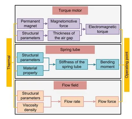
Fig.3 Schematic diagram of the effect of temperature loading on the pressure in the control cavity
In this study,based on the working principle of the servo valve,intensive parameter modeling of each main subsystem was carried out.By constructing a theoretical model with a clear physical concept to describe the relationship between structural parameters,environmental variables,input parameters,and performance,we attempt to explain the mechanism of the thermal effect on the drift of the servo valve operating point.Multiphysics numerical analysis was used to numerically fit the input-output relationship of each main subsystem.On this basis,a full-valve transfer function model was constructed to realize the evaluation of the operating point drift during the thermal effect of the servo valve.
3 Theoretical model of thermal effects acting on the components of the servo valve
The main purpose of this section is to obtain clear mathematical expressions of physical concepts at each stage,based on consideration of the influence of thermal effects on structural parameters and medium characteristics.Analysis of the mechanism of the thermal effect on the drift of the servo valve operating point is based on the physical process.
3.1 Electromagnetic torque of the torque motor
The function of the torque motor is to convert the input control signal into a rotation angle or displacement proportional to the input signal.In this study,we adopted a permanent magnet moving iron type torque motor composed of a permanent magnet,magnetic conductor,energized coil,and armature (Fig.4).The armature is located at the top of the spring tube and can swing around its top in four working air gaps.When the control signal is input,the control magnetic flux generated by the control coil passes through the four air gaps in different directions,so that the sum of the magnetic flux of the air gaps is no longer equal.The force balance of the armature is broken,and the armature generates a torque proportional to the control signal.A schematic diagram and equivalent circuit diagram of the magnetic circuit with intrinsic flux are shown in Fig.5.
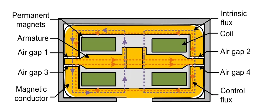
Fig.4 Schematic diagram of the torque motor structure and magnetic circuit
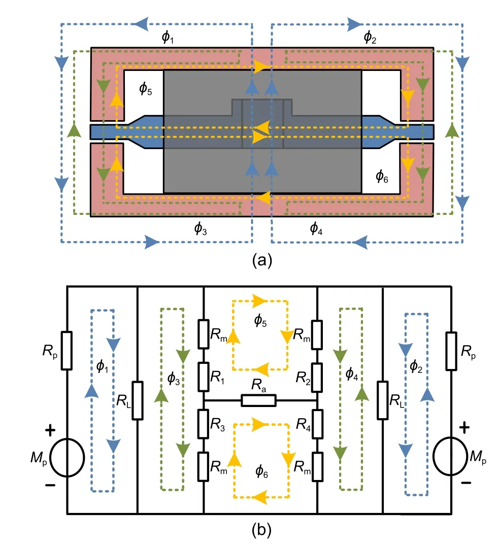
Fig.5 Schematic diagram (a) and equivalent circuit diagram(b)of the magnetic circuit with intrinsic flux(the parameters are explained in the text)
Part of the intrinsic flux generated by the permanent magnet returns to the magnet after passing through the magnetic conductor and the working air gap,while the other part returns to the magnet through the air.The effective fluxes through the magnetic conductor and the working air gap are denoted byφ
andφ
,respectively,while the leakage fluxes are indicated byφ
andφ
.To complete the flux calculation using the mesh current method,let the fluxes inside the armature and conductor circuit beφ
andφ
,respectively.Based on the basic method of circuit calculation,the following expressions for the relationship between magnetic flux,magnetoresistance,and magnetic potential can be obtained:
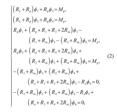
R
(i
=1,2,3,4) is the reluctance of the four working air gaps,R
is the internal resistance of the permanent magnet,R
is the reluctance of the magnetic leakage,R
is the reluctance of the magnet on the magnetic circuit,R
is the reluctance of the armature,andM
is the magnetomotive force of the permanent magnet.Ignoring the reluctance change of the permeable magnet,the air gap reluctance and magnetomotive force will directly affect the magnetic flux of the air gap.We assumed that the flux strength of the magnetic conductor and armature would not saturate,and neglected the hysteresis of the magnetic circuit.
When the temperature rises,the thickness of the air gaps 1 and 2 at the neutral position can be expressed as
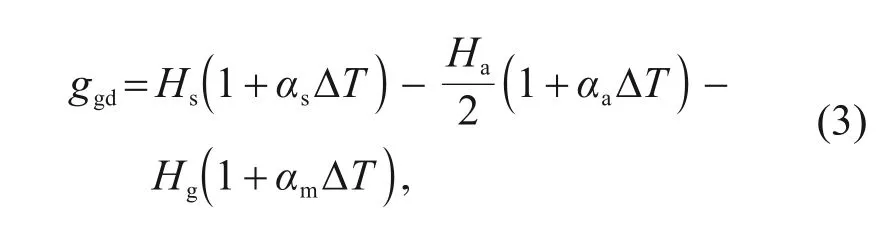
H
is the height of the center of the armature,which is related to the thermal expansion of the spring tube.H
is the thickness of the armature,andH
is the height of the magnetic conductor.α
,α
,andα
are the coefficients of thermal expansion of the spring tube,armature,and magnetic conductor,respectively.T
is the temperature.Similarly,the thickness of air gaps 3 and 4 can be expressed as
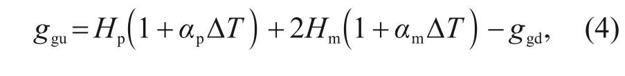
H
is the height of the permanent magnet,H
is the thickness of the magnetic conductor,andα
is the coefficient of thermal expansion of the permanent magnet.The magnetic flux through the air gap is influenced not only by the magnetic resistance,but also by the magnetic potential of the permanent magnets.The magnetic momentum provided by the permanent magnet to the external magnetic circuit after removing the internal reluctance to consume magnetic momentum can be expressed as
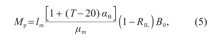
l
is the height of the permanent magnet,α
is the temperature coefficient of remanence,μ
is the magnetic permeability,R
is the irreversible loss rate,andB
is the remanence at room temperature.The relationship between the magnetic field strength and flux density of a permanent magnet is represented by theB
-H
characteristic curve.When theB
-H
curve of the permanent magnet is approximated as linear,the magnetic permeabilityμ
of the permanent magnet can be regarded as a constant.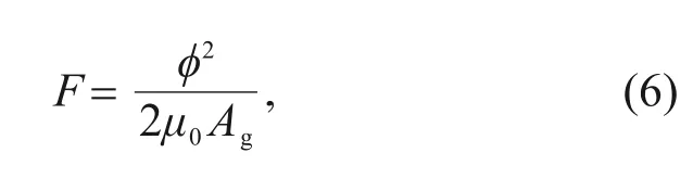
F
is the force acting on the armature’s cantilever,φ
is the magnetic flux passing through the working air gap,μ
is the permeability of air,andA
is the effective area of the air gap.The expression for the electromagnetic moment can be expressed as
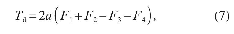
a
is half the length of the armature,andF
(i
=1,2,3,4) are the electromagnetic forces generated by the four working air gaps,respectively.Therefore,the thermal effect will act on the structural parameters of the magnetic conductor and the performance of the permanent magnet.Variations in the properties of permanent magnets affect the intrinsic magnetic flux in the magnetic circuit.At the same time,under the premise of changing the structural parameters of the permeable magnet,the deflection movement of the armature under the action of the control signal will cause a difference in the magnetic flux of the four air gaps.Based on the combined effect of these two main factors,the angle of rotation of the armature and the electromagnetic torque output in different temperature environments will differ from those at room temperature.
3.2 Bending moment of the spring tube
The spring tube is a thin-walled round tubular structure made from a highly elastic beryllium copper alloy with a high elastic modulus.The spring tube is assembled on the valve body between the torque motor and the pilot stage (Fig.6).A flapper located in the center of the armature fits into the spring tube using interference assembly.The armature is activated by the electromagnetic driving force to counteract the torsion moment of the spring tube and the flow force of the pilot stage to deflect the flapper.
The stiffness of the spring tube can be expressed as
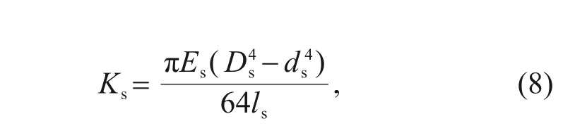
D
andd
are the outer diameter and inner diameter of the spring tube,respectively,l
is the length of the spring tube,andE
is the elastic modulus.Thus,The elastic modulusE
decreases with the increasing temperature,andwhereη
is the temperature coefficient of the modulus of elasticity.Metal physics research shows that the ratio of the temperature coefficient of elastic modulusη
to the linear expansion coefficientα
is a constant value of 0.04.The expression for the change in stiffness with respect to the change in temperature can be written as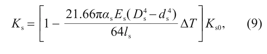
K
is the stiffness of the spring tube at room temperature.Therefore,the thermal effect will act on the elastic modulus and structural parameters of the spring tube,thereby affecting its stiffness.Under different thermal loads,the same action will result in different bending moments and deflection angles.
3.3 Hydrodynamic torque of fluid
The thermal effect on the pilot stage and the valve body is directly manifested in the thermal expansion and fluid characteristics of the structure.Previous studies have found that the influence of temperature on fluids is reflected mainly in two properties:viscosity and density.The viscosity and density characteristics of fluids can be modeled by the following equations:
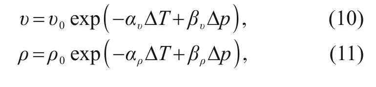
υ
andρ
are the kinematic viscosity and fluid density at normal temperature,respectively.α
andα
are the temperature coefficients,andβ
andβ
are the pressure coefficients.p
is the pressure of the oil.Temperature has a more significant effect on fluid properties than does pressure.Therefore,we considered only temperature in this study and ignored the influence of pressure.The flow coefficient of the throttle orifice is related to the Reynolds number.The Reynolds number characterizes the ratio of the inertial and viscous forces of a fluid,which determines whether the flow pattern of the fluid is laminar or turbulent.The Reynolds number of a fixed throttle orifice can be expressed as
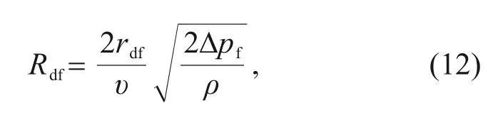
υ
is the viscosity,r
is the radius of the fixed throttle orifice,and Δp
is the pressure difference between the two sides of the orifice.The Reynolds number of the nozzle can be expressed as
D
is the nozzle diameter,x
is the initial distance between the nozzle and the flapper,x
is the displacement of flapper,and Δp
is the pressure difference across the nozzle.Thermal effects will directly affect the Reynolds number through density,viscosity,and structural parameters.Based on previous studies,we conclude that the flow coefficient is a function of the Reynolds number.
The nozzle ejects fluid that acts on the flapper flow force in two main ways.On the one hand,flow force is generated by the stagnation pressure in the nozzle projection area.This is due to the high-speed impact of the fluid on the flapper surface,converting the kinetic energy of the fluid into static pressure energy.On the other hand,flow force is generated by the change in fluid momentum on the remaining flapper surface outside the nozzle projection area.
F
andF
are the flow forces on each side of the flapper,p
andp
are the pressures of the control cavity on each side of the spool,respectively,C
is the flow coefficient of the nozzle,andp
is the return pressure.Therefore,the thermal effect will cause changes in fluid properties and structural parameters,which will directly affect the flow force.The force balance relationship of the spool and the working point of the whole valve is determined mainly by the flapper-nozzle gap flow resistance.The position of the flapper depends on the combined effects of the electromagnetic moment,the bending moment of the spring tube,and the hydrodynamic moment.These critical moments to which the armature-flapper assembly is subjected are all functions of temperature.Therefore,such complex system problems need to be evaluated with the help of mathematical models of the whole valve to assess their performance.However,there is the problem of simplifying the approximation in deriving the analytical mathematical relationships,and a multi-physics field numerical analysis is needed to analyze the forces on the armature-flapper assembly.
4 Simulation results and discussion
Within complex systems containing electromagnetic,fluid,and solid interactions,it is difficult to study the thermal effects of servo valves by theoretical analysis alone,especially the interference between fluids and solids present in the pilot stage and valve body.To obtain a more accurate model of the local characteristics of each stage and to further evaluate the effect of thermal effects on the operating point drift of the servo valve,numerical simulations of the electromagnetic field of the torque motor,the structural field of the spring tube,and the flow field of the pilot stage are described in this section.
4.1 Numerical simulation of electromagnetic torque on the armature
In the theoretical analysis section,the output torque equation was derived by analyzing the magnetic circuit of a simplified 2D torque motor.Due to the non-axisymmetric structure of the torque motor and the complexity of the magnetic circuit,if the structure is considered as a 2D problem then many details related to the structure are ignored.In addition,there are approximate estimates for the calculation of the air gap reluctance,component reluctance,and leakage flux,which eventually lead to some deviations in the coefficients in the electromagnetic torque equations.
To understand the change law of electromagnetic torque and the influence of thermal effects more clearly,numerical simulations of electromagnetic torque under different angles and temperatures were carried out.The model of the torque motor is shown in Fig.6.The permanent magnet material is LNGT60,which is characterized by a relatively small temperature coefficient and a small change in magnetic properties caused by temperature changes.At 40 ℃,the permanent magnet has a remanence of 0.9 T,a coercivity of-11 kA/m,and a relative permeability of 6.51.Both the magnet conductor and armature are made of iron-nickel soft magnetic alloy 1J50,which has relatively high permeability and low coercive force in low magnetic field environments.The structure of this alloy does not change significantly under the effect of temperature.There are 1100 turns of wire loops on each arm of the armature.
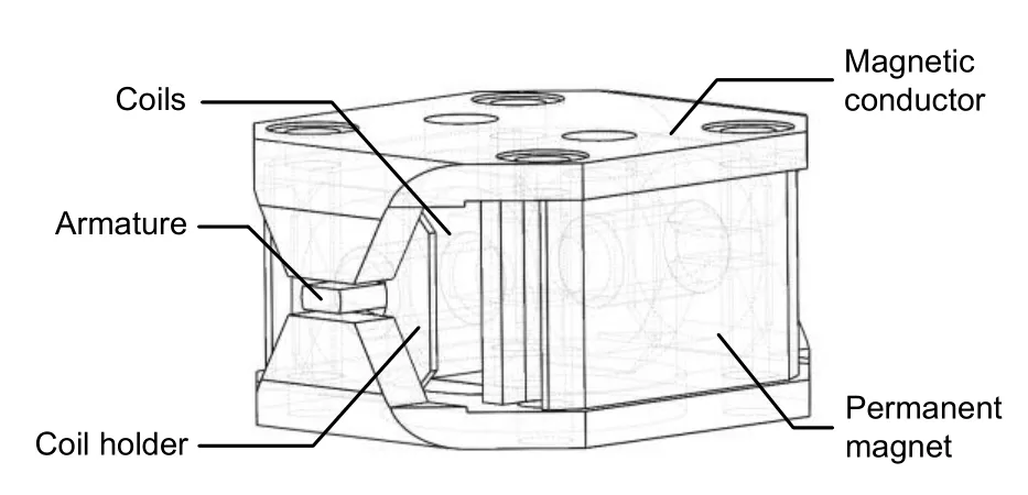
Fig.6 Three-dimensional model of the torque motor used for numerical analysis
As shown in Fig.7,the electromagnetic torque grows in an essentially linear manner during the deflection of the armature within the limits.At the same deflection angle,the electromagnetic torque decreases with increasing temperature.In the case of an armature deflection angle of 0.1°,the electromagnetic torque is 0.019835 N·m when the temperature is 40 ℃,decreasing to 0.018974 N·m when the temperature increases to 120 ℃.The amount of change in torque will be even smaller when the armature is within a deflection angle of 0.1°.According to the theoretical analysis,the armature deflection angle and the electromagnetic torque are linearly related,and the coefficient can be defined as the electromagnetic spring torque coefficientK
.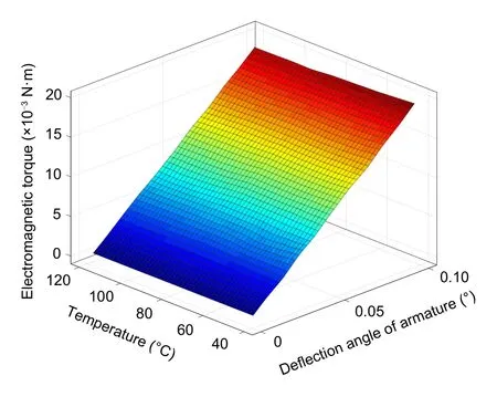
Fig.7 Simulation results of electromagnetic torque
The expression for the electromagnetic moment derived from the theoretical analysis can be expressed as
K
=-0.004837 N·m/(rad·℃) is the temperature coefficient of the electromagnetic moment,and coefficientK
=11.61 N·m/rad.Accordingly,thermal effects can influence the electromagnetic torque by changing the structural parameters and the permanent magnet characteristics.The structural parameters directly affect the reluctance of the magnet conductor and the operating air gap,while the permanent magnet characteristics determine the magneto dynamic potential.
4.2 Numerical simulation of the flow coefficient of the orifice
The nozzle flapper servo valve relies mainly on a multi-stage throttling structure to achieve control of the output.In particular,the variable throttle orifice of the pilot stage realizes the adjustment of flow resistance by changing between the flapper and the nozzle.Analysis of the flow characteristics of the throttle structure is necessary.The first factor that should be considered for the numerical analysis of the flow field is the fluid properties.A nonlinear least-square method based on the trust-region algorithm is used to fit the available oil property data,and temperature coefficients of fluid viscosity and density are 0.0626 and 0.000575,respectively.
For the analysis of the influence of the thermal effects of the flow field in the valve,it is necessary to consider not only the characteristics of the fluid,but also the variation of the key structural dimensions.Among the structural parameters are the diameter of the fixed throttle orifice,the diameter and length of the nozzle,and the width of the flapper.The variation patterns of these structural parameters are based on the equations in the theoretical calculation section.The 3D model created is shown in Fig.8,in which as many structural details as possible are preserved.
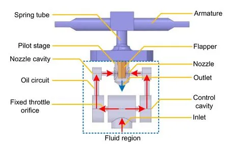
Fig.8 Three-dimensional model of the fluid domain inside the valve
Considering the symmetry of the structure,the calculation domain adopts a single nozzle structure.This can effectively reduce the computational burden caused by the excessive number of grids,and can collect data more conveniently.Considering irregular geometric shapes and large-scale changes,polyhedra elements are more suitable for meshing.By using the fixed type size function,a finer grid is constructed around the flapper-nozzle gap area and the fixed orifice.The results of grid independence analysis show that the adopted grid can obtain reasonable and acceptable results.The number of element grids was 1972034,and the skewness values were all less than 0.7(Fig.9).
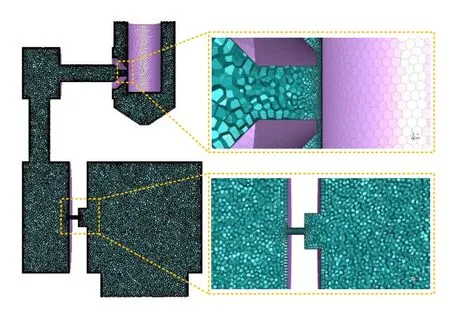
Fig.9 Meshing of the computational domain
The corresponding boundary conditions were set according to the actual working conditions of the servo valve.There are three types of boundaries set in the calculation domain,namely the pressure inlet,wall boundary,and pressure outlet.Wall type boundaries confining the fluid or solid regions are defined at all other surfaces.For viscous flow,the no-slip stationary condition is applied by default.Simulated by FLUENT,the flow medium is aviation hydraulic oil,and the inlet pressure is set as 21 MPa during the calculation,while the outlet pressure is kept constant at 0.4 MPa.For turbulent behaviors,the set of turbulent kinetic energy and dissipation rate equations are solved using the standardk-ε
model.In the pressure-velocity coupling,the SIMPLEC scheme is used since it allows the higher pressure-correction under relaxation factor that helps to speed up convergence.In spatial discretization,the body“PRESTO!”scheme is used for pressure discretization to work flexibly in a complex computational domain.The first-order upwind is applied for the momentum and the set of standardk-ε
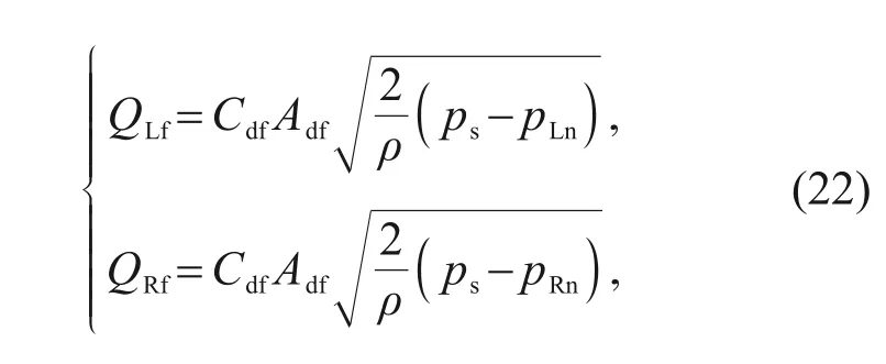
equations.Since the structure of the flow channel in the valve body is symmetrical,only half of each structure is used as the calculation domain to facilitate data collection,while also saving energy,computer memory,and calculation time.The inlet pressure and outlet pressure are set boundary conditions.The pressure loss between the control cavity pressure and the nozzle cavity can be ignored,and the control cavity pressure can be easily collected.Based on the flow continuity,the flow rate of the inlet is equal to that of the nozzle and fixed orifice,and its value can be obtained.According to Eqs.(22)and(23),the flow coefficients of the fixed orifice and the nozzle can be easily obtained.According to the flow equation at the throttle orifice,the curved surface of the flow coefficient of the fixed orifice and the nozzle under the combined action of different pressure differences and thermal effects can be obtained,as shown in Fig.10.
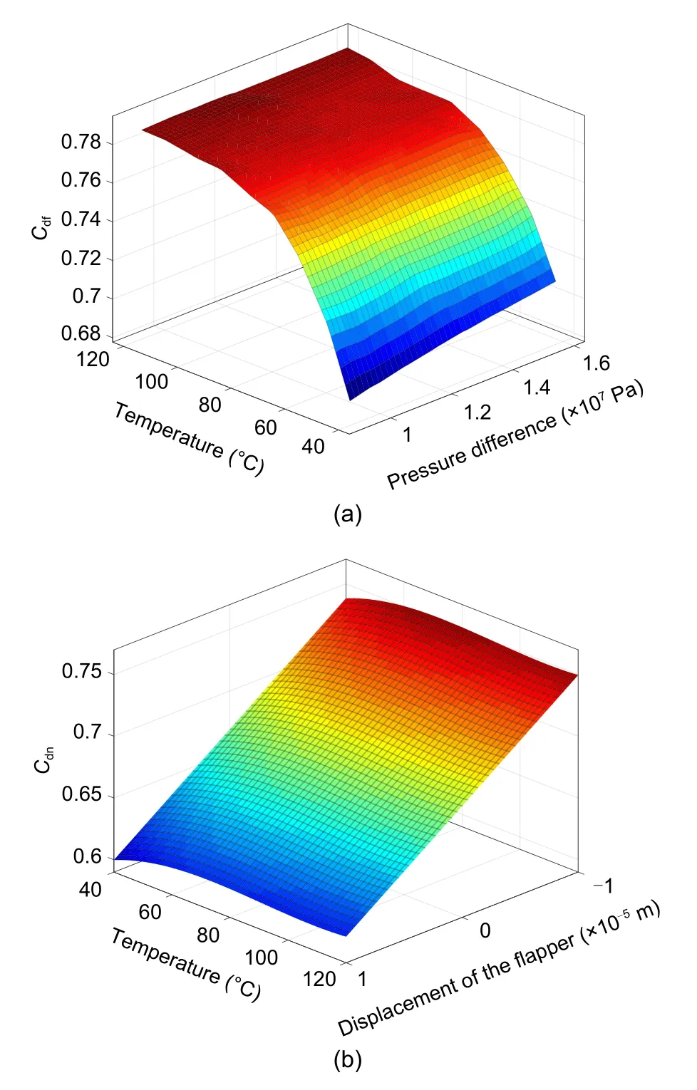
Fig.10 Curved surface of the flow coefficient of the fixed orifice and the nozzle under the combined action of different pressure differences and thermal effects:(a) flow coefficient of the fixed throttle orifice (Cdf);(b) flow coefficient of the nozzle(Cdn)
Based on the numerical analysis,expressions for the flow coefficients of fixed throttle orifices under the influence of thermal effects can be obtained:
c
=4.196×10,c
=-1.226×10,c
=1.202×10,andc
=0.3875.With the change of the flapper displacement,the nozzle flow shows basically a linear trend.However,when the flapper is at the same offset,the thermal effects make the flow show nonlinear behavior.From the maximum flow rate at 80 ℃,temperature increases or decreases will reduce the flow rate through the nozzle.Based on the fitted curve,an expression for the nozzle flow coefficient under the influence of thermal effects can be obtained:

k
=-2.26×10,k
=-5.11,k
=1.47×10,k
=-4×10,k
=3.49×10,andk
=0.5841.Therefore,the influence of environmental variables and structural parameters on flow characteristics can be obtained through numerical simulation.Thermal effects can affect the fluid flow state by changing fluid characteristics and structural parameters.The effect can be evaluated by numerical simulation of explicit expressions with physical concepts.
4.3 Numerical simulation of the flow force on the flapper
After the high-speed fluid in the nozzle enters the pilot stage volume cavity,the impact force on the flapper surface is the flow force.The components of the flow force are complex,and the theoretical analysis can be divided roughly into the static pressure on the nozzle projection area and the flow force generated by the vortex.
The length of the pipeline is appropriately shortened without affecting the flow field solution.According to the results of the theoretical analysis,the stagnation pressure is generated by the flow force,nozzle diameter,and the pressure of the nozzle cavity,while the fluid momentum generated by the flow force is also related to the flow coefficient and the flapper-nozzle gap width.The nozzle flapper structure under the influence of thermal effects,and the deflection of the flapper have been parameterized in Solidworks.To obtain a clearer overview of the pressure distribution on the flapper surface,the pressure distribution on each side of the surface of the flapper was collected at different offset positions of the flapper(Fig.11).
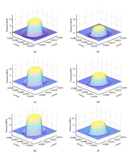
Fig.11 Pressure distribution on each side of the surface of the flapper at different temperatures when the displacement of the flapper xf=10 μm:(a)T=40 ℃,left surface;(b)T=40 ℃,right surface;(c)T=80 ℃,left surface;(d)T=80 ℃,right surface;(e)T=120 ℃,left surface;(f)T=120 ℃,right surface
There is a distinct circular peak in the central region of the nozzle and a circular low-pressure area around the peak.When the flapper moves to the left,the pressure in the left nozzle chamber is higher and the flow rate at the outlet increases.Therefore,the surface stagnation pressure is also greater when the kinetic energy of the nozzle jet fluid increases.As the flapper offset increases,the peak on the left gradually increases and the peak on the right gradually decreases.Between the peak and the annular low pressure area is a pressure gradient area,in which the pressure drops smoothly and rapidly.The periphery of the annular low-pressure zone,that is,the remaining area of the flapper,can be called a flat area.The pressure in the flat area is slightly higher than the return pressure.
The areas of the peak,ring,and flat regions remain essentially constant at different temperatures.However,the amplitudes of the peak and flat region gradually increase with rising temperature.In contrast,the pressure in the annular low pressure region reduces with increasing temperature.
The numerical simulation results of the flow force for different displacements of the flapper and different temperatures are shown in Fig.12.At the same temperature,the variation of the flow force appears essentially linear.However,at the same offset,the effect of temperature on the flow dynamics is relatively large.In particular,at an offset of 10 μm,the flow force decreases rapidly from 0.575 to 0.152 N when changing the temperature from 40 to 60 ℃.The flow force is the lowest at 60 ℃and then shows a nonlinear increase with the gradient of the gradual decrease in growth.The exponential change between fluid viscosity and temperature characteristics greatly affects the fluid motion characteristics.This effect is more obvious when the gap between the nozzle and the flapper is large.
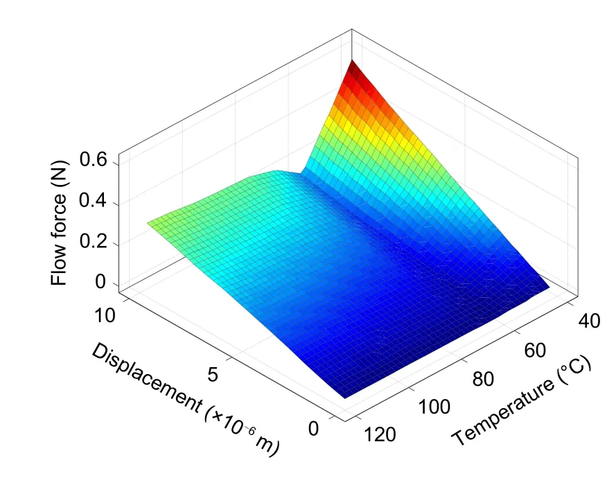
Fig.12 Numerical simulation results of the flow force at different displacements of the flapper and different temperatures
Therefore,the expression for the relationship between the flow force and temperature can be written as
c
=1.1×10,c
=-4.09,c
=
547,c
=-3.158×10,andc
=6.823×10.The numerical analysis shows that the effect of temperature and flapper offset on the flow state of the fluid is significant.
5 Analysis and evaluation
In the previous sections,the numerical simulation results of complex links have realized the numerical fitting and parameter correction of the theoretical model.The purpose of this section is to synthesize the results of the above analyses and analyze the influence of thermal effects on the output of the servo valve by modeling the transfer function of the entire valve.A modular block diagram of the whole valve performance analysis is shown in Fig.13,which is divided into three main parts:the torque motor,pilot stage,and spool.The nomenclature of the simulation parameters of the servo valve is shown in Table 1.
Table 1 Nomenclature table of simulation parameters
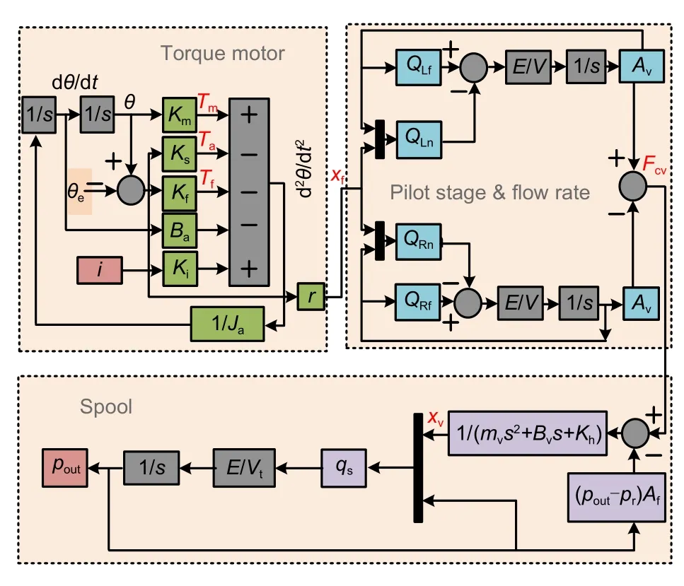
Fig.13 A modular block diagram of the whole valve performance analysis
The equilibrium equation for the torque on the armature-flapper assembly can be obtained by applying Newton’s second law and rigid body dynamics:
K
is the coefficient of neutral electromagnetic torque,andF
is the flow force on the flapper.Since the angle of rotation is relatively small,the relationship between the angle of rotation of the armature and the displacement can be approximated as

The nozzle flapper pilot stage consists of the flapper,fixed orifice,nozzle,and oil return orifice.The nozzle and the movable flapper create two-variable gaps,forming two structures similar to variable orifices(Fig.14).According to the throttling equation,the flow rate through the fixed throttle orifice can be expressed as
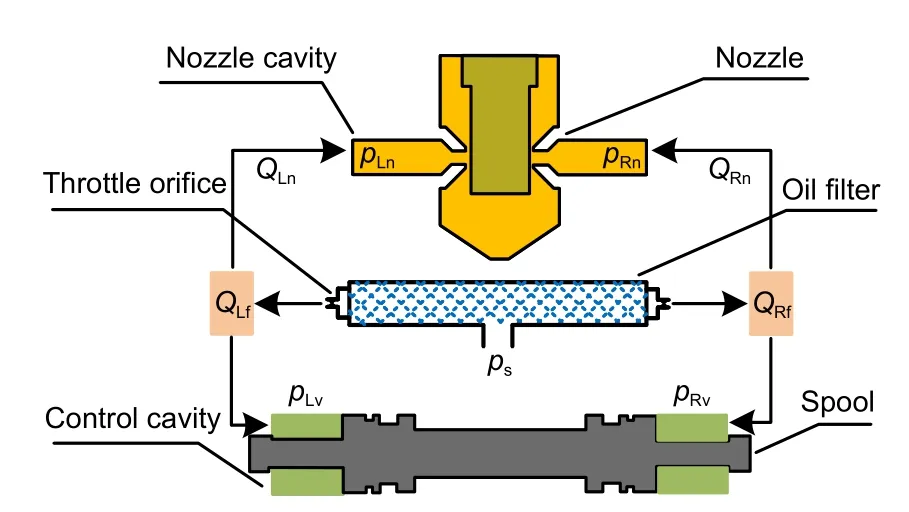
Fig.14 Schematic diagram of the structure and flow distribution of the valve body.pLv and pRv are the pressures in the control cavities on the left and right sides of the spool,respectively
A
is the area of the throttle orifice.Assuming that the flapper is offset from the neutral position byx
distance,the flow rate from each side of the nozzle can be expressed as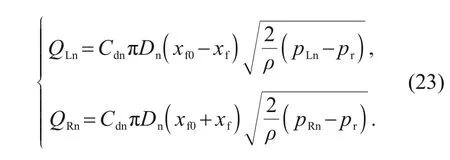
Since the volume of the cavity has little effect on the pressure of the control cavity,the effect of temperature on the volume of the cavity is ignored.Considering the compressibility of the closed cavity at both ends of the valve spool,the pressure in the control cavity can be expressed as
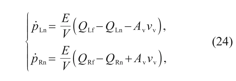
v
is the speed of the spool movement.Therefore,the control driving force of the valve spool can be expressed as
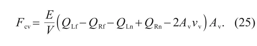
The change of control force will affect the force balance state of the spool,which is also the factor with the most direct influence on the operating point drift of the servo valve under the thermal effect.
Since the spool used in this study has an integrated feedback structure,a dynamic equilibrium equation of the spool can be established:
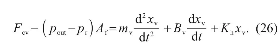
Considering the oil compressibility,the relationship between the output flow rate and the displacement of flow rate of the servo valve output can be expressed as
C
is the flow coefficient of the orifice of the spool,W
is the area gradient,andx
is the overlap of the slide valve.When there is no input control current signal,the static equilibrium equation of the armature-flapper assembly can be written as
K
is the flow force stiffness coefficient obtained by numerical analysis.Assuming that the armatureflapper assembly maintains a vertical matching relationship,whether it is in the neutral position or the overall deflection,its position will be stable at the neutral position.We assumed that the armature,spring tube,and nozzle flapper had a deviation angle during processing or assembly.The deviation angle of these elements can be converted into an additional deflection angle of the armature.Therefore,the above formula can be written as
When the pressure difference of the control cavity is enough to drive the spool to produce output pressure,the spool will close again under the action of the feedback force.To facilitate the analysis of the spool movement range,it can be assumed that the spool has a large overlap.When there is no input signal,the analysis of the displacement of the spool is realized by setting different deviation angles and temperatures.
In the two cases of positive and negative deviation angles,the effect of temperature on the spool displacement is completely different.Thez
-axis in Fig.15 is the relative value of the steady-state position of the spool at the zero deviation angle.The direction of the deviation angle is the same as the movement direction of the spool.The greater the absolute value of the deviation angle,the greater the deviation of the spool deviation.This means that when the deviation angle of the armature assembly is positive,the dead zone of the servo valve will gradually increase as the temperature increases.Conversely,when the deviation angle is negative,the increase in temperature will cause the dead zone of the servo valve to decrease.When the deviation angle reaches 1°,in the range of 40-50 ℃,the displacement deviation decreases from 5.68×10m to 4.24×10m,and the tangent slope of the displacement deviation reaches 1.44×10m/℃.In the range of 110-120 ℃,the displacement deviation is reduced from 1.60×10m to 1.48×10m,and the tangent slope of the displacement deviation is only 1.25×10m/℃.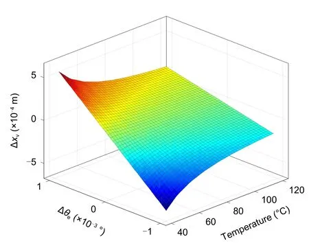
Fig.15 Variation in the displacement deviation of the spool with the temperature and deviation angle
When the torque motor has a 20-mA input signal,the deviation of the output pressure varies with the temperature and deviation angle as shown in Fig.16.Thez
-axis is the relative value of the output pressure at the zero deflection angle,which can be defined as the deviation pressure.A larger deviation angle will result in a greater deviation pressure.The deviation pressure is more obvious at lower temperatures.When the deviation angle is positive,the output pressure drop gradually decreases as the temperature increases.The reduction process is nonlinear,and the gradient is relatively large in the relatively low temperature stage.When the deviation angle is negative,the temperature increase will cause the output pressure to increase.This indicates that the variation of the operating point caused by the deviation angle in the positive and negative directions under the action of the thermal effect is opposite.When the deviation angle reaches 1°,in the range of 40-50 ℃,the pressure deviation decreases from 4.49×10Pa to 3.35×10Pa,and the tangent slope of the pressure deviation reaches 1.14×10Pa/℃.In the range of 110-120 ℃,the pressure deviation is reduced from 1.27×10Pa to 1.16×10Pa,and the tangent slope of the pressure deviation is only 110 Pa/℃.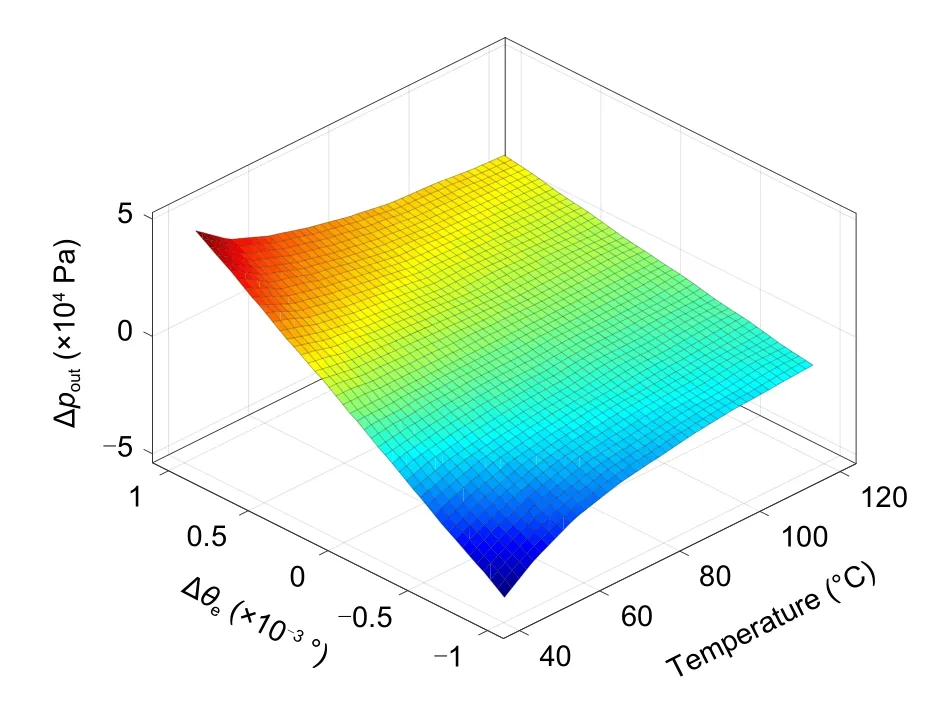
Fig.16 Variation in the deviation of the output pressure with the temperature and deviation angle
6 Conclusions
Based on the physical process of the servo valve,we first established a mathematical model of the key links under the action of the thermal effect to illustrate the mechanism of the thermal effect acting on the operating point of the servo valve.To evaluate the thermal effect,a mathematical model of the entire valve was established based on the results of numerical simulation.Based on the above analysis results,the main conclusions were as follows:
(1)The thermal effect will affect the electromagnetic torque of the torque motor and the bending torque of the spring tube by changing the structural parameters.In addition,the matching relationship of the structure and the difference in the characteristics of the fluid will affect the flow force acting on the flapper.
(2) Through the numerical simulation of each stage,the expression of the fitting relationship between input,output,and temperature was obtained.The influence of temperature on the electromagnetic torque output by the torque motor is about 5%,and its changing trend with temperature is relatively linear.The change trend of the discharge coefficient is more complicated,and the influence of temperature on the discharge coefficient of the nozzle is about 2%at most.Temperature will not only change the fluid characteristics,but also have a significant impact on the pressure difference and structural coordination.In addition,the difference of the above factors will also affect the flow force,which will be reduced to about 60%of the normal temperature.
(3)According to the working principle of the servo valve,a mathematical model of the whole valve was established.On this basis,the influence of the thermal effect on the drift of the operating point was evaluated.When the deviation angle reaches±1°,within the range of 40-50 ℃,the tangent slope of the displacement deviation reaches 1.44×10m/℃,and the tangent slope of the pressure deviation within this range can reach 1.14×10Pa/℃.An increase in temperature will gradually reduce the slope of the tangent.In the range of 110-120 ℃,the above values will be reduced to 1.25×10m/℃and 110 Pa/℃,respectively.Therefore,we conclude that the deviation angle of the armatureflapper is an important factor affecting the drift of the operating point.
In conclusion,the mechanism of the working point drift of servo valves under thermal effects is related to the structural and fluid characteristics.The deviation angle between components generated during the process of machining or assembly will directly lead to the working point drift.Moreover,the direction of the deviation angle will affect the drift direction of the operating point and the output amplitude.
Acknowledgments
This work is supported by the Civil Aircraft Research Project(No.MJ-2016-S-54),China.
Author contributions
Jian KANG designed the research and wrote the first draft of the manuscript.Jing-chao LI processed the corresponding data and helped to organize the manuscript.Zhao-hui YUAN revised and edited the final version.
Conflict of interest
Jian KANG,Zhao-hui YUAN,and Jing-chao LI declare that they have no conflict of interest.
 Journal of Zhejiang University-Science A(Applied Physics & Engineering)2022年4期
- Journal of Zhejiang University-Science A(Applied Physics & Engineering)的其它文章
- Practice of flow control and smart valves
- Eccentric actuator driven by stacked electrohydrodynamic pumps
- Analysis of fretting wear behavior of unloading valve of gasoline direct injection high-pressure pump
- Data-driven fault diagnosis of control valve with missing data based on modeling and deep residual shrinkage network
- Dynamic performance and control accuracy of a novel proportional valve with a switching technology-controlled pilot stage
- Hydraulic directional valve fault diagnosis using a weighted adaptive fusion of multi-dimensional features of a multi-sensor