
Blast response of clay brick masonry unit walls unreinforced and reinforced with polyurea elastomer
2022-04-19 04:02:56GngWuChongJiXinWngFuyinGoChngxioZhoYujunLiuGuiliYng
Defence Technology 2022年4期
Gng Wu , Chong Ji , Xin Wng ,*, Fu-yin Go , Chng-xio Zho , Yu-jun Liu ,Gui-li Yng
aCollege ofFieldEngineering,ArmyEngineering Universityof PLA,Nanjing, 210007, China
bArmy Infantry Academy ofPLA,Nanchang, 330103,China
cShanxi Polyurea ProtectiveMaterialsCo.Ltd, Taiyuan, 030006,China
Keywords:Clay brick masonry unit wall Polyurea Blast loading Failure grade Reinforcement mechanism
ABSTRACT Clay brick masonry unit (CBMU) walls are widely used in building structures, and its damage and protection under explosion loads have been a matter of concern in the field of engineering protection.In this paper, a series of full-scale experiments of the response characteristics of 24 cm CMBU walls unreinforced and reinforced with polyurea elastomer subjected to blast loading were carried out. Through setting 5.0 kg TNT charges at different stand-off distances,the damage characteristics of masonry walls at different scaled distances were obtained. The reinforcement effect of different polyurea coating thicknesses and methods on the blast resistance performance of masonry walls under single and repeated loads were also explored. Five failure grades were summarized according to the dynamic response features of masonry walls. Based on the stress wave propagation pattern in multi-media composite structures, the internal stress distribution of masonry walls were analyzed,and the division basis of the masonry walls’ failure grades was then quantified. Combined with Scanning Electron Microscope(SEM)images, the deformation characteristics of soft and hard segments of polyurea and effects of detonation products on microstructures were revealed respectively, which provides an important reference for the design and application of polyurea in the blast resistance of clay brick masonry walls.
1. Introduction
As the most common component form, masonry unit walls are widely used in building facade enclosure or non-structural division of internal space. However, due to the lack of out-of-plane load resistance,the infilled wall is prone to damage and collapse under explosion loads, resulting in mass casualties and property losses.Even if the whole building structure is not collapsed, a large number of debris will be produced,causing casualties and damage to the internal facilities of the building.
The protection design of masonry unit walls has always been a hot issue.There are many ways to reinforce the masonry walls.One is to enhance the overall strength of concrete matrix, such as adding reinforcement or other concrete materials,and the original masonry wall structure must be changed,which is time-consuming and expensive[1].Fiber cloth[2-7],polymer coating[8-10],metal cladding [11,12]and their combination forms [13-16] pasted or coated on the surface of the original masonry wall, which are widely adopted by increasing the toughness of wall elements rather than strengthening them,is the other way to reinforce the masonry walls.Some scholars also studied the repair technology of damaged walls [17]. However, the reinforcement method of external metal cladding and the bonded fiber composite material are not convenient in the actual construction. Polyurea elastomer is a kind of green polymer compound with excellent impact and tear resistance, which is considered as a candidate material because of its ability to absorb a considerable amount of energy before failure.It has been investigated as a protective coating or as an interlayer material for structural and composite systems under dynamic loading induced by explosive, ballistic and other impact events[18,19].
The investigation of polyurea elastomer was preliminary undertaken by Air Force Research Laboratory, and then experimental research in cooperation with relevant departments was carried out. The results demonstrated that [8,20] for temporary buildings and concrete walls with polyurea materials sprayed inside or outside, the coating was conducive to covering the fragments generated by explosion, so as to avoid secondary damage,and thus the walls could withstand stronger explosion impact.Baylor et al. [21] experimentally studied the damage of concrete brick masonry structure under explosion loads to explore the failure mode and mechanism of polyurea reinforced walls. The experimental results indicated that when the maximum blast impact pressure impulse was about 1.07 MPa ms, the unprotected grouted masonry wall would break and produce flying debris (the velocity is 12.2-13.7 m/s), while the polyurea reinforced wall was still intact. Iqbal N. et al. [22] found that when the polyurea layer was located on the rear surface,the blast resistance performance of concrete/polyurea composite structure was better with the increase of polyurea layer thickness.Ha J.H.et al.[23]conducted the experiment of concrete slab reinforced with carbon fiber board,polyurea coating and carbon fiber/polymer composite material plate placed on the rear surface respectively at the scaled distance of 0.60 m/kg. Through testing the maximum displacement, residual displacement and calculating the energy absorption, it was declared that the maximum displacement of the wall strengthened with the three materials decreased by 21.4%,15.7% and 37.4%, and the energy absorption was 1.0 times,1.15 times and 1.6 times higher than the uncoated reinforced concrete, respectively. Generally speaking, the carbon fiber/polyurea composite has the best strengthening effect on the reinforced concrete. Hrynyk et al. [24]evaluated the efficacy of spray-on polyurea retrofit and a glass-fiber reinforced polymer(GFRP), and found that all the retrofitting schemes exhibited improvements in energy dissipation capabilities. The polyurea retrofit was proved to be the most effective in the terms of energy dissipation and containment of debris of the collapsed walls.
At present,many buildings constructed with clay brick masonry unit(CBMU)walls are still in use.Due to the difference of sintering raw materials, the blast resistance performance of CBMU walls is different from that of concrete masonry walls. Yanchao Shi [25]conducted experiments and discussed the local damage and fragments of unreinforced CBMU walls under close-in explosion at scaled distance of 0.22 and 0.4 m/kg.The damage mechanism of CBMU walls and the dispersion and distribution of falling debris were studied by using 1 kg and 6 kg TNT charges respectively.Zhan Li [26] investigated the full-scale test and numerical simulation of 24 cm thick clay brick walls by different construction methods to resist gas explosion impact, and obtained the rules of influence of boundary conditions, bonding methods and wall thickness on the motion of walls. Natalino Gattesco [27]conducted the experiment and simulation of masonry walls reinforced with glass fiberreinforced polymer (GFRP) meshes, which revealed that strengthened specimens were able to resist out-of-plane bending moments almost 4-5 times greater than those of plain specimens. M. Chiquito [28,29] evaluated the different prospective protective solutions to improve the response of 24 cm thickness brick masonry walls against moderate explosions at scaled distance of 1.41-1.84 m/kgand established the damage levels. The glassfibre sheet showed a better protection compared with carbon fibre mesh and fibre reinforced mortar retrofitting. For the clay brick masonry wall with the polyurea reinforcement layer, Wang et al.[30]discussed experimental results on the explosion damage of 45 cm thickness MU20 CBMU walls strengthened with polyurea under different conditions, which demonstrated that the polyurea coating can effectively restrain the displacement,deformation and crack propagation of the wall under explosion loads.
The research on blast resistance performance and protective measures of masonry walls had been effectively carried out, and some valuable results had been achieved. While the study on polyurea-coated clay brick masonry walls is not sufficient,and the failure mechanism of polyurea-coated CBMU walls at varies scaled distances needs to be explored.Meanwhile,the explosion effects of polyurea-coated walls are all under single explosion loading, the deformation characteristics of polyurea-coated CBMU walls under repeated explosion impact have not been reported.
In this work, 9 rounds response characteristics experiments of 24 cm CBMU walls unreinforced and reinforced with polyurea elastomer subjected to blast loading were conducted. Through setting 5.0 kg TNT explosives at different stand-off distances, the damage characteristics of CBMU walls under different scaled distances, the reinforcement effect of polyurea thickness and coating method on the blast resistance performance of masonry walls were obtained. According to the dynamic response characteristics, five failure modes of masonry walls were summarized.By analyzing the distribution characteristics of blast loading pressures in masonry walls, the division basis of damage degree of masonry walls was quantified. Finally, the damage mechanism of polyurea reinforced and unreinforced masonry walls under single and multiple explosion impacts were analyzed, which provides a reference for the design and application of polyurea materials in the protection of clay brick masonry walls.
2. Wall specimens design and materials
2.1. Polyurea-reinforced CBMU wall specimens design
According to the purpose of this research, four types of wall structures (unreinforced and reinforced with polyurea material)were designed. Fig. 1 is the schematic diagram of the wall structures, in which C indicates CBMU walls, while P denotes polyurea coating.The names CP and PC indicate that the polyurea coating is placed on rear face and front face of CBMU walls,respectively.The CBMU walls with polyurea coating sprayed onto both sides are named PCP.
Then,eight clay brick masonry wall specimens were built in the experimental site. The size of the bare masonry wall was 2.1 m×1.6 m×0.24 m(height×width×thickness,excluding the thickness of surface floated coat). According to the Chinese standard (GB 50003-2011), the common clay fired brick in China was selected in the experiment. Its size was 240 mm ×115 mm × 53 mm, and the strength grade was MU15. All bricks were from the same batch of sintered products to ensure the unity of quality and performance;the mortar was mixed cement mortar with a thickness of 10 mm and strength grade of M5. The main mechanical properties of clay bricks and mortar materials are shown in Table 1.
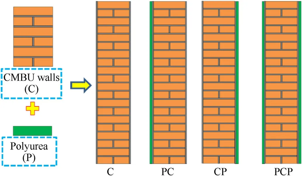
Fig.1. Schematic diagram of the designed wall structures.

Table 1 Material parameters for bricks and mortar [12,25,31].
The brick elements were constructed with staggered joints. In the actual construction, the ground was first tamped and the foundation with a width of 37 cm was built with clay bricks, and then the walls were built on this foundation as shown in Fig. 2(a),(b). In order to ensure the bonding strength and spraying uniformity between polyurea and the wall substrate,the external surface of the wall was troweled with 10 mm mortar,as shown in Fig.2(c).Therefore,the total thickness of the unreinforced masonry wall was 26 cm if the floated coating on both surfaces of the wall was included.
The support device made of angle steel was used to provide back support and restraint for the wall. The supporting device was composed of steel frame and legs, which were made of Q235A carbon steel with a yield strength of 239 MPa,a tensile strength of 430 MPa and an elastic modulus of 209 GPa.The steel frame behind the wall was fixed all around. Therefore, it can be considered that the supporting device composed of steel frame can provide the necessary support and restraint for the wall on four edges. In the test, the bottom of the outrigger was placed on a previously constructed brick foundation shown in Fig. 2 (b). In order to maintain the stability of the foundation of the wall,some cement,mortar and other materials were compacted on the steel frame at the bottom.The purpose of the above measures is to increase the horizontal movement resistance of the support device,so as to prevent it from sliding under the explosive load,which may affect the reliability of the test results.As this is a kind of infilled masonry wall studied in this paper, no additional vertical load is added to the wall. Therefore, the boundary conditions of walls in all tests are similar to those of simply-supported supports.
All the brick walls were cured for more than 28 days before being reinforced with polyurea elastomer. Then the polyurea was sprayed on the surface of the substrate directly by reaction injection molding(RIM) technology to form a protective coating(When spraying, the ambient temperature is closely to 5C), as shown in Fig. 2 (d) and (e).
2.2. Polyurea material properties
The polyurea coating used in this paper is composed of A and B components, and the component A is isocyanate and B is amino compound.The two components are heated and mixed in the spray chamber to form polyurea. Due to the various formula systems of polyurea and the complex chemical reaction process, the mechanical properties of polyurea in different formulations vary greatly. Table 2 enumerates the parameters of polyurea.
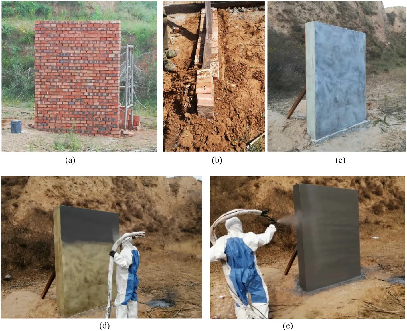
Fig. 2. Construction of polyurea reinforced CBMU walls: (a) Bare clay brick wall substrate; (b) Foundation; (c) Masonry wall with cement mortar; (d)-(e) Polyurea coating reinforcement.

Table 2 Material parameters for polyuria.
In order to explore the dynamic mechanics performance, the stress-strain curves of polyurea materials at 0.001-0.1 sand 1000-6000 sstrain rates were explored by quasi-static tensile experiment and SHPB experiment (the ALT1000 SHPB experimental platform was adopted)respectively,as shown in Fig.3.The indoor temperature of material dynamic mechanical test is consistent with that of field test.
Under the condition of high strain rates (>4000 s), a significant strain rate enhancement effect appears before the end of the stress-strain curve in polyurea(Fig. 3(b)), the yield stress increases with the increase of strain rate.The yield plateau behind the elastic section,which we called the“compaction stage”,indicates that the micropores in the polyurea material are compacted. Likely, the mechanical properties of the last stage are enhanced, which we called the “enhanced stage”. Polyurea is a hyperelastic material,after the dynamic loading process, the inertial action of polyurea shows elastic characteristics when the external load disappears.At the end of the stress-strain curve,there is a small drop.At this stage,the strain of the specimen increases slightly, but the stress decreases rapidly. It can also be seen from the figure that polyurea material has extremely significant strain rate effect, i.e., the stronger the external load, the stronger the material resistance.
Fig. 3(d) shows that the polyurea was subjected to an external tensile load and enters the elastic phase, where the stress-strain relationship increases rapidly. Then an obvious yield point appears on the curve,and the material begins to enter the yield stage.But the yield platform and the strain hardening stage is not obviously enough, and there was only a slight hardening stage. At the same time,it also shows a good strain rate effect in the quasi-static tensile experiment, and the yield stress has an observable change with the strain rate.
2.3. Test setup
The setup of the blast resistance test of masonry walls is shown in Fig.4.The explosive was TNT cylindrical charge,with a basic size of φ 15 cm × 18 cm. The charge weight Wwas 5.0 kg with a density of 1.58 g/cm. The charge was supported by a PVC plastic pipe and placed horizontally at a certain distance from the wall.Its bottom faced the center of the wall and its axis was vertical to the wall.
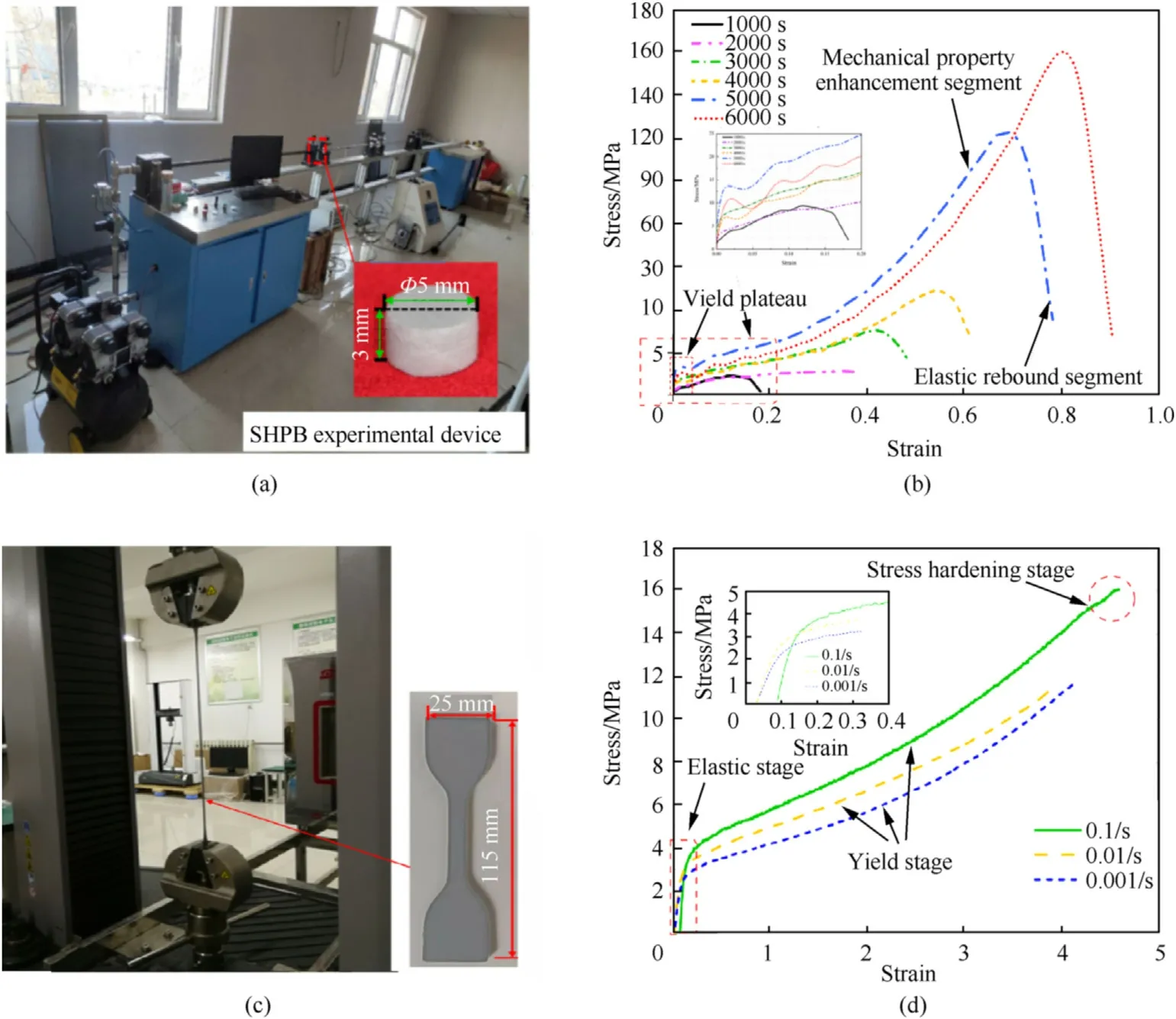
Fig. 3. Dynamic mechanical properties of polyurea: (a) SHPB experimental device and sample;(b) Stress-strain curve from SHPB test; (c) Quasi-static tensile experimental device and samples; (d)Stress-strain curve from tensile test.
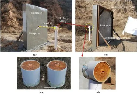
Fig. 4. Experimental setup: (a) Front view; (b) Back view; (c) TNT charge (15 cm in diameter × 18 cm in height); (d) Initiation state of TNT charge.
The stand-off distance(R)refers to the vertical distance between the charge center and the wall center point.In order to realize the different scaled distances[32](Z=R/W),the stand-off was set to 1.5 m,1.0 m and 0.6 m,so the corresponding scaled distances were 0.88 m/kg, 0.584 m/kgand 0.35 m/kg, respectively (The mass of the charge remaining constant while the stand-off (R)changed to produce the required scaled distance). Although the scaled distance of 0.88 m/kgis typically considered to be larger than the limit for the traditionally considered close-in blast[33],it is also smaller than the limit for the far-field blast.Thus it falls into a range where it can have the characteristics of both. The electric detonator was used to initiate the charge at the center of the side which was away from the wall.
The test was carried out separately for bare walls and polyurea reinforced walls. In the first blast event, the unstrengthened walls were exposed to the blast due to 5.0 kg TNT explosive at a standoff distance of 1.5 m, 1.0 m and 0.5 m(UW-1.5, UW-1.0 and UW-0.5).The first two letters of specimen ID represent the type of walls(UW:Unstrengthened wall specimen)and the next numerical value is the standoff distance of charge in m. In the second blast event, the polyurea strengthened walls were exposed to the blast due to 5.0 kg TNT explosive as well. Take “PSW-1.0-F3.0&R3.0” for example,the first three letters of specimen ID represent the type of walls (PSW: polyurea strengthened wall specimen), and the next numerical value is the standoff distance of charge in m. In the last string of characters, F represents the coating on the front face, R means on the rear face; the number after F and R represents the coating thickness. The experiments were carried out one by one with the results well counted and collated.The main characteristics of the tests were summarized in Table 3.
3. Test results
3.1. Response characteristics of unreinforced CBMU walls at different scaled distances
3.1.1. Test of UW-1.5
Fig.5 illustrates the failure mode of the bare wall with a scaled distance of 0.88 m/kg. It is indicated that the unreinforced wall specimen was seriously damaged. There were five broken blocks relatively separated with each other. As shown in Fig. 5 (c), the three wall blocks were scattered in front of the front face, i.e., the wall breaks after explosion loading, and the blocks were scattered in the front after colliding with the back steel frame.The other two wall blocks remained at their original positions, but a wide crack with an angle of about 45to the horizontal plane appeared between them, as shown in Fig. 5 (d) and (e).
The clay bricks of the two parts of the wall block were dislocated greatly, and the maximum displacement was about 7.0 cm. There was no debris splashing in the area behind the rear surface, but a few pieces formed due to the rupture of the floated coat (thefarthest distance was only about 10 cm)were found.In this test,the explosive loading significantly exceeded the bearing capacity of the wall, resulting in the main crack and dislocation of the single wall specimen in a very short time.
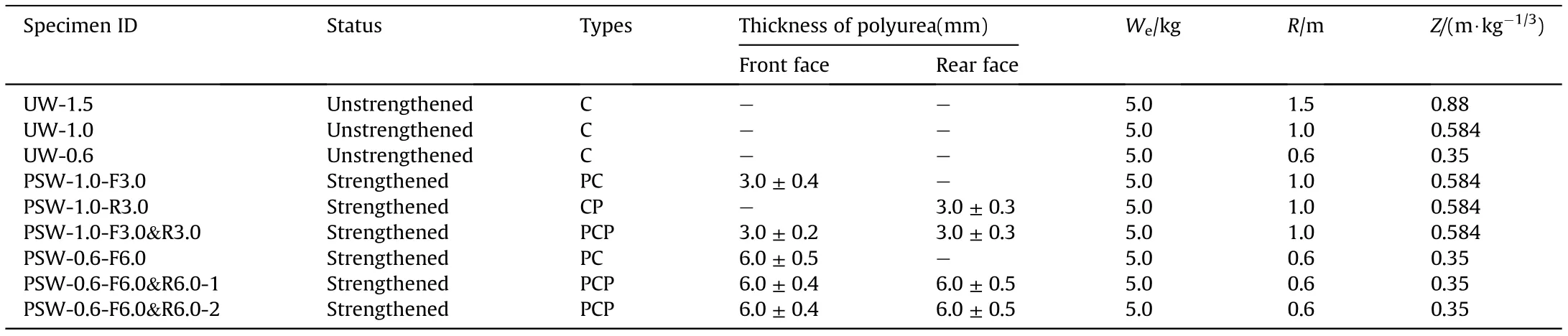
Table 3 Characteristics of the tests.
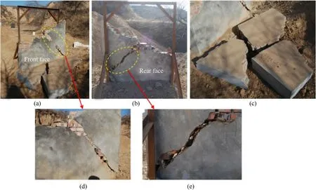
Fig.5. Photos of macroscopic failure of unreinforced CBMU walls(Z=0.88 m/kg1/3,R=1.5 m):(a)Front view;(b)Back view;(c)The large blocks scattered in front of the front face;(d) Crack on the front face; (e) Crack on the rear face.
3.1.2. Test of UW-1.0
Fig. 6 is the failure mode of the bare wall with the scaled distance of 0.584 m/kg. The results showed that the wall was seriously damaged,and the failure mode of the wall was similar to that of UW-1.5. Subjected to explosive loads, the wall was broken into five parts (Fig. 6(a)), and the two relatively complete wall blocks were scattered in front of front face. The other three wall blocks remained in the original positions, but two blocks on both sides flipped over backward obviously.Three penetrating cracks(Fig.6(c,d)) appeared at the lower part of the residual wall block, and the width of the widest crack was 2.4 cm.Compared with UW-1.5,UW-1.0 had obvious debris splashing in the area behind the rear surface of wall, and the debris were mainly whole bricks or large block bricks (Fig. 6 (b)). According to the measurement, the farthest ejection distance of visible debris was about 3.2 m. From the analysis of the experiment pictures,with the decrease of the charge scaled distance, the distribution of the wall debris gradually increased and the distance of ejection was also farther. Moreover,the farther the ejection distance,the smaller the distribution size of debris. Obviously, the blast load on the wall in this test also significantly exceeded its bearing capacity.
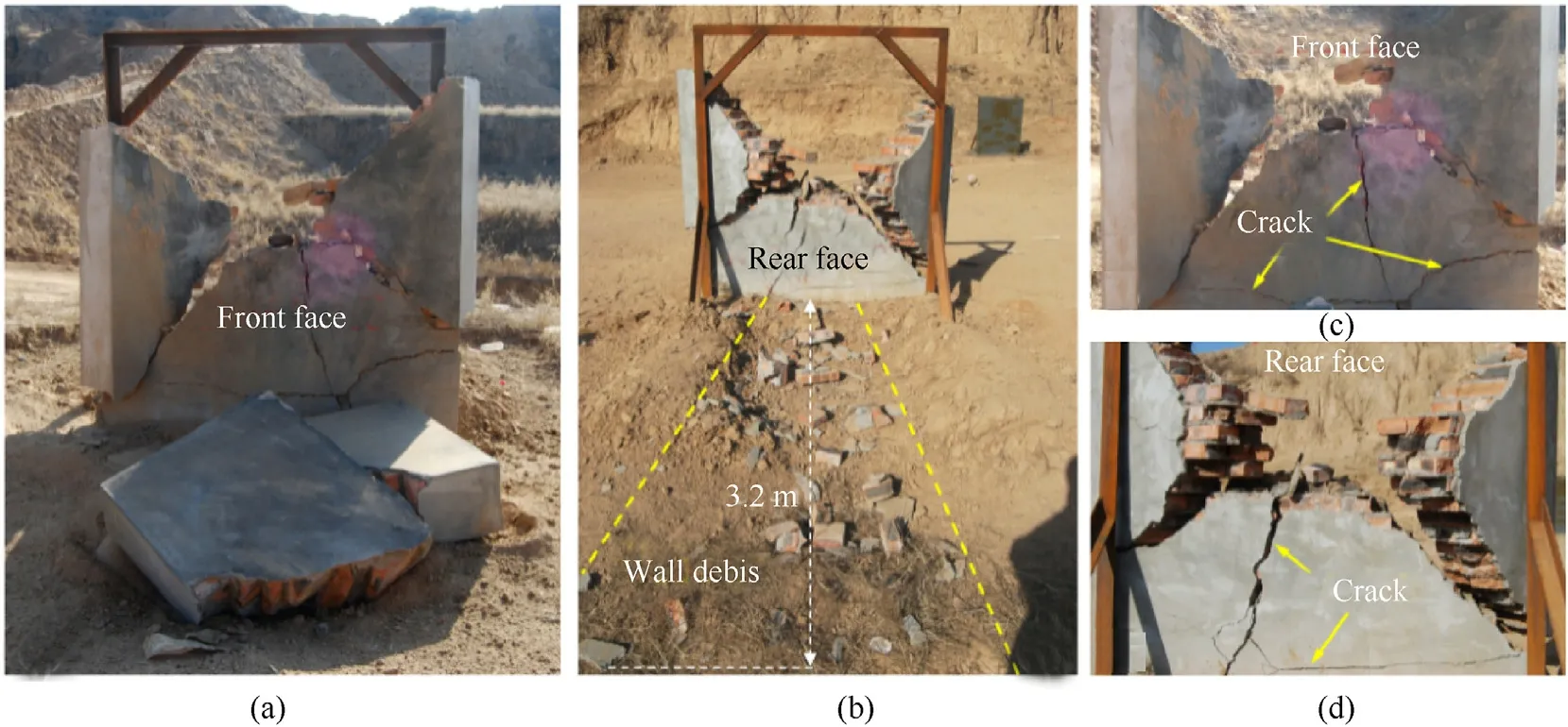
Fig. 6. Photos of macroscopic failure of unreinforced CBMU walls (Z = 0.584 m/kg1/3, R = 1.0 m): (a) Front face; (b) Rear face and debris ejection; (c) Cracks on the front face; (d)Cracks on the rear face.
Fig. 7. Photos of macroscopic failure of unreinforced CBMU wall (Z = 0.35 m/kg1/3, R = 0.6 m): (a) Front face; (b) Back face and debris ejection; (c) Crack on the rear face.
3.1.3. Test of UW-0.6
Fig.7 shows the failure mode of the bare wall at scaled distance of 0.35 m/kg. It was found that the wall specimen was seriously damaged, with a failure mode similar to the previous two experiments. The UW-0.6 wall cracked into six relatively complete parts(Fig.7(a)),and four of them were scattered in front of the front face.The other two blocks remained at the original positions, but the block on the right side flipped backward obviously. There were several cracks on the front and rear faces of the remaining blocks at the lower part of the wall(Fig.7(a,c)).In the area behind the rear surface of wall,obvious debris splashing was found(Fig.7(b)).The farthest ejection distance of the visible debris was about 4.1 m.Compared with the UW-1.0 test results, the fragmentation degree of the wall, number of debris and its ejection distance were significantly increased. In this test, the explosive load on the wall significantly exceeded its bearing capacity, causing complete destruction of the unreinforced brick wall.
3.2. Response characteristics of CBMU walls strengthened with polyurea at different scaled distances
3.2.1. Test of PSW-1.0-F3.0
Fig. 8 demonstrates the failure photographs of the wall reinforced with 3.0 mm thick polyurea coating on the front face. The whole wall collapsed and the rear face was upward. Under the pressure of shock waves and the collision reaction force with the steel frame,the whole wall toppled forward.There was a hole with a visible size of 51 cm × 47 cm(excluding the floated coat) in the central area of the rear face. The deepest part of the hole was exactly the width of one brick(5.3 cm),which means that one layer of bricks was separated from the wall.There were 7 obvious cracks on the rear face of the wall(Fig.8(a)),but the wall did not loose and separate. Behind the rear face, the debris existed which were mainly whole bricks or large brick blocks. Obviously, the original positions of these large bricks were those of the hole.According to the measurement, the farthest ejection distance of debris was about 1.9 m (Fig. 8 (b)). The wall was lifted up and erected on the ground by an excavator (Fig. 8 (c) and (d)) to observe the failure mode of wall’s front face.It can be seen that the polyurea elastomer coating on the front face of the wall was uneven,accompanied by a number of fracture cracks, of which the length of the larger two cracks was about 26 cm and 24 cm respectively(Fig.8 (e)and(f)).
The conclusion could be drawn that the explosive load was higher than the blast resistance bearing limit of the brick wall reinforced by polyurea coating. However, due to the polyurea elastomer material layer on the front face, the connection force between the bricks was improved, the overall coordination between the bricks enhanced, and the deformation of the masonry structure constrained, in terms of both maintaining the structural integrity and reducing the number of back debris.
3.2.2. Test of PSW-1.0-R3.0
Fig. 9 is the failure photographs of the wall reinforced with 3.0 mm thickness polyurea coating on the rear face. The wall was basically intact after the experiment.Under the impact of explosion loads,an oval pit with the size of 11.7 cm×5.3 cm appeared in the floated coat of the wall on the front face, and several cracks extended into the wall edge(Fig.9(a)).After careful confirmation,these cracks only appeared in the floated coat layer, and the brick was not damaged.The polyurea coating on the rear face of the wall had a certain degree of tearing failure(Fig.9(b)).It was confirmed that the floated coat on the rear face of the wall had collapsed.However, due to the existence of polyurea elastomer layer, the floated coat debris did not splash, but was limited to the original position (Fig. 9 (c) and (d)).
In order to observe the shape of the inner clay brick, the polyurea layer on the rear surface was cut and peeled from the wall with a sharp knife.It can be seen from Fig.9(e)that the floated coat on the rear face of the wall naturally fell off and formed a pit of 23.8 cm×32.5 cm.The internal brick wall was only slightly broken and dislocated.
Fig. 10 is the high-speed photographs of the polyurea layer deformation process on the rear surface. Through observation,the polyurea layer experienced several typical stages, such as initial bulge, bulge movement, damage and fracture generation and tear crack propagation.
Compared with the test results of polyurea coating on the front face (Fig. 8), the effect of polyurea sprayed on the rear surface of brick wall was better than that on the front face under the same explosion scaled distance and polyurea coating thickness.
3.2.3. Test of PSW-1.0-F3.0&R3.0
Fig.11 shows the failure photographs of the wall reinforced with 3.0 mm thick polyurea coating on both sides. It is clear that the polyurea layer on the front face is basically intact, with only a few slight cracks due to the material failure caused by the strong impact and compression of explosion loads(Fig.11(a)).The surface of the polyurea coating on the rear face was smooth with slightly bulged,and only a crack with a length of about 26 cm appeared at the lower right side(Fig.11(b)and(c)).It may be caused by complex incident and reflected stress waves concentrated at the edge of the wall support, resulting in the tearing of coating materials.
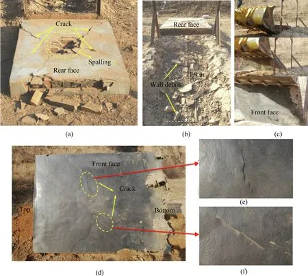
Fig.8. Macroscopic failure of CBMU wall coated with 3 mm thick polyurea on the front face(Z=0.584 m/kg1/3,R=1.0 m):(a)Collapse on the rear face;(b)Debris eject;(c)The front face turned over by forklift truck; (d)-(f) Cracks on the front face.
Fig.12 shows the high-speed photographs of the polyurea layer deformation process on the rear face of the wall.The polyurea layer on the rear face first had a slight bulge through careful observation,and finally had a certain degree of rebound after the stress waves disappeared in the composite wall.The reason is that polyurea is a hyperelastic material, and meanwhile, the explosion load did not reach the plastic deformation stage of polyurea in this deformation process.
In this test, the explosion load did not reach the explosion resistance limit of the brick wall strengthened by polyurea,and the effect of double-sided reinforcement of polyurea on the blast resistance performance of the brick wall is better than that of the single-sided reinforcement.
3.2.4. Test of PSW-0.6-F6.0
Fig.13 displays the failure photos of the wall coated with 6.0 mm thick polyurea on the front face.The whole wall collapsed with the rear face upward,similar to the results of PSW-1.0-F3.0.A hole with a visible size of 80 cm×67 cm appeared in the wall.After the debris in the hole was cleaned, the clay brick in the hole area had completely fallen off, i.e., the depth of the hole crosses the wall thickness direction, but the polyurea layer did not break. The clay bricks in other areas were still firmly bonded with mortar. Debris was found scattered in the area behind the rear surface of the wall,and the farthest flying distance of debris was about 2.4 m (Fig.13(b)). In addition, there were 7 obvious cracks on the rear surface of the wall,among which 4 cracks extended to the side of the wall(Fig. 13 (d)-(g)). From the above experimental phenomena, the explosion load was higher than the blast resistance bearing limit of the brick wall strengthened by polyurea coating when the scaled distance was Z = 0.35 m/kg. However, due to the polyurea elastomer coating on the surface,the connection force between the bricks was improved,and so was the overall coordination between the bricks and the deformation of the whole structure.
3.2.5. Test of PSW-0.6-F6.0&R6.0-1
Fig.14 shows the failure pictures of the wall strengthened with 6.0 mm thick polyurea elastomer on both sides. The wall was still standing on the ground,and the polyurea layer on the front face of the wall had black marks burned by the explosion products. As shown in Fig.14 (c), the polyurea layer in the area near the center failed and broke after the impact of explosion loads, forming an elliptical fracture zone with a size of 44 cm×56 cm,and two cracks extending to the side of the wall appeared.The polyurea elastomer coating on the rear face of the wall was intact without any cracking.However,an obvious bulge can be observed with a height of about 2 cm, as shown in Fig.14 (b)-(d).
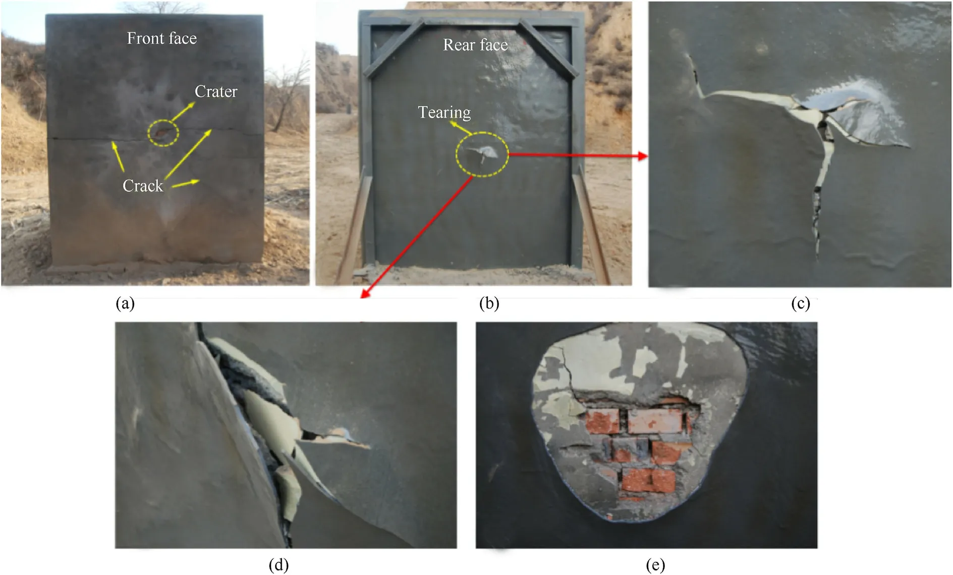
Fig.9. Macro-failure of masonry wall coated with 3.0 mm thick polyurea on the rear face(Z=0.584 m/kg1/3,R=1.0 m):(a)Front face;(b)Rear face;(c)-(d)Crack on the rear face;(e) Deformation of the brick on the rear face with the polyurea layer peeled off.
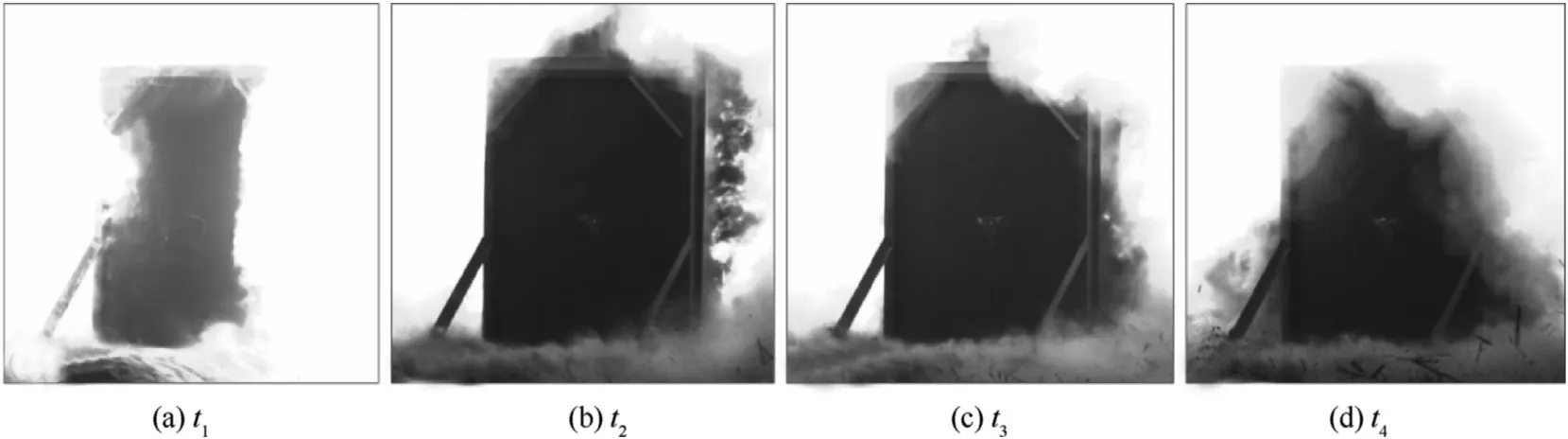
Fig.10. High-speed photographs of the polyurea layer deformation process on the rear surface.
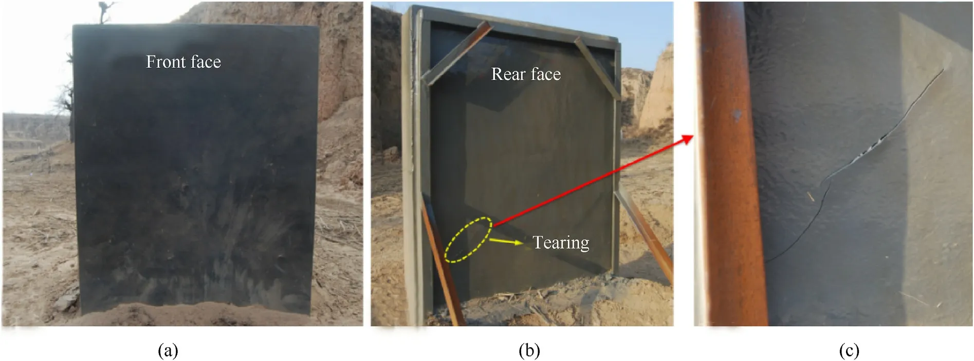
Fig.11. Macro-failure photos of CBMU wall coated with 3.0 mm thick polyurea on both faces (Z= 0.584 m/kg1/3,R =1.0 m): (a)Front face; (b) Rear face; (c)The crack on the rear face.
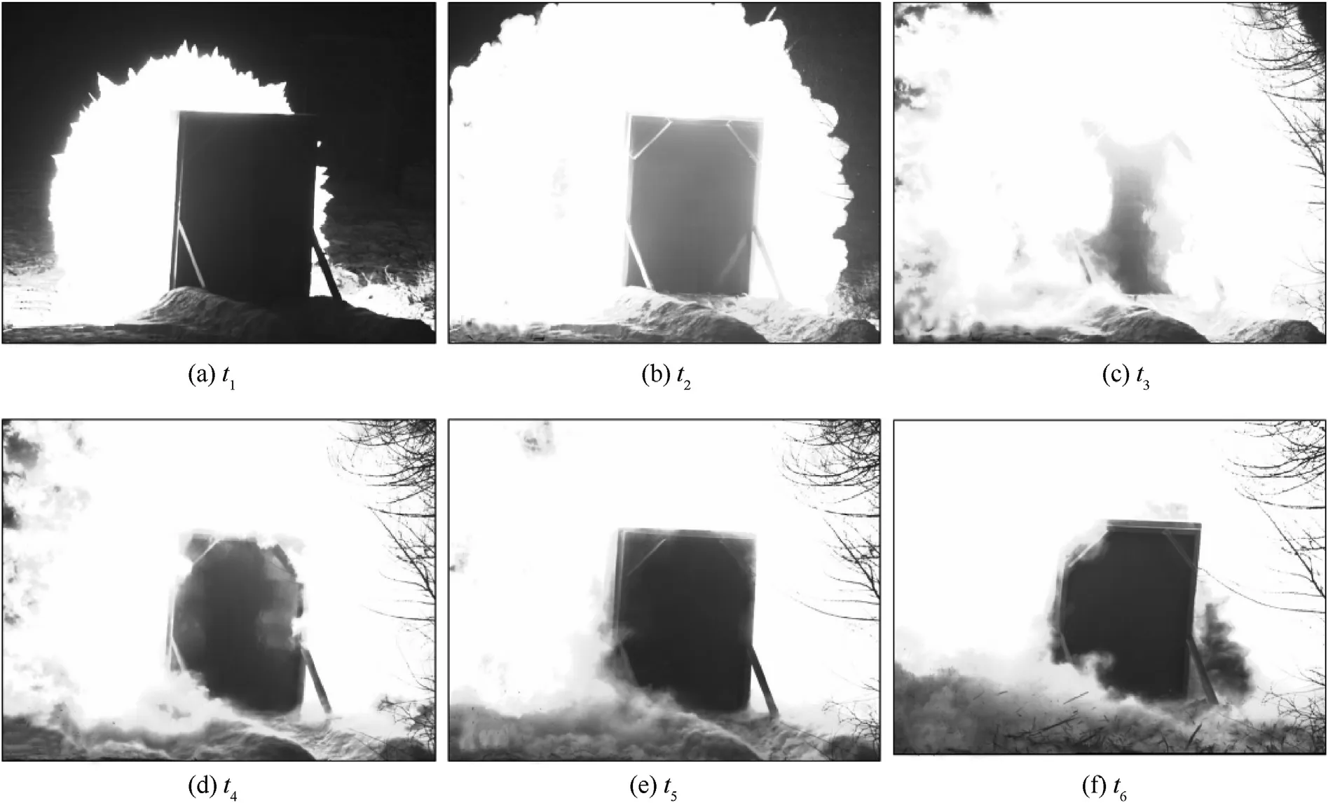
Fig.12. High-speed photos of the polyurea layer deformation process on the rear face.
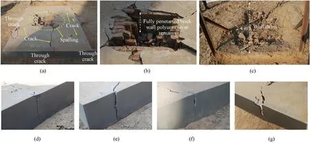
Fig.13. Macroscopic failure photos of the wall coated with 6.0 mm thick polyurea on the front face(Z=0.35 m/kg1/3,R=0.6 m):(a)Rear face;(b)Spalling on the rear face;(c)Debris eject; (d)-(g)Through crack on the wall.
Fig.15 is the high-speed photos of polyurea layer deformation process on rear face. The polyurea coating in the area near the center of the rear face experienced the stages of bulge initiation,bulge growth and expansion, bulge rebound. It was assumed that the internal clay brick might have a certain displacement under explosion loads, thus the polyurea layer experienced a large deformation bulge under the push of brick wall.Because the second blast experiment was carried out later on this wall, no anatomical treatment of polyurea coating was carried out. From the above experimental results, it can be concluded that the explosion load does not reach the explosion resistance limit of the brick wall strengthened by polyurea coatings, and the effect of double-sided reinforcement of polyurea on the blast resistance performance is better than that of the single-sided reinforcement.
3.2.6. Test of PSW-0.6-F6.0&R6.0-2
In order to explore the blast resistance performance of polyurea reinforced brick wall subjected to explosion, the secondary explosion loading experiment of wall specimen(ID:PSW-0.6-F6.0&R6.0-1)was carried out,named PSW-0.6-F6.0&R6.0-2.The charge was still 5.0 kg TNT cylindrical explosive,the central axis of the charge was aligned with the center of PSW-0.6-F6.0 & R6.0-1 wall specimen,and the stand-off distance was also 0.6 m,as shown in Fig.16(a).It was demonstrated that the wall still stood on the ground and maintained a certain structural integrity after the explosive test.As shown in Fig.16 (b), a large hole appeared on the front face of the wall after the second explosion loading. The width of the original two thinner cracks was now significantly increased. The polyurea elastomer layer on the rear face was intact without any cracking.However, compared with PSW-0.6-F6.0&R6.0-1, the bulging range and height of the polyurea layer(11 cm)were significantly larger,as shown in Fig.16 (c) and (d).
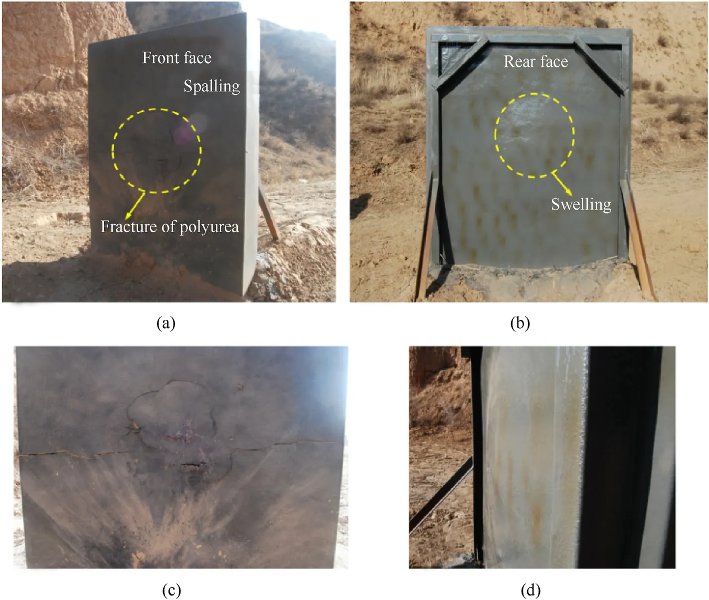
Fig.14. Photos of macroscopic failure of masonry walls coated with 6.0 mm thick polyurea on the front and rear face under the first impact:(a)Fracture of polyurea on front face;(b)Swelling on rear face; (c) Enlarged view of fracture on front face; (d)Side view of swelling on rear face.
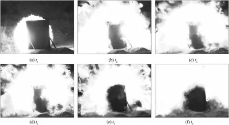
Fig.15. High speed photos of polyurea layer deformation process on the rear face (Z = 0.35 m/kg1/3, R = 0.6 m).
Fig. 17 shows the high-speed photos of the polyurea layer deformation process on the rear face of the wall. It can be clearly seen the expanding progress of bulge, which became higher and larger. And no obvious drop of polyurea bulge was observed.
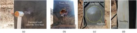
Fig.16. Photos of macroscopic failure of CBMU walls coated with 6.0 mm thick polyurea on both sides under secondary impact:(a)State before secondary explosion(b)Crater on the front face; (c) Swelling on the rear face; (d)Side view of swelling on rear face.
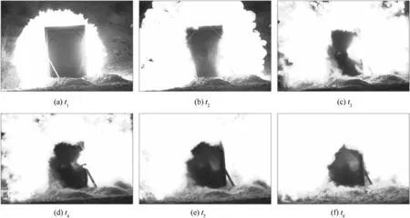
Fig.17. High speed photos of the polyurea layer deformation process on the rear face.
After a carefully observation of the hole on the front face of the wall, crushed clay brick and mortar powder covered the hole’s bottom,as shown in Fig.18(a).The powder was cleaned out of the hole without damaging other parts,as shown in Fig.18(b).Then the actual size of the hole was about 54 cm × 49 cm, with the maximum depth about 22 cm.Obviously,the residual clay brick in the hole had a large displacement backward, and there were obvious dislocations between the wall bricks as well as the wall bricks and the mortar layer.
In order to have a clear understanding of the deformation form of the wall brick, the polyurea coating on the rear face of the wall was cut and peeled off with a sharp knife. It can be obtained from Fig.19(a)and(b)that although some bricks fractured,they were not detached from each other.There was a certain degree of dislocation and protrusion of bricks. The phenomenon explained the reason why the polyurea bulge height and area increased significantly.The peeled-off polyurea coating bonded with the floated coat, which verified that the polyurea materials had good adhesion properties for building materials.
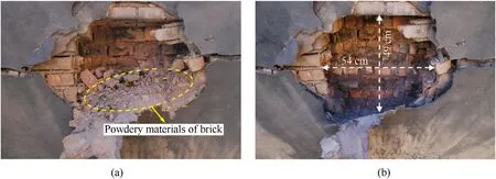
Fig.18. Local failure photos of PSW-0.6-F6.0&R6.0-2 polyurea-coated masonry wall under secondary impact:(a)The hole on front face before clean-up;(b)The hole on front face after clean-up.
4. Analysis and discussion
4.1. Analysis of the macro-failure mode of CBMU wall
According to the test results, the reinforced and unreinforced CBMU walls showed different failure modes under blast loading.These failure modes are closely related to the charge scaled distances, polyurea reinforcement methods and other factors. The failure degree of the wall can be divided into five modes as follows:
D-I: The front surface or rear surface is basically intact with slight damage,and there is no debris splashing behind the rear face.The wall can still play its originally designed structure function,and only modification maintenance on the wall surface is needed.
D-II:Cracks and holes appear in the wall,and there is no debris splashing behind the rear surface; the wall remains intact and not separated, which can still be used.
D-III: There are large cracks and holes in the wall, and debris appear behind the rear surface; the integrity of the wall is maintained, but needs to be repaired for further use.
D-IV: The wall seriously cracked and partially collapsed, and there is no debris splashing behind the rear surface.
D-V:The wall seriously cracked,inclined and partially collapsed,and obvious debris splashing happens behind the rear surface.
Table 4 is the statistical table of the corresponding relationship between the failure modes of brick walls and the test initial conditions. The walls are divided into reinforced and unreinforced walls for detailed damage and failure analysis.
The masonry wall used in this paper is an array of bricks by mortar joints.Mortar is the vulnerable and easily damaged part of the masonry structure, while the clay brick is a solid structure,which is different from the hollow structure of concrete block.Therefore, the energy absorption process caused by the block failure of the hollow structure does not occur under explosion loads.
●Due to the poor tensile strength of the interface between mortar and masonry, the damage generally starts from the mortar joints of masonry,cracks appear and then the bearing capacity of the wall decreases or even loses.Fortunately,the spray polyurea can be strongly bonded to the masonry wall because of its excellent ductility, tensile and shear strength,and the degree of block cracking can be well delayed,so as to improve the blast resistance ability of the masonry wall.
●In the process of bearing explosive loads, bond failure between brick and mortar can be produced in the masonry wall due to different stress conditions of each unit, and oblique crack failure can appear in the brick due to shear force. For the unreinforced wall,the failure of the brick itself is limited,which is mainly caused by the mortar cracking between bricks, namely, the shear slip along the horizontal through joint and vertical joint.
According to the division of failure grades in Table 4, the histogram of damage grades vs scaled distances was obtained as shown in Fig.20.The higher the bar is,the more serious the damage degree of the wall is.It can be seen that the failure grade number of the walls without polyurea coating were high under blast impact at scaled distance of 0.35, 0.59 and 0.88 m/kg. After being strengthened by the polyurea coating, the wall had significantly decreased damage grade under scaled distance of 0.35 and 0.59 m/kg. At the same time, the decreasing range increases with the increase of the scaled distance, and it is also closely related to the increase of the coating thickness. The decreasing range increases with the increase of the scaled distance,and it is also closely related to the increase of the coating thickness. Fig. 21 presents the relationship between the debris ejection distance behind the rear face and the scaled distance obtained from field measurement. In the terms of ejection distance, the thicker the coating, the better the protection of the bare brick wall.
From the division of damage mode, the protective effect of polyurea coatings with different thicknesses and coating method on brick wall at different scaled distances can be qualitatively obtained. Obviously, the deformation characteristics of simply supported unreinforced and reinforced masonry walls are different.The main failure mode is the crater failure in the central area of the masonry wall and the radial through-crack failure. The results showed that the integrity of the unreinforced clay brick wall is completely destroyed by the crater and through-cracks,due to the inertia of motion, the brick wall partially collapses. This phenomenon is more obvious with the decrease of scaled distance. Meanwhile, when the scaled distance is small (Z = 0.584 m/kg,Z = 0.35 m/kg), the debris produced by the unreinforced clay brick wall splash behind the rear face under the explosion load.These debris are mainly clay bricks separated from the wall and floated coat on the surface.The failure mode of the polyurea-coated wall is different from that of the bare wall.
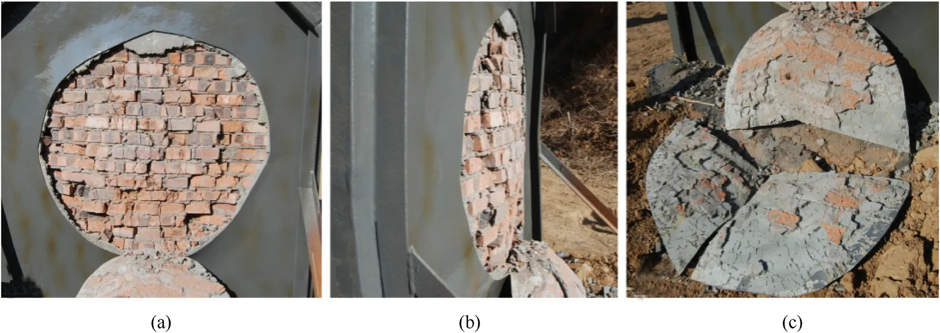
Fig.19. Deformation photos of brick with polyurea coating peeled off (Z = 0.35 m/kg1/3, R = 0.6 m): (a)Elevation view of the exposed wall; (b) Side view of the exposed wall; (c)Closely bonded polyurea coating and floated coat.
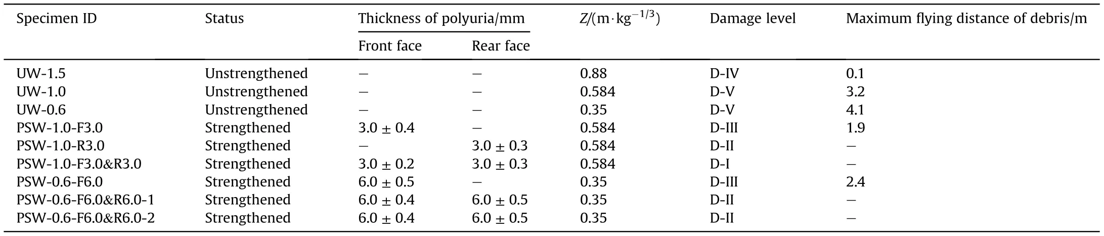
Table 4 Failure modes of walls under different initial conditions.
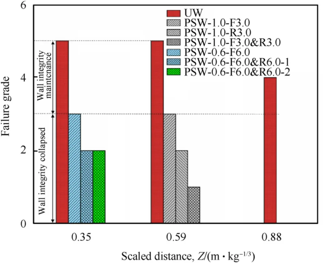
Fig. 20. The histogram of masonry wall failure grades under different scale distance.
Fig.21. Comparisons of fragment ejection distances:3 mm,6 mm and 12 mm were the total thickness of polyurea layers reinforced on the face of walls.
Fig. 22 summarizes the failure forms of the polyurea-coated walls from the experimental phenomena. Among them, the P-t curve represents a typical shock wave load form, while P(t) is the pressure, and t is the action time. With varying positions and thicknesses of polyurea coating,the damage forms of the walls are:Crater on the back, Slightly spalling, Basically intact, Completely through, Internal damage and Dislocation migration. It can be found out that: when the polyurea coating is applied on the front face,the protection effect is not significantly improved,and the rear face of the wall will still collapse and form fragments; the coating effect on the rear face is better than that on the front face;when the scaled distance decreases, the coating thickness should be increased to enhance the protection effect.
4.2. Micro-fracture mechanism analysis of polyurea coatings
In order to analyze the failure mode of the coating under typical loading conditions, the failure morphology of polyurea coatings at typical positions was analyzed by scanning electron microscope(Machine model: Sigma 500). Fig. 23 is the microstructure of the crack taken from Fig. 11(c) (specimen ID: PSW-1.0-F3.0&R3.0) on the rear face of the polyurea coating.It can be seen that the porous structure of polyurea was produced by spraying. Due to the interaction of stress waves, the polyurea coating on the back surface of the wall was torn to form stepped cracks and tear-like cracks, and the extension directions of the two cracks were perpendicular to each other. Fig. 23(a) is the enlarged view of stepped cracks. It is easy to find cluster-like hard segment aggregate and the rod-like morphology of hard segment [34]. This means that the stepped cracks were formed by the shearing crack of hard segment. The enlarged view of tear-like cracks in Fig. 23(b) indicates that the tensile failure of soft matrix,whose fracture morphology is lip-like protrusions, was different from the rod-like morphology of hard segment. Unfortunately, the cluster-like hard segment aggregate was not found in the tear-like cracks. Therefore, it is inferred that the deformation trend of hard and soft segments is different under the impact load. The soft matrix plays the role of tensile bearing,while the hard segment enhances local resistance.
Fig. 24 is the microstructure of cracks on the rear face of the polyurea coating taken from Fig.9(c)(specimen ID:PSW-1.0-R3.0).Due to the lack of reinforcement by polyurea coating on the front face,the number of tear cracks around the pores increases sharply,and some part of the pores collapse. Similar to that of coating on both sides, the tearing cracks are perpendicular to the laddershaped cracks, and the enlarged images show that the stepped cracks present squamous tearing.Obviously,coatings on both sides of the masonry wall can effectively enhance its blast resistance ability.
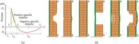
Fig. 22. Failure modes of polyurea-coated CBMU walls: (a) Pressure vs. time plot for blast wave; (b) Typical failure modes.
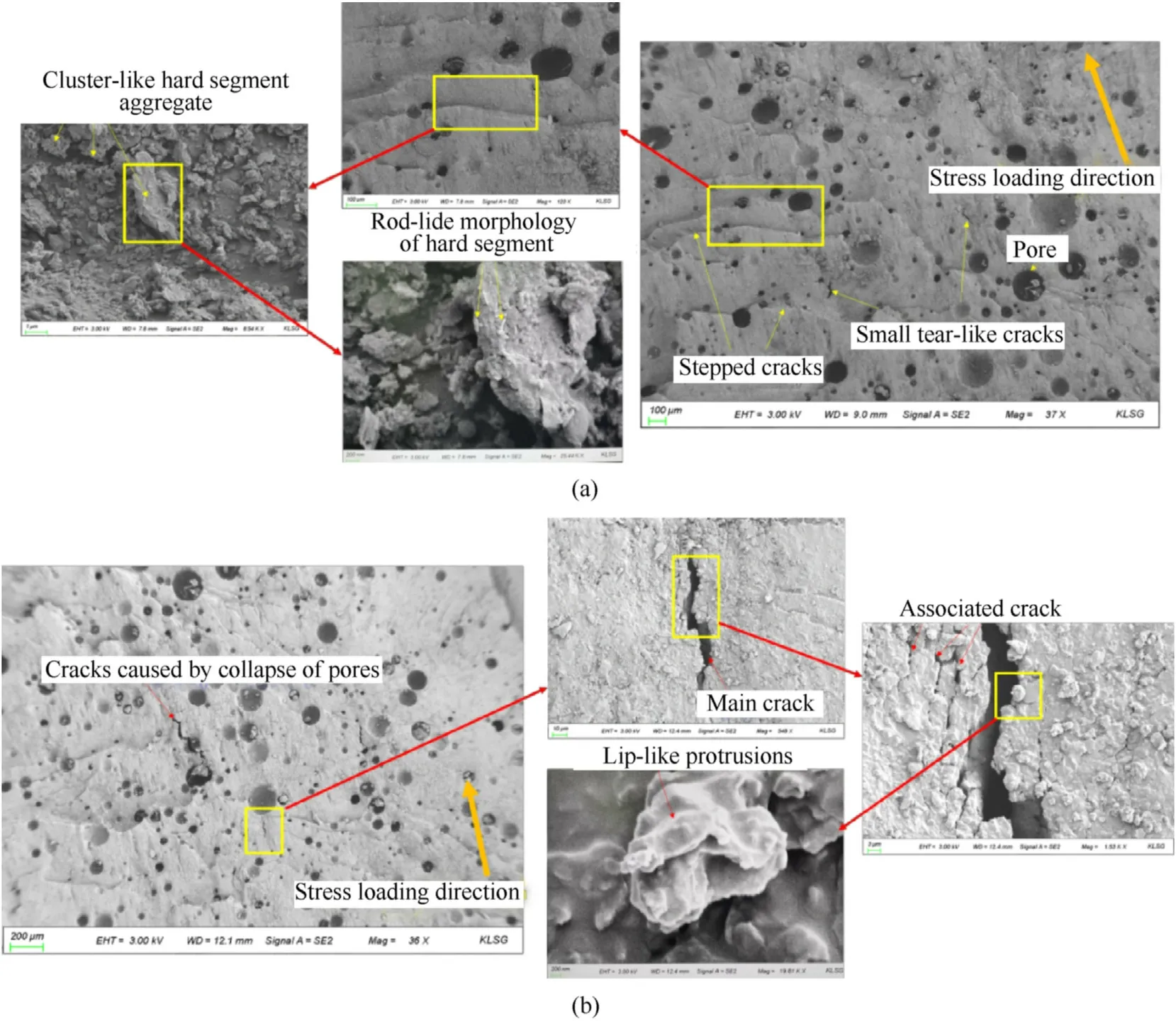
Fig. 23. Microstructure of cracks on the rear face of the polyurea coating: (a) Enlarged view of stepped cracks; (b) Enlarged view of tear-like cracks.
Fig. 25 shows the micro morphology of the cracks of the polyurea coating on the front face taken from Fig.16(c)(specimen ID:PSW-0.6-F6.0&R6.0-2). It was more or less affected by the high temperature loading of detonation products, and the morphology of the front face is different from that of the rear face. Fig. 25(a)shows the serious delamination due to ablation at the center of the explosion on the wall. The number of pores in the field of view increases,and the crisscross gullies interpenetrate in the middle of the pores. After ablation, the boundary was smooth, showing a loose microstructure with coral-like morphology, and some areas was covered by molten condensate. It can be inferred that in this case, the long-range continuous molecular chain has been destroyed, which cannot produce the original anti-deformation effect. In Fig. 25(b), although some stepped cracks can be seen,the microstructure in the field of view has been scoured by detonation products and covered by molten condensation. Thus, the effect of detonation products cannot be ignored in the protection given by polyurea on the front face.
4.3. Pressure characteristics and failure mechanism in walls
Under the test conditions involved in this paper, the failure of the wall can be divided into two categories: the clay bricks separating from each other due to mortar layer failure and the disintegration of the brick wall caused by the crushing failure of the clay brick (like the Specimen ID: PSW-0.6-F6.0&R6.0-2). Therefore, the failure mode mentioned above can be determined by sorting out the failure conditions of mortar layers and clay bricks in the brick wall,and the strengthening mechanism of polyurea coatings can be easily solved as well.
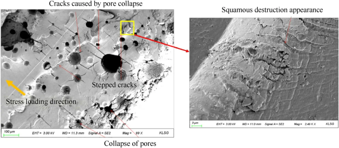
Fig. 24. Microstructure of cracks on the rear face of polyurea coating.
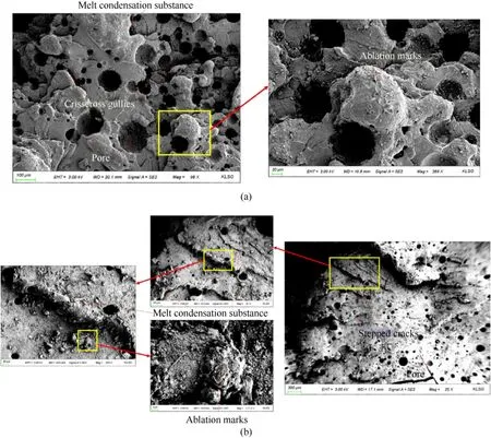
Fig. 25. Morphology of the ablated polyurea coating on the front face: (a) Severe ablation at the core point; (b) Slight ablation far from the core.
The combination of polyurea elastomer and bare wall in this paper can be divided into a two-layer protection structure and a single-layer protection structure. Obviously, the propagation of waves in layered media is complex three-dimensional nonlinear process. It is extremely challenging to analyze the details of the interaction of different waves systematically. In order to qualitatively explain the strengthening mechanism of polyurea coating on masonry walls,the reflection and transmission of one-dimensional stress waves were used to simplify the analysis. Figs. 26 and 27 show the propagation characteristics of waves in different media under single-side and double-side polyurea reinforcement modes respectively. When stress waves propagate between different media, the amplitude of stress wave will change due to impedance matching.
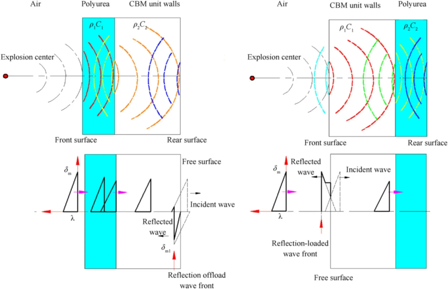
Fig. 26. Transmission and reflection of stress waves in the wall with single-side polyurea coating: (a) Polyurea coating on front face; (b) Polyurea coating on rear face.
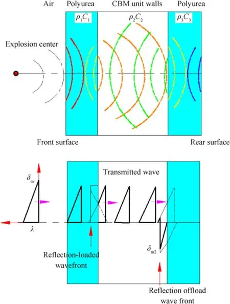
Fig.27. Transmission and reflection of stress waves in the wall with polyurea coatings on both sides.
When the charge explodes at a certain distance, part of its energy propagates outward in the form of shock waves. Through comparative analysis [35], the classical formula of Kinney and Graham [36] (Eq. (1)) has high accuracy in calculating the overpressure value ΔP. In this paper, this equation is selected to calculate ΔPat the front face of the wall. Shock waves then propagate into the brick wall in the form of transmission waves,and there will be reflection overpressure ΔPon the wall surface.ΔPof the vertical impact point (center point) can be acquired according to Eq.(2)[37].When the shock wave is vertically incident,according to the distribution characteristics of reflected overpressure during oblique impact, the increase of pressure after oblique reflection is always smaller than that of normal reflection[37].
The brick wall is regarded as isotropic homogeneous medium in the above analysis.Quite evidently,the material properties of brick and mortar in the masonry brick wall are obviously different(Table 1).When the wave passes into a medium of less impedance(from the wall into the air)the reflection of the wave is in the form of traction. Traction greatly affects the mortar since it is very little resistant to traction. Under high strain rate, the yield strength of bricks will significantly increase[38].Fig.28 shows the axial stressstrain rate curve of the mortar and clay bricks.When the reflected overpressure amplitude exceeds the yield stress of the clay brick or mortar, failure will occur. According to the size of reflected overpressure amplitude, we can determine whether the mortar layer has detached or the brick itself has cracked or crushed.
In light of Eq.(1)and Eq. (2)and the yield limit of mortar layer and clay bricks, the variation of positive reflection overpressure at scaled distances can be obtained as shown in Fig. 29. In the figure,"★" represents the overpressure value of positive reflection under some experimental conditions obtained by theoretical calculation. When the scaled distance is less than 0.9 m/kg, the wall reflection pressure will cause the destruction of the mortar and the separation of bricks.When the scaled distance is less than 0.37 m/kg, the reflected pressure will cause crushing damage of clay bricks on the wall.
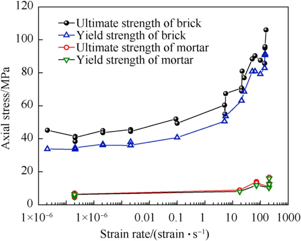
Fig. 28. Axial yield stress-strain rate curve of mortar layer and clay bricks [38].
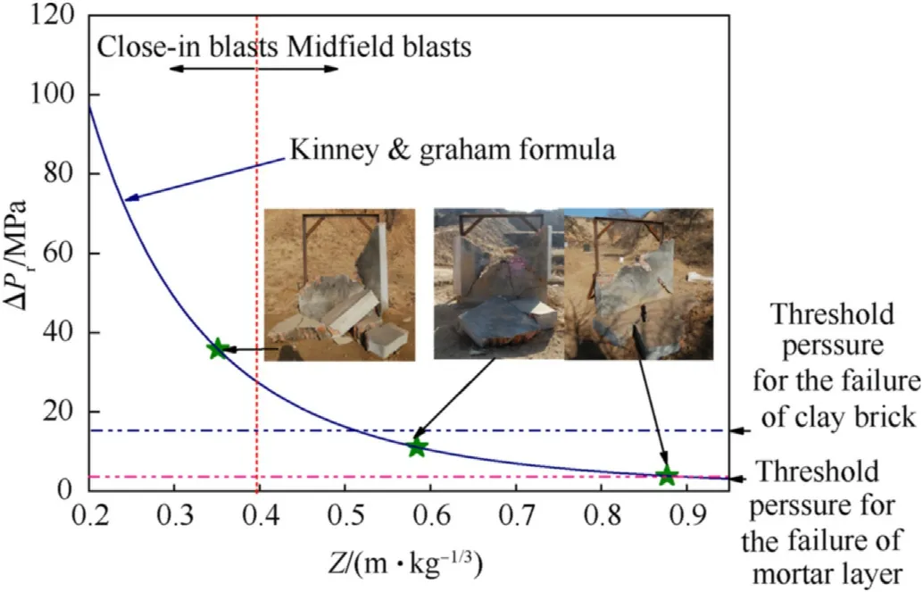
Fig. 29. Variation of overpressure reflected at the center of the front face in the bare wall at scaled distances.
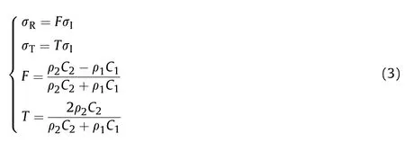
When the polyurea coating is applied on the front face, the stress wave will transmits into the polyurea layer,and the reflected overpressure will appear.Part of the stress wave diffuses due to the material properties, and the transmitted compression wave will propagate into the brick wall. If the collapse and plastic deformation of polyurea are not taken into account, the transmitted compressive wave amplitude in the wall can be obtained according to the stress wave reflection and transmission principle[39]shown in Eq. (3). Where σ, σand σrepresent the incident pressure,reflection pressure and transmission pressure respectively,ρa(bǔ)nd Crepresent the density and sound velocity of the response medium respectively, and F and T represent reflection and transmission coefficient respectively.
For approximate calculation, the material density and sound velocity of polyurea are taken as ρ = 1.098 g/cm, C = 1901.3 m/s[40],and brick and mortar are equivalent to average materials.The material parameters are listed in Table 1.The relationship between the transmission stress and the scaled distance is shown in Fig.30.It can be seen that after the polyurea coating is adopted, the structural impedance matching results could not form the brick wall to disintegrate.When the scaled distance is Z = 0.88 m/kg,the polyurea coating on the front face cannot cause damage to the mortar.
When the stress wave propagates in the wall,its amplitude will attenuate with the increase of the distance. After reaching to the rear face,the tensile wave,with the same magnitude and opposite stress sign as the incident wave, will be produced. The reflected wave propagates into the medium and interacts with the incident wave,and the instantaneous resultant force at distance ξ from the free surface can be written as:
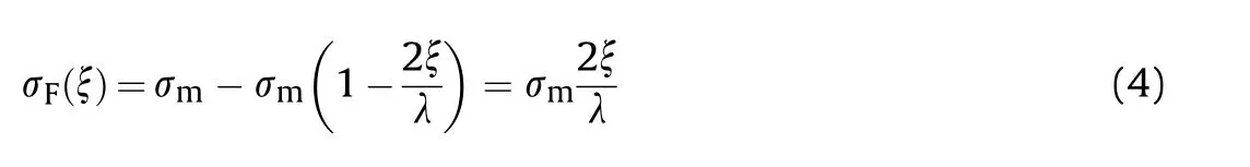
where λ is the wavelength and σis the stress amplitude at the free surface of the wall.Failure occurs when the reflected tensile stress amplitude exceeds the tensile strength of the material. However,the clay brick and floated coat are typical non-tensile materials.The reflection pressure on the free surface is easy to cause damage to the bonding layer and separate the bricks from each other. When the reflected tensile stress of the free face reaches the tensile strength of the material, the bricks will spall off or even fly away.The ejection distance is related to the speed of spalling brick.
According to the calculation methods of stress wave reflection and transmission in different combinations, the maximum reflected stress on the rear face of the wall is shown in Fig. 31. It demonstrates that the wall without polyurea coating is subjected to large reflective tensile pressure from the free surface, and coating on the front and rear faces can reduce the reflected tensile amplitude, and the effect of coating on the rear face was more obvious.
Under the first explosion loading condition, although the internal stress propagation state of the brick wall is not likely to cause the structural disintegration,it may cause pre-damage of the brick and the floated coat to a certain extent, and the yield stress of the material after the pre-damage decreases. Under the secondary explosion loading, it is easy to reach the yield point of the predamaged material and lead to the brick crushing failure.
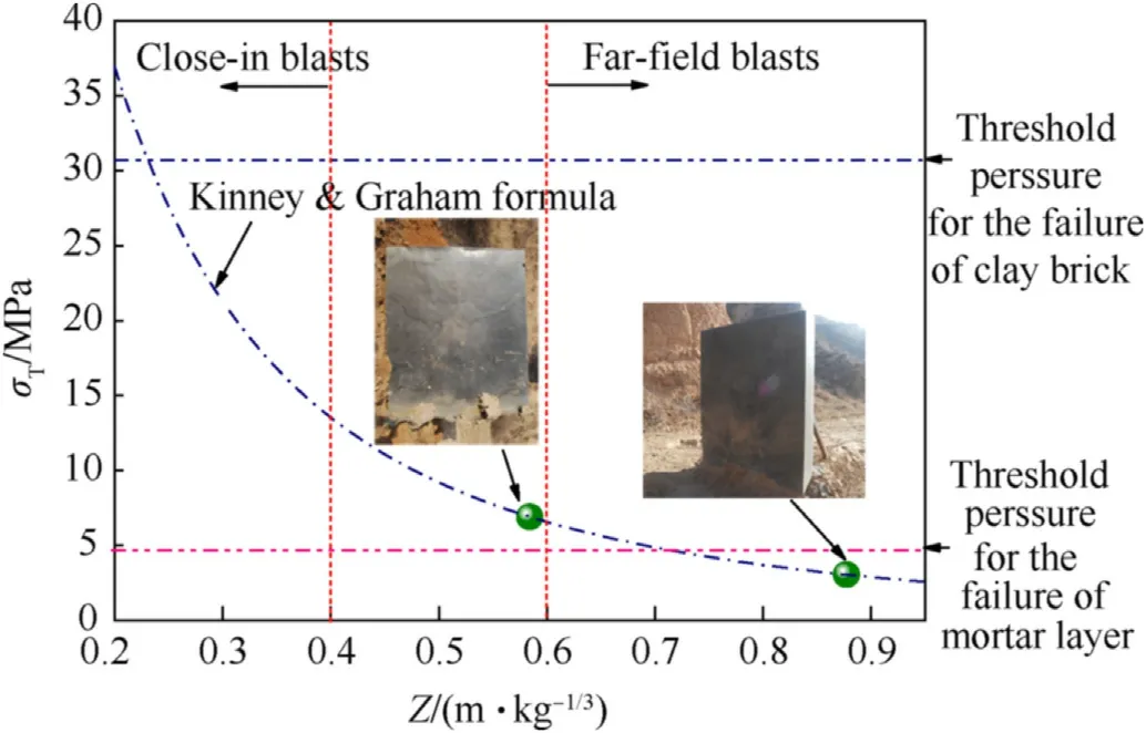
Fig.30. Variation of transmission stress at the central point of the front face of the wall at scaled distances (coated with polyurea).
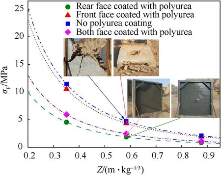
Fig. 31. Variation of maximum reflected tensile stress on the rear face of the wall at scaled distances.
What needs illustration is that the damage basis established in this paper is based on a small amount of experimental data,and the division criterion is only applicable to the specific masonry wall structure. In practice, the size, material, construction method and boundary constraint conditions of brick walls have great influence on the damage effect under blast loads as well as on the presence of openings,transverse walls,and vertical loads.And the failure mode may not be a single mode,but the result of the combined action of various failure modes.
5. Conclusions
In order to obtain the design and application basis of polyurea elastomer in the protection of clay brick masonry unit(CBMU)walls,a series of full-scale tests of response characteristics of 24 cm CBMU walls unreinforced and reinforced with polyurea elastomer under explosion loads were carried out.Through the analysis of the damage mode and the stress wave propagation properties in the wall, as well as the micro-failure mechanism of polyurea coating,the following conclusions are obtained:
(1) For the 24 cm thick bare brick wall,at the scaled distances of Z = 0.88 m/kg, 0.584 m/kgand 0.35 m/kg, which means the loading characteristics of midfield and close-in field loads, the walls all broke into several large pieces scattering on the ground; the fracture section showed that the bricks kept intact in the midfield condition,with only the floated coat separated,while the bricks were also destroyed under the close-in field loads;
(2) The blast resistance ability of CBMU walls was significantly improved by polyurea coating. The test results showed that the resistance effect on the rear face is better than that on the front. With the increase of coating thickness and the scaled distance of explosive, the blast resistance effect represented by damage grade and fragment ejection distance is significantly enhanced. The polyurea-coated wall can maintain its standing state under multiple explosion loading conditions in the case of Z=0.35 m/kgand polyurea coatings on both sides of the wall. Moreover, the adhesion between the polyurea coating and the wall substrate is good;
(3) The stress reflection and transmission characteristics of polyurea and the brick wall multi-media composite structure were analyzed according to the propagation characteristics of stress waves. The main reasons for the failure of the bare wall under the midfield and close-in field loads were the disconnection between the floated coat and the brick,as well as the crushing failure of the brick. In terms of reflection pressure in the wall,the order of coating enhancement effect is back coating,double-sided coating and then front coating;
(4) The microanalysis of polyurea at the cracks showed that,the deformation trend of hard segment and soft segment was different under the impact load: stepped cracks formed by the shearing fracture of the hard segment, while tear-like cracks formed by the tensile failure of soft matrix. If there is high temperature ablation of detonation products, the long-range continuous molecular chain in polyurea may be destroyed, which leads to the loosening of the microstructure,and then causes explosion resistance reduction. This is an important inspiration for the design of flame-retardant and blast resistance polyurea materials in the future.
All data included in this study are available upon request by contact with the corresponding author.
The authors declare that they have no known competing financial interests or personal relationships that could have appeared to influence the work reported in this paper.
This research was supported by the National Natural Science Foundation of China nos. 51978660. The authors would like to gratefully acknowledge this support.
- Defence Technology的其它文章
- Research on DSO vision positioning technology based on binocular stereo panoramic vision system
- Dynamics of luffing motion of a hydraulically driven shell manipulator with revolute clearance joints
- Blast performance of layered charges enveloped by aluminum powder/rubber composites in confined spaces
- Chemical design and characterization of cellulosic derivatives containing high-nitrogen functional groups: Towards the next generation of energetic biopolymers
- Applicability of unique scarf joint configuration in friction stir welding of AA6061-T6: Analysis of torque, force, microstructure and mechanical properties
- Multi-area detection sensitivity calculation model and detection blind areas influence analysis of photoelectric detection target