
Research on DSO vision positioning technology based on binocular stereo panoramic vision system
2022-04-19 04:09:36XiodongGuoZhouWngWeiZhuGungHeHonginDengCixiLvZhenhiZhng
Defence Technology 2022年4期
Xio-dong Guo , Zhou-o Wng , Wei Zhu , Gung He , Hong-in Deng , Ci-xi Lv ,Zhen-hi Zhng ,*
a School of Mechatronical Engineering, Beijing Institute of Technology, Beijing,100081, China
b Department of Architectural Engineering Technology, Vocational and Technical College of Inner Mongolia Agricultural University, Baotou, 014109, China
Keywords:Panoramic vision DSO Visual positioning
ABSTRACT In the visual positioning of Unmanned Ground Vehicle(UGV),the visual odometer based on direct sparse method (DSO) has the advantages of small amount of calculation, high real-time performance and high robustness,so it is more widely used than the visual odometer based on feature point method.Ordinary vision sensors have a narrower viewing angle than panoramic vision sensors, and there are fewer road signs in a single frame of image, resulting in poor road sign tracking and positioning capabilities, and severely restricting the development of visual odometry. Based on these considerations, this paper proposes a binocular stereo panoramic vision positioning algorithm based on extended DSO, which can solve these problems well. The experimental results show that the binocular stereo panoramic vision positioning algorithm based on the extended DSO can directly obtain the panoramic depth image around the UGV, which greatly improves the accuracy and robustness of the visual positioning compared with other ordinary visual odometers.It will have widely application prospects in the UGV field in the future.? 2022 China Ordnance Society. Publishing services by Elsevier B.V. on behalf of KeAi Communications
1. Introduction
The key technology of UGV safe driving [1] can be divided into four parts:environment perception technology,precise positioning technology, decision and planning technology, control and execution technology[2].Among them,precise positioning technology is the core of the entire UGV technology and one of the key tasks of environmental perception [3], which plays a vital role in the safe driving of UGV.The working environment of UGV is rarely in a static environment, usually most of the work is in some complex and highly dynamic environments.
Vehicle self-positioning can be achieved in many ways,including signal-based positioning[4].The typical representative is GNSS positioning, that is, global satellite navigation system. Dead reckoning-inertial measurement unit (IMU), Infer the current position and azimuth angle according to the position and azimuth angle of the previous moment. Environment feature matching,based on lidar/stereo vision positioning, using the observed features to match the features stored in the database, the current position and attitude of the vehicle can be obtained.
With the rapid development of computer vision and image processing technology,stereo vision has been widely used in robot navigation, intelligent manufacturing, intelligent robots and other fields [5-7]. As a necessary and cost-effective passive sensor system, ordinary vision system is widely used in UGV. However,limited by the optical principle of the see-through lens,only a local area in the environment can be observed.Therefore,the amount of environmental information obtained by the vehicle is very limited,and the depth information of the environment cannot be obtained by a single ordinary vehicle vision system [8]. With the rapid development of UGV technology,a single vehicle vision system can no longer meet the needs of large-scale, large field of view and integrated imaging. Compared with the ordinary vehicle vision system, the panoramic vision system can effectively expand the perception range of the vision system [9], which is common in many optical applications. So, the panoramic vision system [10,11]gradually appears in the field of UGV technology [12].
Visual odometry can be considered as part of the visual SLAM technology. The current research direction can realize the method from the front end and restore the dense classification of map points, as shown in Table 1.
From the back-end implementation method, it can be divided into filter-based methods and nonlinear optimization methods.The method of using filters is generally sparse method, such as SVO,MSCKF, ROVIO, etc. Non-linear optimization methods are: OKVIS,VINS, ORB-SLAM. In the field of computer vision, the most classic algorithms for the front end of the visual slam are the feature point method and the direct method.
The feature point method [13] completes the matching of feature points by calculating the key sub and descriptors of the extracted feature points in two or two frames of images, thereby giving the pose changes between the two frames of images,and by reprojection the feature points to construct the residual term.The feature point method to solve the pose transformation is to first calculate the relationship between the camera and the map point,and then calculate the camera pose based on this relationship.The direct method [14] bypasses the extraction and calculation of feature points, and directly constructs the residual term by performing pixel intensity (luminosity) on the two frames of images,And the solution to the change of the camera's posture is to solve the non-linear optimization problem of the map point and the camera's posture at the same time.
Regardless of the direct method or the feature point method,an ordinary perspective camera is usually used to obtain images and perform calculations.The advantage of using a perspective camera is that there are more researches on the related camera model and distortion correction,it is easier to process the image with various computer vision algorithms,and the front-end part is less difficult to implement. However, perspective cameras also have the following disadvantages:
(1) The range of obtaining information around the environment is limited, generally concentrated within 90of the horizontal field of view,rarely exceeding 180,depending on the special lens design method, the maximum can reach 250,but it is limited by optical principles and lens design Horizontal, large image distortion and complex imaging model.The panoramic vision system can easily achieve horizontal 360-degree surround coverage.The vertical field of view can reach more than 100and the vertical field of view can be controlled by designing the shape of the mirror.
(2) The limited horizontal field of view also causes the image quality to be degraded due to fast motion when the vehicle is turning and other rotating scenes. For a panoramic vision system, as long as it does not rotate quickly in place, there will be areas with a relatively low rotation speed and better image quality in the entire surround view image.This feature also helps to improve the accuracy and robustness of the algorithm.
(3) During the rapid movement of the vehicle,the motion speed of the extracted image information points is very fast, and the same environmental point appears in the image sequence very few times. In the joint optimization ofmultiple frames of images,the related geometric constraints will be weakened, and the optimization results will also become worse.

Table 1 General visual SLAM method classification.
Since the origin of the ordinary perspective camera is earlier than the panoramic camera, the current visual odometry mainly focuses on the research of the ordinary camera [15], while the research based on the monocular panoramic visual odometer and the binocular stereo panoramic visual odometer is less. However,with the rapid development of unmanned vehicle technology,due to the narrow viewing angle of ordinary vision cameras, there are fewer road signs in a single frame of images,resulting in poor road sign tracking and positioning capabilities, which severely restricts the development of visual odometry [16]. However, panoramic vision has the characteristics of a natural 360large field of view,integrated imaging, etc., which makes it possible to obtain a large amount of rich and complete environmental information at one time, which greatly improves the tracking and positioning capabilities of road signs. Therefore, the binocular stereo panoramic visual odometer[17]will be the main technology that the UGV will rely on for precise positioning in the future.In the visual odometry based on the feature point method,the corner points in the image are often used as feature points due to their good feature invariance. In the panoramic vision image, the corner points are often distorted and deformed and lose their geometric invariance.Therefore, the feature point extraction and matching algorithm used in the feature point method is difficult to extract and match the correct feature point pair in the panoramic vision image.For the direct method that does not use the feature point method for matching, the panoramic image can be better adapted.
In recent years,many single-sensor or multi-sensor fusion visual odometers have emerged. Cai J, Luo L, Hu S [18]. used RGB-D to conduct direct sparse algorithm research.Shin Y,Park Y,Kim A[19].used lidar and vision camera to complete the direct algorithm SLAM. Zhang N, Zhao Y [20]. used vision combined with IMU measurement data to construct a monocular visual mileage calculation method.Ban X,Wang H,Chen T et al.[21]used deep learning to complete visual odometry.Lu J,Fang Z,Gao Yet al.[22]and Lange M, Raisch C, Schilling A [23]. complete visual odometry by extracting line features of the image. Luo X, Tan Z, Ding Y [24].Construct visual odometry by extracting point features and line features in the image.Xu H,Cai G,Yang X et al.[25]used a method of separating static and dynamic features to construct visual odometry. Meng X Y, Sun B [26]. proposed a visual odometer, but the visual odometer is only an online Kitty running data and failed to be tested on an offline unmanned vehicle, which has certain limitations in the perception of the environment.
Visual odometer is a kind of higher price sensor that scholars have studied most in single sensor odometer. Scholars have also done a lot of pure visual odometry work. Chen M, Tang Y, Zou X et al. [27,28], Won C, Seok H, Cui Z et al. [29] used multi-vision camera stitching for 3D perception and reconstruction, but multivision cameras Splicing will bring a huge amount of data, which has a great impact on the real-time performance of the system.F¨orster C, Zhang Z, Gassner M et al. [30] proposed a semi-direct visual odometry, but the algorithm is only suitable for monocular vision and multi-camera splicing omnidirectional vision models. J.Engel, V. Koltun, and D. Cremers [31]. studied DSO based on ordinary vision, but this DSO is only suitable for ordinary vision, not suitable for binocular ordinary and panoramic. Wang T, Tan N,Zhang C et al. [32] proposed a visual tracking method based on sparse representation, but this research is only applicable to ordinary visual tracking.Matsuki H,Stumberg LV,Usenko VC et al.[33]proposed a monocular visual odometry based on a fish-eye camera,but this method is only suitable for monocular fish-eye cameras.
The previous visual odometer mainly focused on the research of ordinary visual odometer and multi-camera splicing visual odometer, and multi-camera splicing has a relatively large amount of data generated by multiple cameras,which has a great influence on the real-time positioning of unmanned vehicles. Therefore, there are few researches on unmanned vehicles, and there are few researches based on the catadioptric panoramic visual odometry based on unmanned vehicles (If there are no special instructions below, the panoramic visual odometer represents the catadioptric panoramic visual odometer.). Based on the research of ordinary monocular vision DSO, this paper completes a set of binocular stereo panoramic vision DSO for real-time positioning of unmanned vehicles.
2. Methods
The most classic visual odometer based on the direct method is the DSO algorithm proposed by Dr. Jakob Engle [31] in the Computer Laboratory of the Technical University of Munich in 2016. In terms of classification, DSO is a sparse direct method of nonlinear optimization. This paper adopts DSO as the calculation method of visual odometer to improve the traditional DSO. By adding the model of the panoramic vision system, this paper expands the monocular ordinary vision DSO to the monocular panoramic vision DSO, and finally expands the monocular panoramic vision DSO to the binocular stereoscopic panoramic vision DSO.
The FullSystem part mainly includes most of the core algorithms of DSO,in which the Coarse Tracker is responsible for matching the latest keyframes and calculating the residual of the current points after matching.CoarseInitializer is responsible for the initialization of the whole system, including the initialization of residual terms,the calculation of Hessian matrix block, the derivation of photometric error, and the judgment of whether the initialization is successful.Hessian block includes the creation and release of Frame Hessian structure, and the coordinate transformation matrix and photometric affine function of points are calculated according to two Frame Hessian structures.ImmaturePoint is responsible for the maintenance of map points and the determination of inverse depth in the initialization process. In the process of movement, the immature map points are tracked, and the immature map points are transformed into mature map points. PixelSelector is responsible for pixel selection.Residual mainly includes the calculation of residual term between two frames and Jacobi J. Optimization Backend is the part of backend optimization.Accumulate SCHessian computes the Hessian matrix.Utils is mainly used to read data sets and correct image distortion. IOWrapper is responsible for the display and output of results.
The code framework and algorithm flow of monocular DSO are shown in Fig.1 and algorithm 1.The initialization flow of algorithm 1 is explained in algorithm 2 separately.
In monocular DSO, the energy function of each frame is as follows:
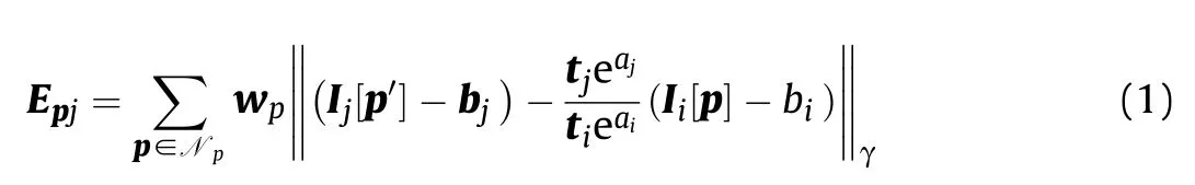
where Iand Iis the image after photometric calibration[34].pis the point p according to the inverse depth d.‖·‖represents Huber loss function,to prevent the energy function of residual error from growing too fast with photometric error. Nis the neighborhood point(see Fig.2 for the distribution mode)when the weighted sum of squares of error is calculated for p point.tand tare the exposure times of images Iand I.wis the residual weight(It used to weight the residual terms constructed by pixels in different positions).?I(p)is the pixel gradient and c is a constant,as shown in Eq.(2).
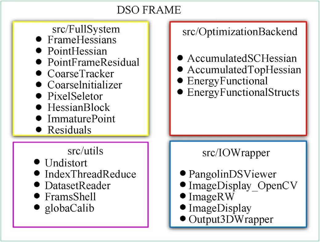
Fig.1. Monocular DSO code framework.
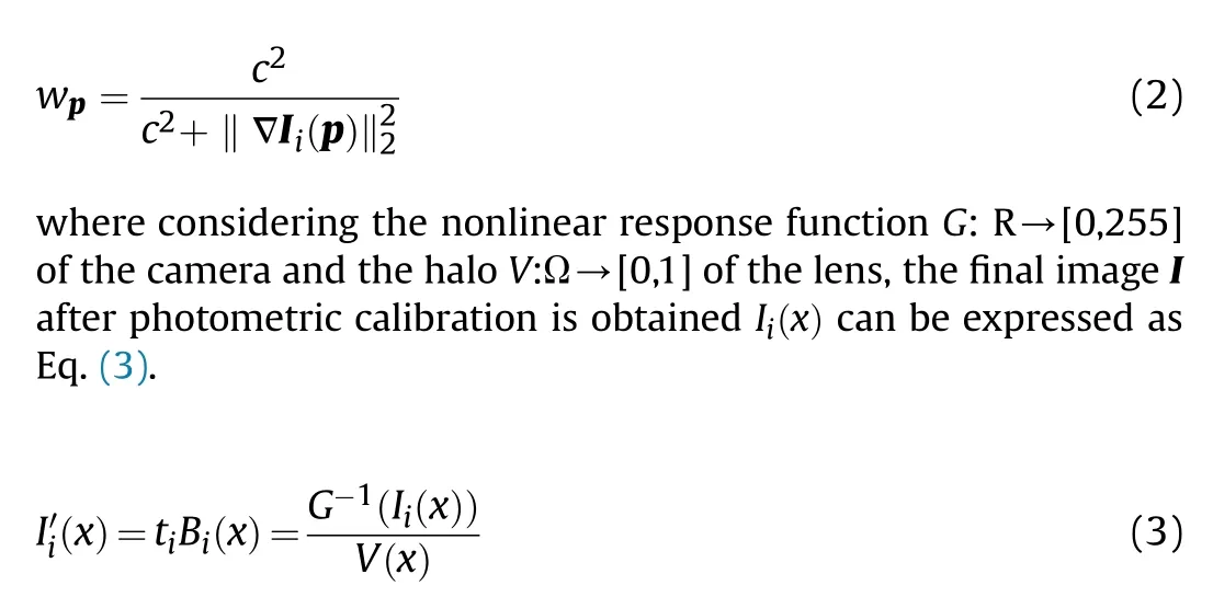
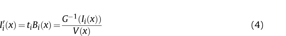
Among them, Band Iis the radiation intensity and pixel intensity of the i-th frame image, tis the exposure time of the i-th frame. The model parameters G: R and V: Ω of photometric calibration can be calibrated by Eq. (4).
In Eq. (1), p and pare the corresponding relations between adjacent i and j frames, and the relations are as follows:
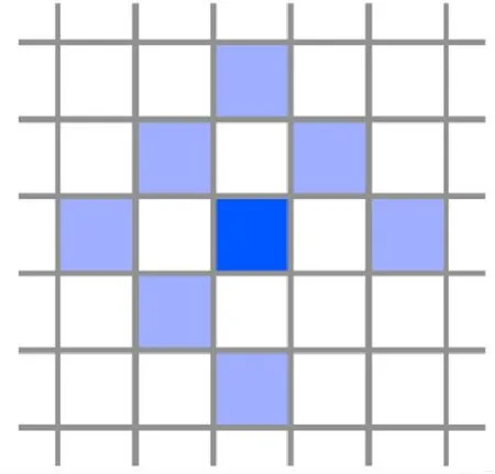
Fig. 2. Np mode diagram.
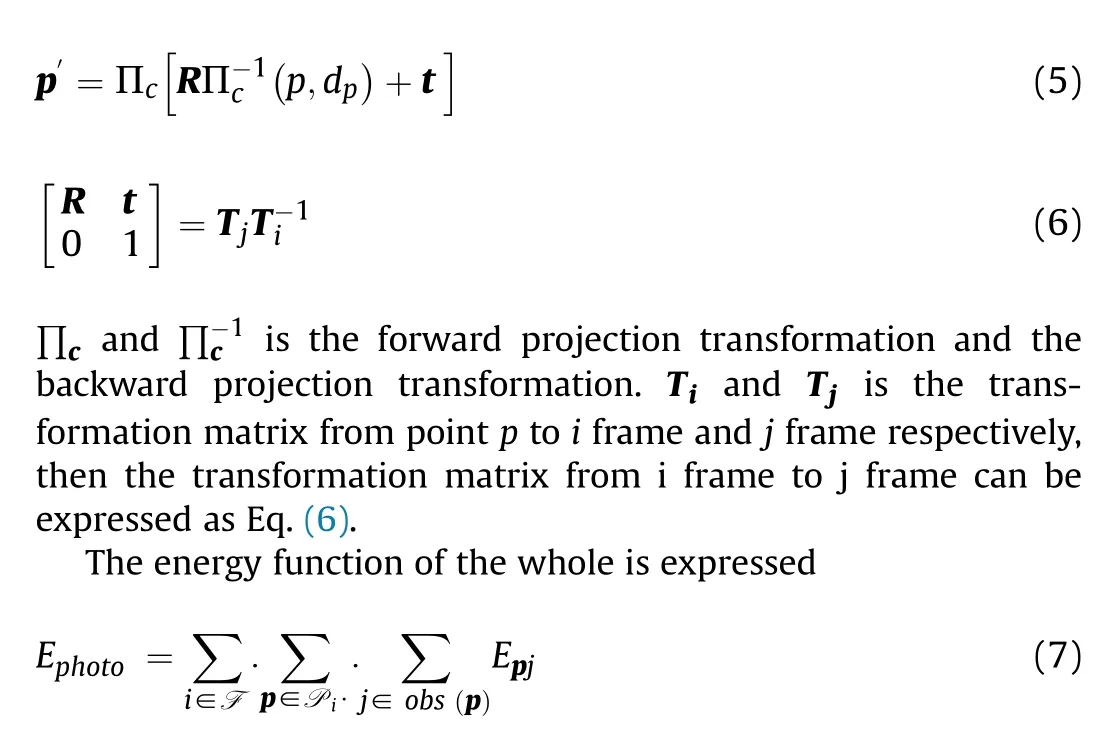
F is the set of all images, p is all the points in the set of Pin frame i, and j is all the images where point p can be observed. In monocular DSO, multiple energy functions as shown in Eq. (7)constitute a window. Generally, a fixed number (6-7 keyframes)will be maintained in the whole window, and the back end will optimize the keyframes in this window. In the process of running the algorithm, the key frames inside the window are added and deleted continuously, which is also called edge. Fig. 3 is a factor diagram between the key frames in the window and the observed map points.
Fig. 3 is the factor graph between the key frames and the observed map points in the window (map optimization). Pt1: din the blue ellipse represents: the inverse depth of the first frame,and so on. E2 in the orange rectangle represents: the residual items formed by projecting the map points in the first frame of image to the second frame of image,and the following numbers are deduced by analogy.The KF1 in the purple rectangle represents the first key frame, where Trepresents the transformation matrix from point p to the first frame of image, aand brepresent the affine brightness and brightness of the first frame of image,respectively, and the following numbers are deduced by analogy.Factor graph for the direct sparse model. Example with four keyframes and four points; one in KF1, two in KF2, and one in KF4.Each energy term (defined in Eq. (1)) depends on the point's host frame (blue), the frame the point is observed in (red), and the points inverse depth(black).Further,all terms depend on the global camera intrinsic vector c, which is not shown.

Fig. 3. Monocular DSO factor diagram.
After the global energy function is obtained, the Gauss Newton method is used for nonlinear optimization. In the optimization process, H =JWJ is used as the approximation of the secondorder Hessian matrix. In the process of calculating the global energy function, it is necessary to find the Jacobian matrix for the energy function.
Binocular DSO is extended based on monocular DSO. The main difference between binocular DSO and monocular DSO is that the initialization process does not need to initialize the depth value in monocular DSO randomly,and the initial depth value is obtained by using binocular stereo matching directly. When a point in a key frame is added to the window for optimization, its inverse depth needs to be updated continuously, so that the depth is improved Information becomes more and more important. In the case of monocular DSO, due to the randomness of the initial value of the depth information,the variance is bound to be very large[35,36]for Monocular Visual Odometry. Computer Vision. In the case of binocular DSO,a better depth estimation can be obtained directly to improve the tracking accuracy. At the same time, in monocular DSO, the scale information of the whole system cannot be estimated, and binocular DSO can get the absolute scale information through a fixed baseline length, which also makes the visual odometer meaningful.
Since binocular DSO is based on monocular DSO, its basic principle and formula derivation are basically the same as monocular DSO.Different from monocular DSO,because binocular stereo matching is added to binocular DSO, the whole energy function increases the binocular matching error term relative to monocular DSO.

Fig. 4 is a factor diagram of binocular DSO, the left box in the factor graph represents 4 key frames,the blue ellipse represents the 5 observed map points, the orange long square represents each energy function,and they are all associated with 1 map point and 2 key frames, the blue line Represents the constraints from the key frame,the red line represents the constraints between the left and right cameras,and the gray line represents the constraints from the observed map points corresponding to the key frames.
The binocular stereo panoramic DSO only needs to extend the perspective camera model of the binocular DSO to the panoramic model. The luminosity calibration has nothing to do with the camera model, only the position of the pixels in the image, so the luminosity calibration is directly performed on the panoramic image,and the corrected image is passed to the back end.
In the binocular stereo panoramic DSO, the energy function of each frame is
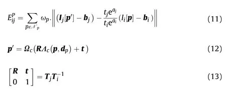
where the projection transformation of points p and ps the projection transformation in the panoramic vision system,Ω(·) is the forward transformation relationship from the vision camera to the map point,Λ(·)is the reverse transformation relationship from the map point to the vision camera,R and t are respectively from the i frame the rotation matrix and translation vector to frame j.
The overall energy function of the binocular stereo panoramic DSO can be concluded from the above equation shown in Eq. (14),and the final position transformation relationship can be obtained by optimizing it [40]. As time goes by, the algorithm will jointly optimize a limited (5-7) key frames in the sliding window, and finally get the optimized trajectory.
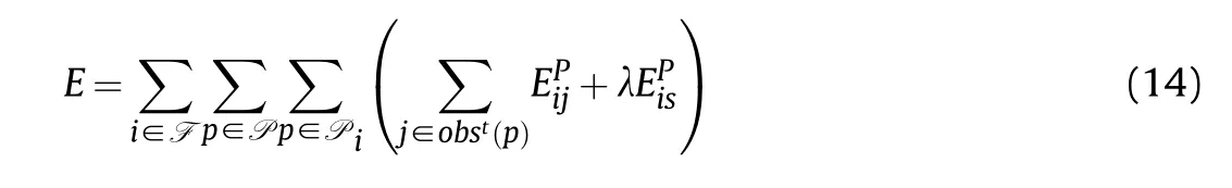
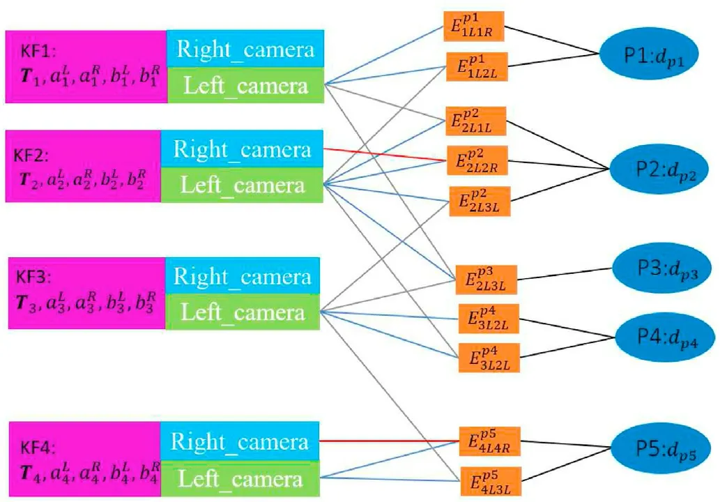
Fig. 4. Binocular DSO factor graph.
where is the balance coefficient,used to adjust the energy function in the binocular DSO and the energy function of the binocular stereo matching error residual term.
3. Experiment verification
3.1. Experimental setup
(1) Experimental location: Beijing Institute of Technology experimental area(Nanyuan).
(2) Experimental equipment: UGV perception platform, binocular stereo panoramic vision system,binocular stereo vision system, polarized Vision System, ZED Vision System, Integrated inertial navigation system, LIDAR, industrial computer, and other equipment.
(3) Experimental evaluation index: The binocular stereoscopic panoramic vision system has higher robustness and positioning accuracy than the binocular stereoscopic vision system in terms of perception and positioning.
(4) Experimental method:Let the UGV drive on the preset route,the binocular stereo vision system, the binocular stereo panoramic vision system, the Integrated inertial navigation system, and LIDAR collect and store data at the same time.Replay all experimental data offline at the original rate, run the data and algorithms that need to be tested,calculate the UGV operating trajectory,then compare each trajectory with the high-precision trajectory generated by the Integrated inertial navigation system and LIDAR fusion, and compare the results analyze and draw experimental conclusions.
During the experiment, the UGV drove according to the preset route in Fig.6,and collected and stored the data at the same time.After completing each driving route, return to the starting point and repeat the experiment for a total of 5 consecutive times. The driving speed is about 10 km/h, 10 km/h, 15 km/h, 25 km/h, and 30 km/h.
The experimental equipment configuration is as follows: Integrated inertial navigation system includes OXTS and BEIDOU satellite receiver,OXTS is set to external receiver state,the positioning signal of BEIDOU receiver is used as the external positioning data input source, and the GPS antenna placed on the roof is used for heading estimation. Combined with the accelerometer and gyroscope of OXTS built-in IMU,the 24 order EKF algorithm is used for fusion estimation, all the navigation information, including the ground unmanned platform odometer and longitude and latitude,is finally output at the rate of 100 Hz. In the integrated inertial navigation system, the time synchronization signal source of the sensor comes from the satellite positioning time stamp of the BEIDOU satellite receiver. LIDAR uses VELODYNE 64 s, the data update rate is 10 Hz, about 3 million laser points are sampled per second, and the actual measurement distance is set to 50 m to prevent the influence of distant data noise on the algorithm.At the same time, the positioning information of the BEIDOU satellite receiver is connected to the LIDAR, and the data packets of the LIDAR are synchronized with the satellite positioning timestamp.
The binocular stereo vision system uses two AD130GE cameras,pre-calibrated the cameras, set the automatic exposure, the frame rate is 30 Hz, the two cameras use an external trigger method for frame synchronization, and the synchronization timestamp still uses the timestamp of the BEIDOU satellite receiver.The binocular stereo panoramic vision system uses two GX2750 cameras, set automatic exposure, frame rate 30 Hz, and uses the same external trigger signal as the AD130GE camera, to ensure that the images obtained by the cameras of the binocular stereo vision system and the binocular stereo panoramic vision system are all triggered synchronously.
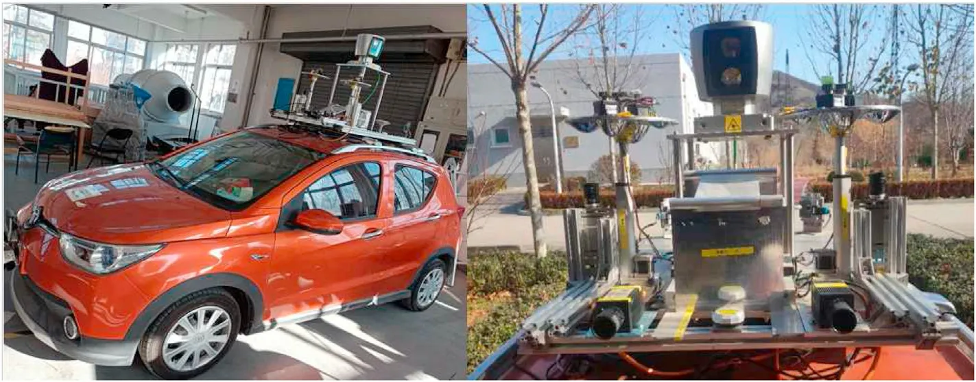
Fig. 5. UGV experimental vehicle.
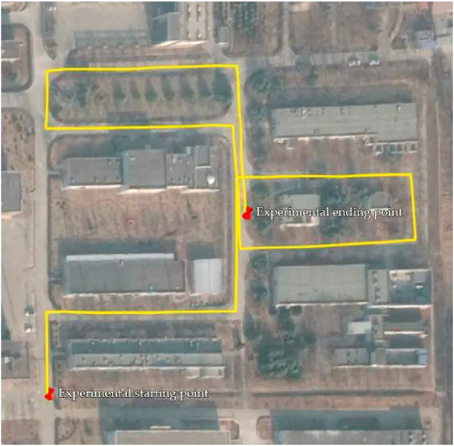
Fig. 6. The preset route of the experiment.
The experimental data of 5 consecutive records are shown in Fig. 7./oxts_gnss is the inertial navigation data, including various navigation information including latitude and longitude;/left/image/compressed and/right/image/compressed are Image data of binocular stereo vision system;/panoramic_camera/left/image_raw and panoramic_camera/right/image_raw are the image data of the binocular stereo panoramic vision system./velodyne_points are the point cloud data of LIDAR.
After data acquisition, the recorded data is played back offline,the image of the binocular stereo vision system runs the binocular DSO algorithm,and the trajectory diagram output by the algorithm is recorded. For the image of binocular stereo panoramic system,run the binocular DSO algorithm supported by the extended panoramic vision system model, and record the output trajectory diagram.
Using HDL-graph algorithm to process data of LIDAR and Integrated inertial navigation system. Considering the difficulty of processing the experimental data and the error of the output navigation data, a Ground Truth [41] track is formed by using five experimental tracks after algorithm optimization,as shown in Fig.8 and Fig. 9.
Perform coordinate conversion on the output Ground Truth trajectory, convert the trajectory value to latitude and longitude,save it as a csv file and import it into Google Earth, as shown in Fig. 10. It is basically consistent with the experimental preset roadmap,which proves that the Ground Truth trajectory is true and reliable.
Run the binocular DSO to process the experimental data of the ordinary binocular stereo vision system, and draw the five times track output by the algorithm and the track of ground truth(Fig.11 and Fig.12).
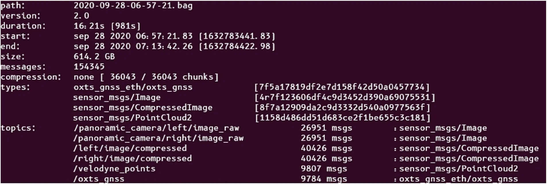
Fig. 7. Data of 5 consecutive experiments.
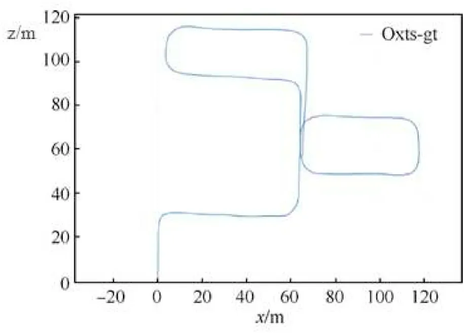
Fig. 8. Ground Truth trajectory diagram.

Fig. 9. Ground Truth XYZ direction trajectory diagram.
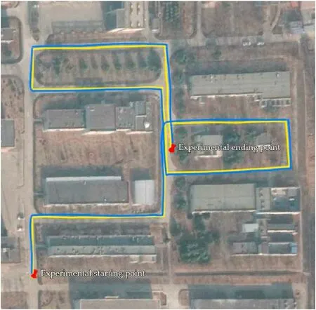
Fig.10. Ground Truth satellite map.
In Fig.11 and Fig. 12, oxts-gt is Ground Truth, which is represented by a gray dashed line. Stereo-10 and stereo-10a represent the first and second experiments with a speed of 10 km/h, and so on,stereo-15 is a speed of 15 km/h.For the binocular stereo vision system,a large rotation error is generated at the turn.In the lower speed test routes of 10 km/h and 15 km/h, a large rotation error occurs at the first turn, resulting in a deviation in the subsequent route, but the basic trajectory shape is consistent with Ground Truth, and the consistency of the three experiments is good. After the speed reached 25 km/h,because the turning speed was too fast,a large rotation error was generated at each turn. However, in the straight driving part, the overall trajectory did not deviate due to the too fast speed. When the speed is 30 km/h, the tracking is quickly lost due to the too fast speed, and the UGV's driving trajectory is also completely wrong.
3.2. Experimental results and analysis
Experiments show that for ordinary vision ordinary binocular vision, the highly dynamic scene of turning can easily cause the image difference between the upper and lower frames to be too large.As shown in Fig.13,the UGV is in the turning process,when it just enters the intersection,tree of the blue box moved to the center of the image,and disappeared when the UGV was about to leave the intersection, while the UGV moved a small translation distance during the turn. This kind of image sequence with excessive rotation changes has a great impact on DSO,will produce larger errors or even tracking loss.
Similarly, it can be seen from the trajectory diagram in the XYZ direction that only two experiments with lower speed are closer to Ground Truth among the five experiments. The errors in the third and fourth times are both large.The fifth time the tracking is lost in the middle, the positioning failure.
Run the binocular stereo panoramic DSO algorithm to process the binocular stereo panoramic image data, and draw the 5 experimental trajectories and Ground Truth trajectories obtained by the algorithm (Fig.14 and Fig.15):
The five solid lines in Fig. 14 are the trajectories of the UGV obtained by the five experimental algorithms,the dashed line is the Ground Truth trajectory,and the yellow and purple trajectories are the trajectories obtained by the visual mileage calculation method when the vehicle is traveling at 10 km/h. Among the five trajectories, the trajectory of the UGV is closest to the Ground Truth trajectory. Red, blue, and green are the trajectories when the vehicle is traveling at 15 km/h,25 km/h,and 30 km/h respectively.The red track of 15 km/h and the blue track of 25 km/h basically coincide,but it deviates more from Ground Truth than the 10 km/h trajectory at a lower speed. In addition, the 25 km/h trajectory produced data jitters due to excessive speed at one of the turns,resulting in a large deviation in the trajectory. In the experiment with a speed of 30 km/h,the trajectory has a large deviation in the right loop and a large deviation in the x direction, but the overall tracking of the map points is not lost. The calculation can be maintained in a relatively stable state. Compared with the fifth experiment of ordinary binocular vision, the binocular stereo panoramic vision system shows better performance.
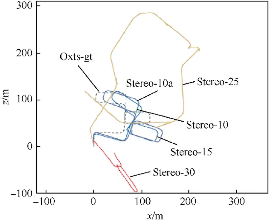
Fig.11. The first to fifth trajectory diagrams of the binocular stereo vision system.
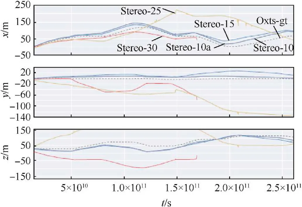
Fig.12. The 1st to 5th trajectory diagram of the binocular stereo camera-XYZ direction.
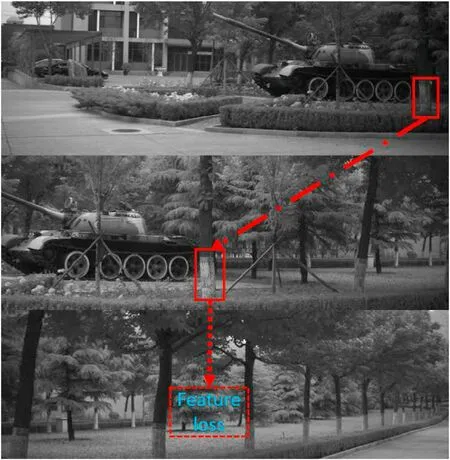
Fig.13. Normal camera image during turning.

Fig. 14. The 1st to 5th trajectory diagram of the binocular stereo panoramic vision system.
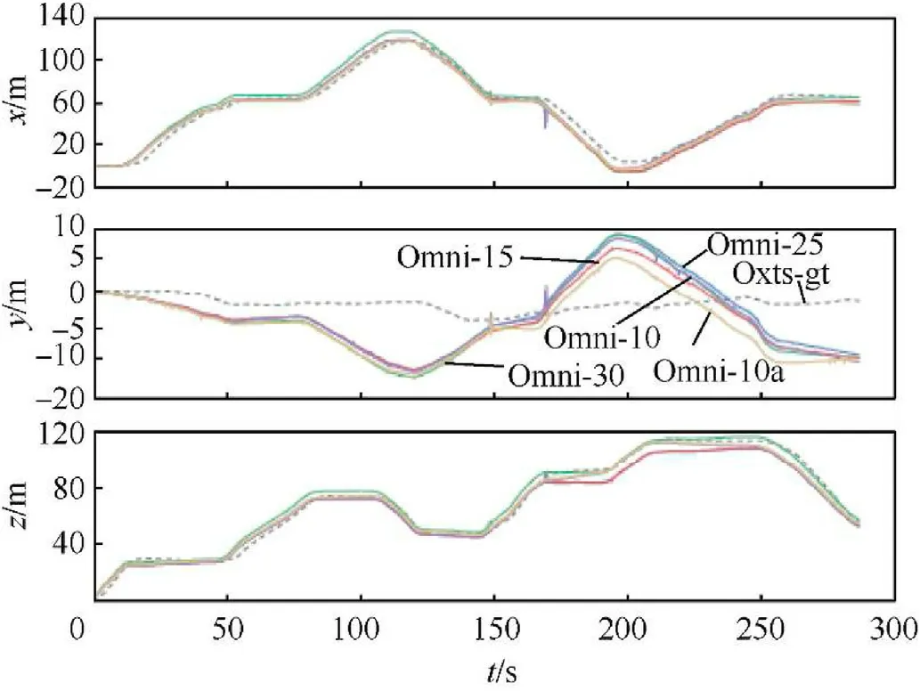
Fig. 15. The 1st to 5th trajectory diagram of the binocular stereo panoramic vision system-XYZ direction.
Obviously, after comparison with the binocular stereo vision system,it can be found that the experimental track of the binocular stereo panoramic vision system has greatly improved the accuracy of translation and rotation,especially for the quick turning problem that the binocular stereo camera cannot solve,the panoramic vision system does not exist, as shown in Fig. 16. The panoramic vision system can be observed most of the surrounding environment points during the turning of the UGV,so it can always track the map points in the image, and will not cause the tracking accuracy to decline or fail because the speed is too fast and the image information between frames changes too much.
The absolute error analysis of the trajectory of the binocular stereo vision system and the binocular stereo panoramic vision system is shown in Table 4 and Table 5.
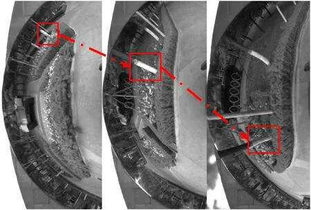
Fig.16. Binocular stereo panoramic vision system image during turning.
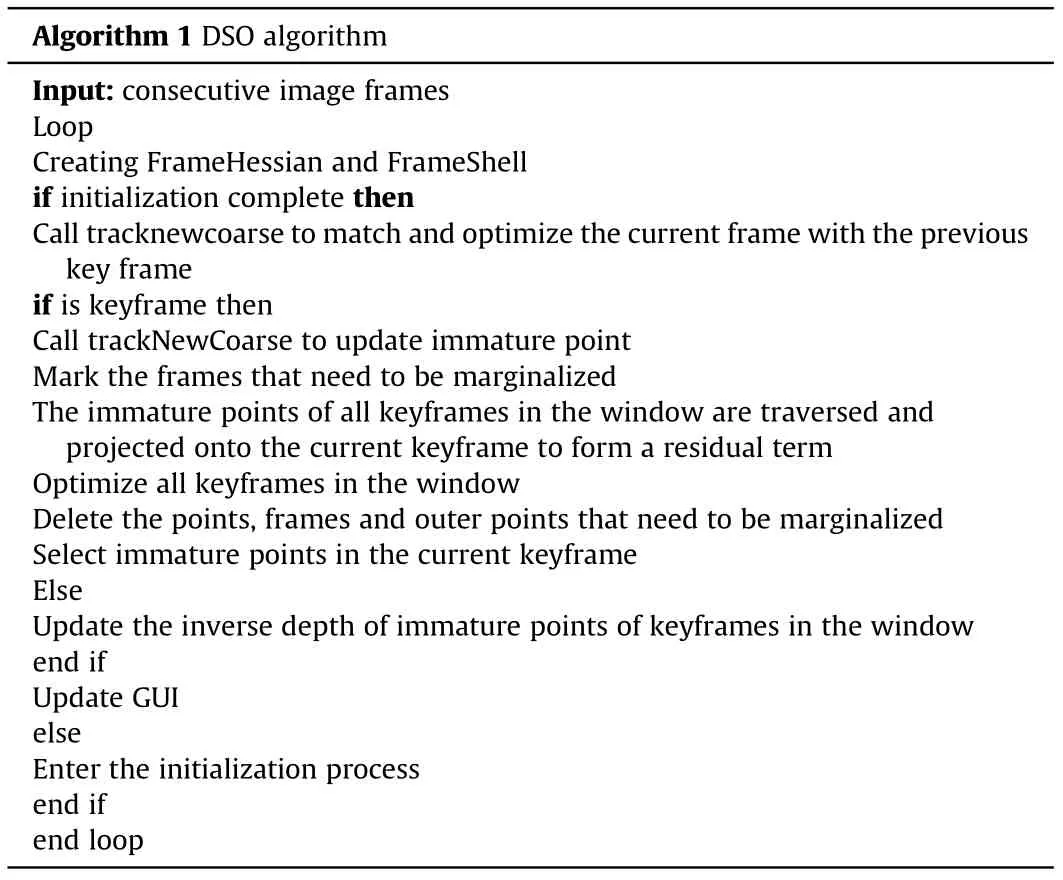
Table 2 Algorithm flow chart of monocular DSO.
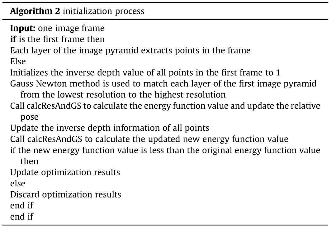
Table 3 Algorithm flow chart of monocular DSO.
Table 4 and Table 5 record the absolute errors between the Ground Truth and the trajectories of the five experiments of binocular stereo vision system and binocular stereo panoramic vision system. The maximum error of binocular stereo vision system varies greatly at different speeds, from about 52 to 238 m,because of the influence of speed. In the result of binocular stereo panoramic vision,the maximum error is controlled between 10 and 30 m in terms of average error, the average error of the binocular stereo vision system at any speed is greater than that of the binocular stereo panoramic vision system. the minimum error value is accidental,and the intersection with Ground Truth will also produce a small minimum error value, so it cannot be used as a basis for analysis.
The error data is analyzed in detail, and the root mean square error (RMSE), Sum of Squares due to Error (SSE), and Standard Deviation(STD)[42]of each experimental trajectory are calculated and analyzed from a statistical perspective.RMSE is the sum of the squares of the difference between each trajectory point and Ground Truth in the entire trajectory, and then take the average value and then extract the square. This data reflects the deviation between the data point and the true value.During the binocular stereo vision experiment, as the speed increases, the RMSE also increases, and the deviation between the generated trajectory and Ground Truth is getting larger and larger. Comparing the five experiments of binocular stereo panoramic vision system,the RMSE changes little with the increase of speed, and the value is also lower than the respective values of the binocular stereo vision system, indicating that binocular stereo panoramic vision can still maintain a relatively stable trajectory output when the speed increases.SSE is the sum of squares of errors, which is the sum of squares of errors between each trajectory point in the entire trajectory and Ground Truth.This value reflects the overall deviation of the experimental trajectory from Ground Truth. The value of the binocular stereo panoramic vision system on SSE is one to two orders of magnitude lower than that of the binocular stereo vision system. STD is the standard deviation, reflecting the degree of deviation of the data from the mean,and more reflecting the difference between its own mean.Compared with RMSE,STD is more stable in binocular stereo vision system, but it is very stable in binocular stereo panoramic vision system and its value is much smaller than that of binocular stereo vision system. It shows that regardless of the binocular stereo vision system or the binocular stereo panoramic vision system,although the degree of error is quite different,the stability of the data can still be guaranteed,indicating that the algorithm is relatively good in the smoothness of the trajectory output.
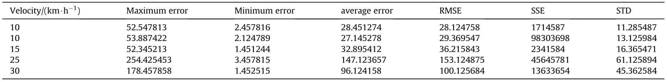
Table 4 The absolute error of the trajectory of the binocular stereo vision system.

Table 5 The absolute error of the trajectory of the binocular stereo panoramic vision system.
Based on the improved DSO algorithm, the binocular stereo vision system and the binocular stereo panoramic vision system were tested on actual roads.The test results show that for the same algorithm,the performance of the vision system with a large field of view angle is better than that of the narrow field of view.
4. Conclusions
This paper proposes a binocular stereo panoramic vision location algorithm based on extended DSO. The results show that the algorithm using extended DSO can effectively solve the resource consumption of high-resolution image feature extraction, and avoid the problem of feature point extraction difficulty caused by large-scale image distortion. The experimental results show that the binocular stereo panoramic vision system based on extended DSO algorithm has higher positioning accuracy and stronger robustness than ordinary binocular stereo vision system. To sum up,the binocular stereo panoramic vision system and the extended DSO positioning algorithm proposed in this paper have good application prospects,and explore a new way for the slam direction of unmanned panoramic vision.
This dissertation focuses on the research of panoramic vision system and visual odometer, analyzes and expands the existing DSO algorithm, so that it can adapt to the binocular stereo panoramic vision system. To verify the actual application effect of the binocular stereoscopic vision system in the perception of unmanned vehicle environment,this paper collects the experimental data under the same outdoor conditions by using the ordinary binocular stereo vision system and the binocular stereo panoramic vision system in the actual environment at the same time, use the extended version of the DSO algorithm to calculate the trajectory of the vehicle, and compare and analyze it with the Ground Truth trajectory obtained through the lidar and integrated navigation system. The results show that the binocular stereo panoramic vision system based on the extended DSO algorithm has higher positioning accuracy and stronger robustness than the ordinary binocular stereo vision system. In summary, the positioning algorithm based on the extended DSO binocular panoramic vision system proposed in this paper has a good application prospect and explores a new way for the direction of unmanned vehicle panoramic vision slam.
5. Future work and challenges
Future work will consider the shortcomings of no loop detection,map reuse,relocation after loss,and slow initialization of DSO.In some complex and multi-featured scenes or artificially place some highly recognizable artificial marker scenes for experiments to achieve better experimental results.
The authors declare that they have no known competing financial interests or personal relationships that could have appeared to influence the work reported in this paper.
The authors would like to thank Xu Chen for assistance with SLAM algorithm. The authors would like to acknowledge the Project of National Natural Science Foundation of China (Grant No.61773059) and the Project of National Defense Technology Foundation Program of China(Grant No.20230028)to provide fund for conducting experiments.

- Defence Technology的其它文章
- Dynamics of luffing motion of a hydraulically driven shell manipulator with revolute clearance joints
- Blast performance of layered charges enveloped by aluminum powder/rubber composites in confined spaces
- Chemical design and characterization of cellulosic derivatives containing high-nitrogen functional groups: Towards the next generation of energetic biopolymers
- Applicability of unique scarf joint configuration in friction stir welding of AA6061-T6: Analysis of torque, force, microstructure and mechanical properties
- Multi-area detection sensitivity calculation model and detection blind areas influence analysis of photoelectric detection target
- Accurate analysis of limiting human dose of non-lethal laser weapons