
In fluence of metal/composite interface on the damage behavior and energy absorption mechanisms of FMLs against projectile impact
2022-03-29 07:08:22SananKhanAnkushSharma
Defence Technology 2022年3期
Sanan H.Khan ,Ankush P.Sharma
a Department of Mechanical Engineering,Aligarh Muslim University(AMU),Aligarh,202002,India
b Department of Aerospace Engineering,Indian Institute of Technology Madras,Chennai,600036,India
ABSTRACT This paper focuses on the interface failure in metal/GFRP laminates on account of the high-velocity impact phenomenon by a hemispherical projectile.The study considers three laminates in which the failure inside the 8-layer 0/90 GFRP laminate is compared with the other two laminates that include metal layers in their layup con figuration.The metal layers were placed on the top and bottom on one type of laminates while in the other additional metal layers are placed symmetrically inside the layup as well.They were subjected to high-velocity impact by a hemispherical projectile at different energy levels and the idea is not to perforate the laminate con figuration instead to account for the damage incurred in these laminates and the role of metal layers in providing resistance to damage within these laminates.The study utilizes experimental findings and proposes a rate-dependent Finite Element(FE)model consisting of the Hashin-Puck failure scheme for composite and the Johnson-Cook damage model for metal layers.The results of the model satisfactorily agree with their experimental counterparts and provide valuable insight into the damage resistance inside the laminates.It has been observed that the 8-layer GFRP laminate was good in terms of elastic recovery and prevention of propagation of damage inside the laminates only,till the impact energy was lower.For higher impact energy,they show poor damage resistance as the fiber failure is triggered in them.However,laminates with metal layers are shown to protect the laminate by dissipating energy in the delamination of metal/GFRP interface,shear failure of the metal layer,and on account of metal plasticity.The study further shows that the throughthickness compressive stresses were responsible for the failure of laminates and also triggering the delamination in them.A damage energy study was performed to investigate the amount of energy dissipating in various failure modes like delamination,matrix cracking,fiber failure,etc.
1.Introduction
As technology is advancing,the role of hybrid materials in today’s world is taking more attention from researchers.One such material is Fiber Metal Laminate(FML).It’s a hybrid material manufactured by combining composite laminates and metal alloy in some proportion to obtain the characteristics of both constituent materials.The composite and metal alloy are not combined at the molecular level but the laminae of both materials are stacked together in some speci fied con figuration to achieve the desired purpose.This con figuration offers special advantages like superior impact energy absorption[1],good out of plane impact resistance[2],and low fabrication cost[3]compared to their constituents.They also offer other advantages due to their constituents like lightweight,excellent corrosion,and fatigue resistance,to name a few[4].This lead to a signi ficant development in aerospace[5],naval[6,7],and automobile industries[8]in virtue of the superior properties of FMLs.The manufacturing method of FMLs is close to the composite laminates however the importance of the type of composite and metal layer needs to be discussed.The composite laminates may consist of glass fiber,aramid fiber,or carbon fiber while the metal layer may be of aluminum,titanium,or magnesium alloys[9].The most studied combination is glass fiber along with aluminum layers also known as GLARE(Glass Laminate Aluminium Reinforced Epoxy)because it offers superior properties at low cost and hence is more favorable for practical applications[10-13].
In the past GLARE has been exposed to distinct loading conditions like tensile[11,15-18]and low-velocity impact loading[10,19-23]scenarios.Among them,some researchers have used Classical Laminated Plate Theory[11,24]to predict the stress-strain response of FMLs while others have used numerical simulation tools like the Finite Element Method(FEM)to predict the behavior of GLARE[14]and comparing them with their experimental counterparts.The low-velocity impact failure of GLARE laminates is frequently encountered during the take-off and landing of aircraft when the lower fuselage of aircraft,which is made up of GLARE,experienced the impact of runway debris and hailstones[25].Though the velocity of this debris is small(~20-30 m/s)but they may cause a localized shear failure because of the nucleation of a crack occurring due to such type of fatigue loading[26-28].Further researchers have also studied the propagation of these critical cracks inside the laminates leading to prominent delamination within the metal/composite layers[29-31].Moreover,the Digital image correlation(DIC)technique is used by many researchers to study the behavior of laminates,experimentally.This technique is used to measure the deformation and velocity of the back surface of the specimen.To facilitate this,the back surface of the specimen is applied with a random intensity pattern using paint.There are different ways to achieve the specimen with a speckle pattern such as pressurized spray paint,toothbrushes,and manual random dots using special OHP markers.Some latest studies[32-34,104,105]reports DIC with its more information and application.
In the past few years,it has been observed that the application of FMLs has become widespread to all forms of structures be it a critical or non-critical load carrying component.The car hood(bonnet),the submerged hull of a ship,armor plates for military people,etc.are primary load-carrying components but are mostly subjected to sudden intense dynamic loads.The examples may vary from bird strikes in the aviation industry to the collision of vehicles in the automobile industry all leading to a catastrophic failure occurring due to high-velocity impact loads.Hence,it’s important to observe this behavior well in advance for FMLs so that appropriate troubleshooting can be performed on account of failure.Some researchers have observed the behavior of FMLs based on impactor mass,size,and shape and studied their effect on the ballistic limit[21,35].The ballistic limit is the term coined for the minimum velocity of mass indenter before which it perforates the given material or target completely.The FMLs are also studied based on their layup con figuration and total laminate thickness[36-39]during ballistic impact.Since the high-velocity impact event is a transient phenomenon and all of its aspects are dif ficult to monitor experimentally,especially the damage initiation and its propagation within the laminates,the FE method is an attractive,ef ficient,and reliable tool.Some researchers have modeled the FMLs at high-velocity impact loading conditions based on fabric type,indenter used or layup con figuration,etc.[40-44].This also includes some of the latest studies published recently[45-47]which mostly investigates the failure in FMLs during projectile perforation.However,the authors in this study would not like to perforate FMLs[48]instead,want to penetrate it to some extent,and investigate the intralayer failure,interface failure,and their propagation within the laminates during transient loading conditions like a projectile impact.These loading and failure conditions are closer to the practical scenarios given above.
In this study,an attempt is made to investigate the damage resistance of FMLs on account of the high strain rate impact by a hemispherical projectile.In no way this study investigates the perforation of the target,instead,the damage analysis of the critical regions within the laminates is observed by damaging the FML by moving projectile,based on performance parameters using experimental findings earlier[38]followed by the detailed FE analysis.Further,this study enlarges the horizon of the metal/composite interface and the effect it produces on the overall damage resistance of the particular laminate layup.The study will be useful for design engineers,after which they will be able to choose the ef ficient tailor-made laminate con figuration according to their speci fic requirements.
2.Experimental setup and procedure
The experiments were performed using the nitrogen gas gun driven indigenous setup designed and assembled in the laboratory as shown in Fig.1.The setup consists of a nitrogen cylinder,barrel,solenoid valve,LEDs,Photodiodes,safety chamber,power supply,digital oscilloscope,and Photron SA 1.1 camera modules.FML specimens of size 100×100 mmwere sandwiched between the supporting plates of size 200×200 mmwith an inside effective opening of 70 mm diameter for exposure to the high-speeding projectile(see Fig.1c).The use of supporting plates effectively helps to curtail the specimen symmetrically and makes laminate failure independent of the boundary condition.The impact velocity of the projectile was measured by using two infrared LED sensors along with photodiodes placed at the end of the barrel just before impact.Each pair is placed linearly at a known distance apart and the time instant of moving projectile is recorded by the oscilloscope when it obstructs the sensor-diode circuit.Although the specimen fixture is installed on the same housing,however,to recover the projectile safely and also to observe the out of plane deformation of samples,a protective enclosure is made with two acrylic windows on the rear side.The specimen is installed on the same housing and once the projectile perforates the specimen,it is recovered in the protective enclosure.This is to ensure that the optics like the two cameras and their connection is protected from the danger of moving projectile.The two cameras that were placed for stereo imaging,notice the behavior of the rear side of the specimen to measure the displacement fields.The acrylic windows mounted on the protective enclosure were placed at a certain angle(152.5in experiments)as demanded by the requirement of the stereo imaging(see Fig.1d).The two-camera setup is also placed along the same orientation axis as explained by the line diagram in Fig.2 The displacement fields were measured with the help of a DIC technique.For this,a random intensity pattern(i.e.,paint)was sprayed on the back surface of the specimen[14].As the specimen deforms during the impact event,the random dots move to different positions in subsequent camera images.The correlation is done for the images obtained from both the cameras by using Vic-3D?software(Correlated Solutions Ltd.)and the displacement fields were measured.For more details about the camera setup,the reader is advised to refer to Ref.[49].Further,it is to be noted that the displacement fields obtained by DIC represent the deformation of the rear aluminum layer only and in no way can attribute to the whole specimen.This is because as the delamination initiates between the layers of the damage pattern,its evolution changes for both aluminum and composite plies.Hence FE analysis becomes an important tool to look into these aspects during the impact event.
The projectile used is made up of maraging steel(hardened)and has a mass of 16.7 g with a total length of 19 mm and a diameter of 12.47 mm.Two types of FMLs,i.e.2/1-0.6([A6/0/90/90/0/A6])and 4/3-0.3([A3/0/A3/90])(where A is abbreviated for the aluminum layer)were designed with the total laminate thickness of 3.55 mm and 3.70 mm respectively.To compare the effect of the metal interface delamination on the overall behavior of the laminate,8-layer composite laminate[0/90/90/0/0/90/90/0](having a thickness of 3.85 mm)was also prepared.The preparation of these laminates was done by hand layup method and they consist of Eglass fibers as reinforcement and Epoxy LY556 as resin with aluminum alloy 2024-T3 sheets.For details on the preparation of these FMLs,the reader is advised to refer to the authors’previous article[14].
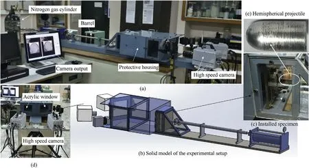
Fig.1.Experimental setup.

Fig.2.Line diagram for 3D camera Set-up.
3.Constitutive material modeling
In this section,constitutive relations that mechanically de fine the behavior of the material during FE analysis are presented.
3.1.Failure model for aluminum
The behavior of the aluminum 2024-T3 alloy was predicted using the well-known Johnson-Cook(J-C)failure initiation and evolution model[50].The failure initiation model includes the effect of strain hardening experienced by material in the plasticity regime accompanied by effects of strain rate.Due to the transient conditions experienced during the impact event,the effect of strain rate becomes important.The flow stress of the material is expressed as


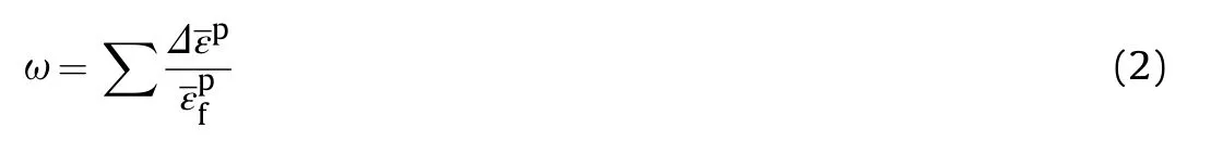


whereσis the stress triaxiality parameter and D,DDand Dare model parameters.These parameters are determined from experiments on notched and axisymmetric specimens at different strain rates.Some latest studies discuss these aspects in detail[55-57].The material properties used are summarized in Table 1.
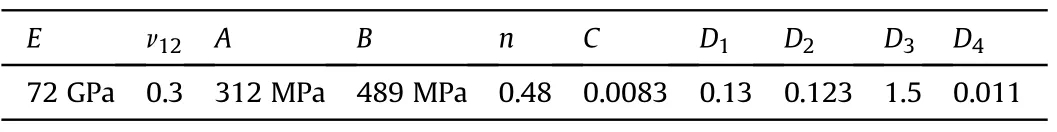
Table 1 Material properties of aluminum 2024-T3 used in this study.
3.2.Failure model for composite
Hashin failure criteria[58]is the most common criteria to model the behavior of composite laminates.It’s a mode-based criterion,that de fines the composite failure modes separately into four failure indices.These failure indices vary from zero to one.The important features of criteria are that the failure modes are independent of each other and include the provision for further adding the effect of certain stress components to the particular mode.However,some researchers[59-61]proposes the modi fications to Hashin matrix compression mode on account of in-plane shear,which reduces the compressive strength of ply.The puck action plane concept[61]is a popular way in which,matrix compression failure index is evaluated by the stress components on the fracture plane,which is usually oriented at 53±2for pure transverse compression.Thus,the scheme takes into account the effect of matrix shear strength in the failure index.Further,it also includes the effect of internal material friction by incorporating two coef ficientsμandμ.The combined model is said as Hashin-Puck failure criteria in this study and is de fined as
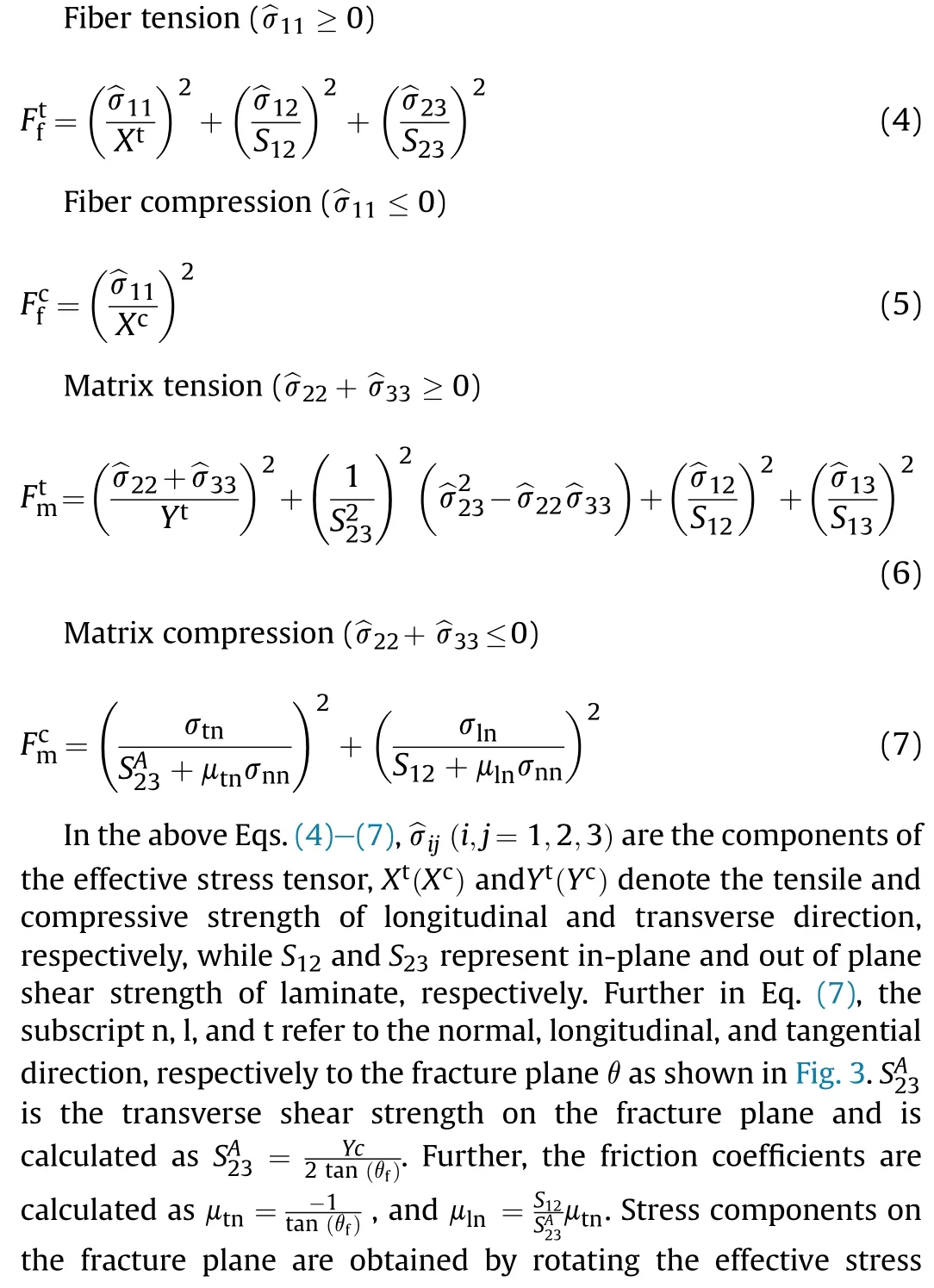

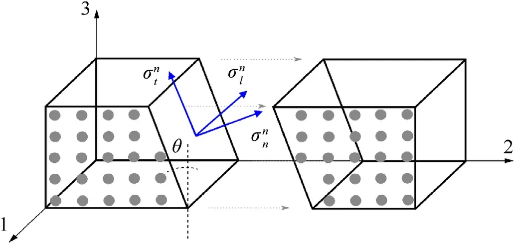
Fig.3.Stress components on the fracture plane[73].


Since many studies[68,69]have shown that strain rate affects the modulus,strength,and toughness of glass fiber-based laminates hence it is important to elevate their strength during high strain rate phenomena like impact.Yen[70]has proposed simple logarithmic rate-dependent functions(inspired by the Johnson-Cook model)to elevate the strength of laminate during dynamic loading as
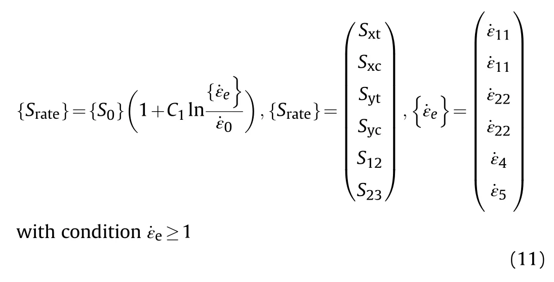
here Cis the strain rate constant,and{S}are the available strength values of{S}at the reference strain rate˙ε(t)=1/sec.The rate sensitivity parameters are different for each fiber(0.177)and matrix(0.2)and are adapted from earlier studies[71,72].All material properties of the E-glass/Epoxy composite have been summarized in Table 2 for the reader’s reference[106].
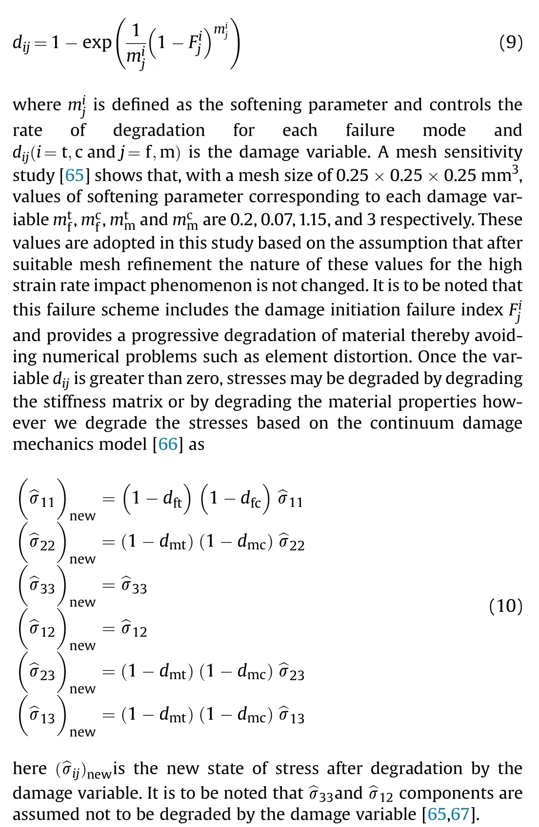
Finally,material constitutive laws including damage initiation,damage evolution,stress degradation scheme along with strain rate enhancement function are coded in FORTRAN and are implemented in Abaqus commercial finite element code via user subroutine VUMAT.It is to be noted that the element deletion is commenced once the damage variable dreaches close to unity(~0.997 used to avoid element distortion).As tensile failure occurs at the strength of a structure,which is along the fiber direction,hence dis chosen for element deletion scheme.A failure scheme of a composite laminate is shown in Fig.4 with the help of a schematic algorithm.As the displacement fields are produced as a result of applied boundary conditions,through which strains increments are generated and supplied to the subroutine loop at each increment.Using constitutive relations,stress increments are calculated and stored as an array in^σeach increment.These stresses were used to check the failure initiation in Eqs.(4)-(7).If any of the failure indexes reaches one,the corresponding damage variable dstarts initiating using Eq.(9).These variables degrade the updated stresses^σusing Eq.(10).It is to be noted that during simulation if the strain rate increases a particular threshold(set as 1000/s for composite laminates used in this study),the strength properties are elevated using Eq.(11)on account of a strain rate effect.
3.3.Interface delamination
The interface delamination between different layers of the laminate is initiated through cohesive surface interaction methodology.Under this,a simple traction displacement relationship is followed by the common node of the interface.When delamination initiates,the common node deforms and finally fails.This node failure is visualized as a connection break between the two layers which indicates delamination.The traction separation law^t=Kδholds the two surfaces together by utilizing a large penalty stiffness K.The value for this stiffness is suggested by some researchers[74,75]however Turon et al.[76]in their famous paper have shown that it is a function of matrix modulus and thickness of the adjacent interface layer.The interface failure of the two surfaces is decided through quadratic stress criteria,where traction in each direction is compared with their respectable user-de fined allowable(s),and equated to unity.Once the criteria are ful filled,contact point tractions are degraded using degradation law based on fracture energy.The degradation further happens based on three modes of fracture mechanics and interaction within these modes(mode mixity).For understanding the application of the above laws the reader may refer to the authors’article[77]and for detailed reading[78]can be followed.The material properties of the cohesive interface used in this study are listed in Table 3.

Table 2 Material properties of E-glass/Epoxy composite.

Table 3 Material properties of the cohesive interface[67].
4.Finite element procedure
A plate-projectile 3D pair model is created in the Abaqus part module.Laminates were created as deformable with local material orientation assigned to each layer.In these local orientations,0and 90layer may be assigned as per layup con figuration.Fig.5 shows a typical FE model of 4/3-03 laminate.It is to be noted that as the laminates were symmetric so the delamination nucleating within their interface will also be symmetric.Hence only onefourth of the model is suf ficient to analyze the laminates’behavior.The laminate has meshed with C3D8R solid continuum element with finer size elements i.e. element size of 0.2×0.2×0.2 mmat the impact zone while coarse size elements i.e.element size of 0.5×0.5×0.5 mmon the rest part of the layer.Two elements were used in the thickness of each layer so that results become mesh independent[79-81].Further the boundary of the laminate was made fixed using the encastre boundary condition available in the code[82].An initial velocity was assigned to the projectile while keeping the projectile a little away from the laminate to notice its first indentation.The projectile was made rigid with mass and inertia assigned at its reference point(R.P).A friction-based general contact constraint with cohesive behavior was assigned between the laminates however a hard contact was issued for the indenter and top layer of laminate.The hard contact is necessary as it avoids the unnatural penetration of indenter into laminates.During the deformation of laminates,element deformation is a common problem that leads to smaller stable time increment(Δt)and higher CPU time or may perhaps abort the solution.Hence to avoid that,mass scaling is used for certain elements that may behave abnormally during the progress of the solution.These elements were identi fied by verifying the mesh based on a suitable stable time increment.In mass scaling,some additional mass is provided to such elements so that the overall time increment is not compromised.However,the addition of mass should be small and should not change the physics of the problem.Studies[30,83]suggest that it should be less than 2%of the internal energy of the system.
5.Results and discussion
5.1.De flection/velocity variation
To analyze the damage resistance of the laminates its de flection during the impact event is an important parameter.The de flection may be maximum or permanent in the laminates attained during the impact event.The maximum de flection here indicates the ability of the laminates to undergo the highest elastoplastic deformation during the impact event,while the permanent de flection implies the ability of the laminate con figuration to perform elastic recovery ef ficiently(during the unloading phase of the impactor).The elastic recovery here indicates the ability of the laminates to spring back to their original con figuration as the projectile unloads.It is to be noted here that the de flection of the rear face of laminate(from the center)is observed in the experiment via DIC by choosing the central node point while calling it a displacement field variable in FE simulations.Fig.6 shows the de flection and velocity variation of three laminate con figurations observed during experiments and FE simulation at 30 J of impact energy level along with the DIC maps.This lower impact energy level provides suitability when distinguishing between three laminates.However,for higher impact energy,the deformation and damage are more severe and differentiation between laminates becomes dif ficult.It is seen that FE simulations successfully capture the behavior occurring in experiments for all three laminates in terms of the slope of a curve and maximum de flection.Some minor discrepancy occurs with the initial start of the time increment which could be attributed to the delay in capturing the event by the camera(i.e.low frame rate)which is 40 us.The elastic recovery of the monolithic C-8L laminates was the best(or permanent deformation is least),followed by 2/1-0.6 laminates as seen from Fig.6a and b respectively.The 4/3-0.3 laminates show poor elastic recovery post-impact events in both experiments and FE analysis.This is because it contains metal layers sandwiched inside the[0/90]laminate con figuration.During the deformation,the outer metal layer(non-impact face)is free to deform in tension while the inner metal layers are constrained between the brittle composite[0/90]layers and hence shows 12%lesser deformation as noticed from Fig.6c and also by some other studies[30,84,85].
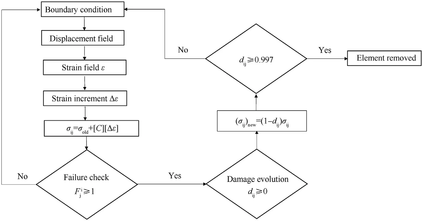
Fig.4.The algorithm followed in VUMAT.
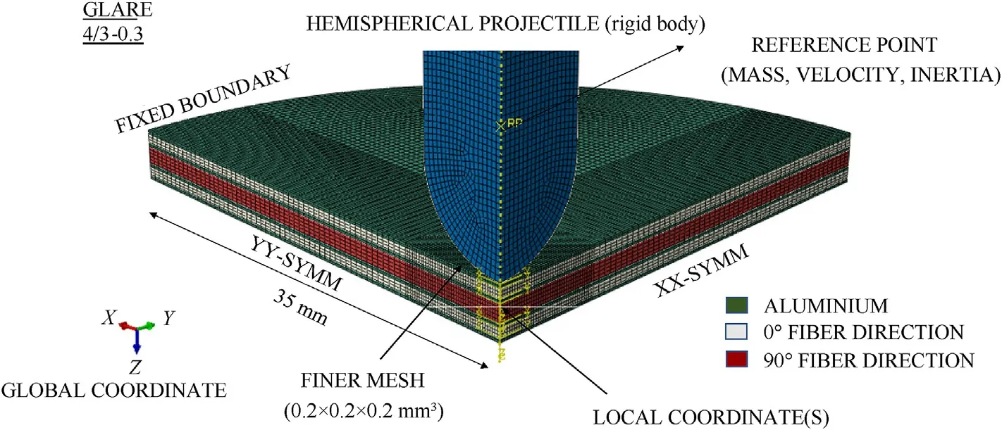
Fig.5.Finite element model.
The rear face deformation data is available from both experiments and FE simulations in Table 4 for all energy levels.All laminates show a consistent increase in deformation for 30 J,45 J,60 J,75 J,and 90 J impact energy levels.For higher energy levels the deformation is more severe and perforation or metal shear failure is observed within both 2/1-0.6 and 4/3-0.3 laminates at 90 J energy level in the outer metal layer.It is important to note here that the failure of these metal laminates is marked by the failure of the central point of the outer layer and in no way can be attributed to the whole laminate.Further,it is to be seen that no such failure of the laminates was noticed in the composite laminates and FE analysis competitively predicts the deformation values close to their experimental counterparts.This suggests that the material model proposed here satisfactorily predicts the deformation or failure occurring in laminates even at high energy levels or high strain rates.Further,the velocity variation of the rear metal laminate is also shown in these graphs.The velocity history is obtained by differentiating the de flection history in both experiments and FE simulations.It was noticed that FE simulations overpredicted the peak velocity values and there was a difference in the slope too.These differences occur due to differentiation carried out at low frame data(in experiments at 40 us)compared to higher frame data(FE simulation at 10 us).Now,as the projectile hits the target the kinetic energy is transferred to the laminates and the central material point of the rear plate attains the highest velocity at this forcing frequency[86]followed by slower elastic recovery at its natural frequency[87]during the loading part as seen in Fig.6.This slower recovery process is most evident in the 4/3-0.3 laminate case in which the inner metal layers further delays the recovery process as shown in Fig.6c.

Table 4 Maximum rear face deformation data.
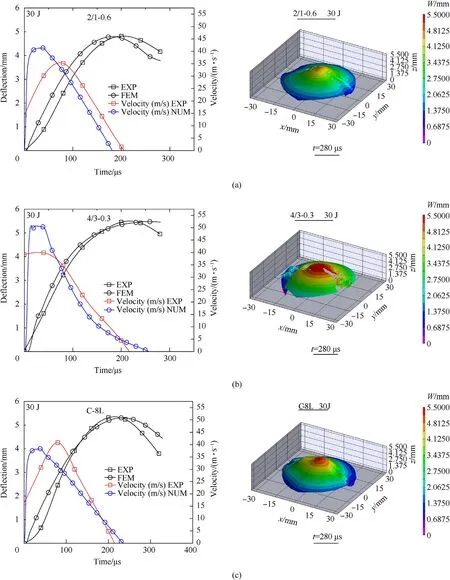
Fig.6.De flection and velocity variation of the rear face of laminates including DIC maps.
5.2.Contact time
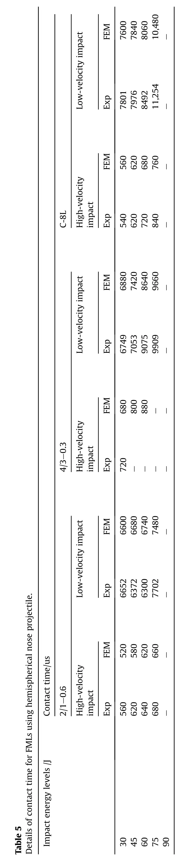
The contact time is de fined as the amount of time taken by the projectile to remain in contact with the target during the complete impact event.This includes the time of the projectile striking the target and unloading time taken by the projectile as a result of the elastic recovery of the specimen.Table 5 compares the contact time of three types of laminates for both high and low-velocity impact phenomenon at the same impact energy.
For the case of high-velocity impact,C-8L and 2/1-0.6 laminates show an increase in their contact time as the impact energy increases.This is because for higher energy levels higher damage is done by the projectile to the target and the elastic recovery is delayed due to which projectile takes more time to rebound.The composite laminate C-8L although shows good elastic recovery initially as discussed in the previous section,but as the impact energy increases the failure propagates inside the laminate and hence the stiffness of the laminate is reduced(due to excessive fiber failure).For 2/1-0.6 laminate during the impact,the top metal layer first deforms elastic-plastically and pushes the four layers[0/90]composite stack.However,for 4/3-0.3 laminate,the composite stack consists of two-layer[0/90]laminate separated by the middle metal layer(s).These additional metal layers absorb more kinetic energy of the projectile than 2/1-0.6 laminate.Table 5 shows that for 4/3-0.3 laminates the projectile has not able to rebound back for higher energy levels and hence the contact time is not recorded for it.
Further,the effect of loading rate is also shown in Table 5 by comparing the contact time(s)during low-velocity impact(see authors previous articles[30,88]).It was seen that approx.A ten to fourteen times increase in the contact time is noticed in all three laminates at the same energy levels in the low-velocity impact phenomenon.However,the contact time taken by C-8L laminate is highest for all the energy levels in low-velocity impact compared to the other two laminate(s).This suggests that the effect of strain rate is substantial for all laminates consisting of[0/90]composite layup and it’s important to incorporate this rate effect in the constitutive equations of the material model for the correct prediction of the behavior of laminates.
5.3.Through thickness stress variation
The process of impact by the projectile is usually a localized deformation phenomenon driven by a high magnitude of thickness stresses.These stresses vary along with the thickness of the target and push the material opposite to the direction of impact.They are responsible for triggering various failure modes in composite and metal layers accompanied by interface delamination and are majorly responsible for the structural failure of the material as a whole.It is to be noted here that the stresses are usually relaxed after the initiation of failure inside the laminate as the energy coming from stresses is dissipated or released in failure crack formation.Hence it is important to assure that while comparing the stresses from different laminates a particular time instant must be chosen at which none would have failed.The plot of stresses Sis created for three laminates considered in this study at a particular time instant before failure at 30 J energy level and is shown in Fig.7.The plot varies from the point of impact to each element along with the thickness of the laminate on various metal/composite layers.It is seen that the stress is maximum compressive for all laminates at the point of impact and it becomes more and more tensile(layerwise)towards the non-impact face of laminates.Further,the maximum compressive stress Sis depicted by 4/3-0.3 laminate followed by 30%lesser stress magnitude of 2/1-0.6 laminate.Moreover,it is also noted that these two laminates show compressive stress reduction when stress moves from the metal layer to the composite layer or vice versa.However,no such variation is seen in the C-8L laminate which does not have a metal layer inside its con figuration.The stress Sremains almost the same inside the C-8L laminate layers and after halfway,along with the thickness,the stress started becoming tensile but rather slowly.Hence this stress variation must have been occurring due to the difference in the stiffness of the metal/composite layers.
5.4.Delamination at the interface
In this section,the interface delamination variable(CSDMG)is evolved at each interface of the three laminates considered in this study.The interfaces are also correspondingly compared with the low-velocity impact study performed earlier by the authors[30].The interface delamination usually propagates along the fiber direction and is governed by the interlaminar shear stress S[89,90].The variation of interlaminar shear stress is plotted for one of the laminate layers along the fiber direction in Fig.8d.It is seen that as tensile shear stress(already delamination started)is becoming compressive and as the delamination propagates further along the path stress becomes tensile and thus creating further delamination.It is to be noted that the interlaminar shear stress Sis driven by the through-thickness compressive stresses Sand this traction component is used in the quadratic stress criteria to evaluate the failure between the two nodes,as discussed in section 3.3 above and comprehensively in some studies elsewhere[91-93].
The delamination pro file seems to be propagating towards the boundary in the subsequent layers beneath the impact.Fig.8 compares the delamination in each layer of the three laminates from the low velocity and high-velocity impact phenomenon at 30 J of impact energy.The delamination pro files in the subsequent layers of all three laminates are increasing in shape and size for high-velocity impact.A closer look at the pro files indicates that the pro file is enlarging in high-velocity impact as if the lowvelocity impact is performed at a higher energy level.This perhaps is due to the rate effect experienced by the laminate layers during the high-velocity impact.Although during the interface modeling no strain rate effect is considered in the constitutive equations,the inclusion of rate effect by Eq.(1)for metal layers in the J-C model and logarithmic Eq.(11)for composite layers has clearly shown an indirect effect on the delamination pro files.This is because delamination is driven by the Sand Scomponents of stresses as discussed above.The rate effect with the Scomponent is seen very clearly in Fig.8d where the lower magnitude of these stresses has produced a smaller delamination pro file in low-velocity impact cases.These modalities will be dif ficult to capture during the experiments.It is to be noted that in Fig.8d the Scomponent is traced on Al/0 interface(by removing the metal layer)along the fiber direction,for both low velocity and high-velocity impact case at a particular time instant.
Further,the delamination pro files for the top and bottom interface are compared in Fig.9 for C-8L laminate using an experimental and translucent image from numerical analysis.Although the glass fibers used in the experiments are translucent as well,as the number of layers is higher hence the delamination pro files are merged and the view has deteriorated.Only top and bottom interfaces are compared experimentally and it was noticed that the pro file matches satisfactorily excluding some imperfections.The top interface in both cases shows a typical rectangular size peanut shape[94,95]expanding along the fiber direction however it is the bottom face that experiences greater delamination in the high-velocity impact case.It is to be noted that the other two laminates which include top and bottom metal layers are not shown because in the experiment the delamination pro files are hidden behind these layers.
Low-velocityimpact FEM 7600 7840 8060 10,480-Exp 11,254-7801 680 FEM 8492 760 7976 620-impact High-velocity C-8L Exp 540 620 560 720 840-Low-velocityimpact FEM 6880 7420 8640 9660-Exp 9075 7053 9909-880--FEM 680 4/3-0.3 6749 impact Exp High-velocity 800 720 FEM 6600 6680-6740-7480--Low-velocityimpact-DetailsofcontacttimeforFMLsusinghemisphericalnoseprojectile.Exp 6652 6372 6300 7702-Contacttime/us 520 580 620 FEM 660-2/1-0.6 High-velocity impact Exp 560 620 640 680 Table5 Impactenergylevels/J 30 45 60 75 90-
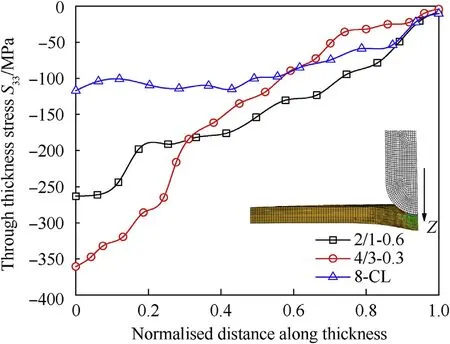
Fig.7.Through thickness stress variation inside the laminates.
5.5.Failure modes
The metal/composite laminates exhibit various failure modes like metal shear cracking,interface delamination,matrix tensile failure,etc.during the impact event and these are discussed in this section.The cross-sectioned samples across the fiber direction for 2/1-0.6 laminates are shown in Fig.10 for low velocity and high-velocity impact both at 60 J energy.The type of boundary condition and symmetric laminate con figuration used in this study allows the experiment and numerical failed specimens to be compared side by side.It is observed that the low-velocity impact at 60 J energy level creates a shear failure crack on the top metal laminate(labeled as A in Fig.10a and c)while no such failure is seen for the case of a high-velocity impact.In fact,from the numerical prediction in Fig.10d,it is noticed that the crack is about to initiate on the impact face while no sign is shown on the non-impact face(JCCRT variable is below 0.5).Further composite/metal layer delamination is seen in both the cases marked as C in Fig.10a and b.It is to be noted that the experiment samples are relaxed postimpact events while the simulation is stopped after the impactor lost contact during unloading.Hence in numerical prediction,the laminate is seen to be compressed compare to the experiment sample.
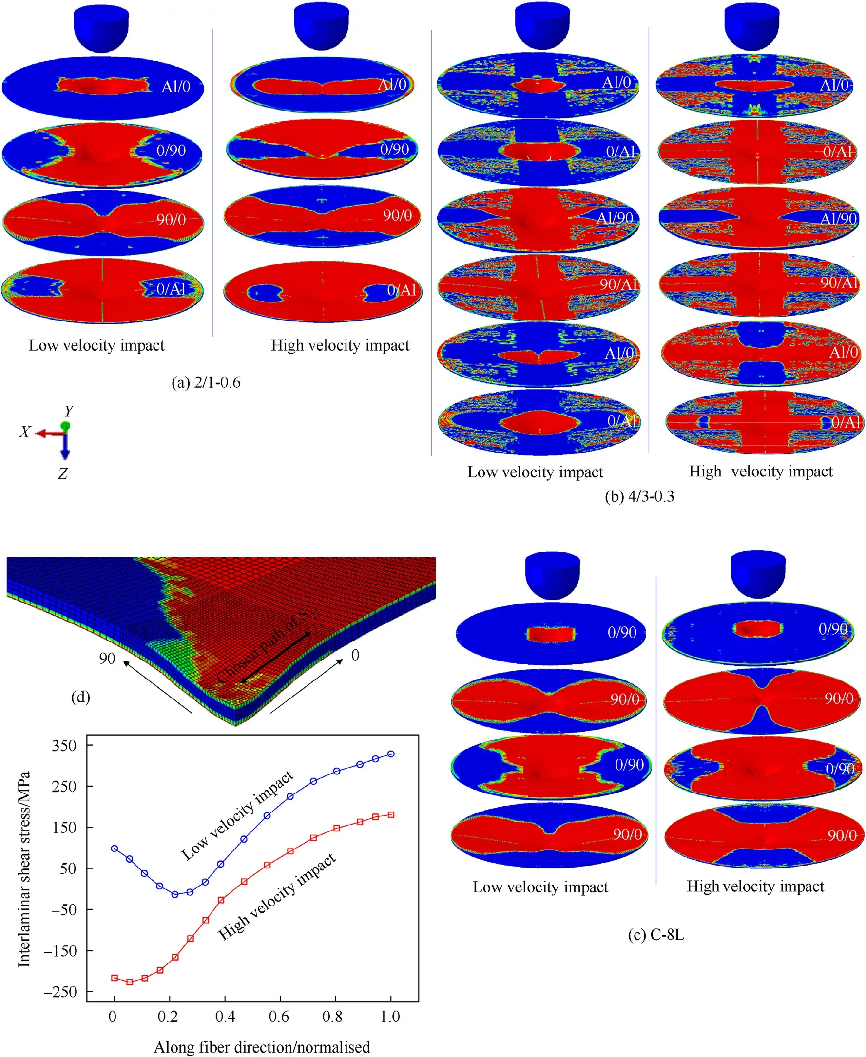
Fig.8.Interface delamination in each layer at high and low-velocity impact.
Fig.11 describes the post-impact images of 4/3-0.3 laminate where an additional metal layer is placed between 0/90 layers symmetrically inside the con figuration(compared to 2/1-0.6 laminate).It is observed that the damage is more severe in this case.In low-velocity impact,both impact and non-impact face experience metal shear failure where on impact face a circular fragmented material is removed while a shear cut along the fiber direction is noticed on the non-impact face as seen in Fig.11a and c.However,in high-velocity impact,shear failure of impact face metal layer does occur with no sign of crack on the non-impact face as noticed from Fig.11b and d.A dent,depression,and failure craters[96]are noticed both in experiments and simulation on impact face which is a direct result of high compressive stresses generated due to moving impactor while the non-impact face experiences high tensile stresses[97].Although in the low-velocity impact these tensile stresses were able to create shear crack along the fiber direction while in high-velocity impact higher energy is dissipated in delamination between the metal/composite as discussed in the previous section,due to which the tensile stresses are lower at the non-impact face and no shear cracking occurs.Since the experiment and predicted numerical results are competitively matching hence the conclusions drawn from them should be acceptable.
The other failure modes experienced in composite layers for high-velocity impact case is summarized in Fig.12.The major failure propagating modes are fiber tensile failure(SDV5),matrix tensile(SDV7),and compressive failure(SDV8)represented by special field variables.It is noticed from Fig.12a that the fiber failure is con fined to the impact region only,in both 2/1-0.6 and 4/3-0.3 laminates while the matrix tensile failure is propagating across the fiber direction till the fixed support.The matrix failure is denser and of propagating nature(see Fig.12b)in the case of 4/3-0.3 laminates and hence higher delamination is experienced by these laminates as matrix cracks nucleated delamination in the adjacent layers[89,98-100].The matrix compressive failure however does not seem to be propagating in nature and mostly remains con fined to the close vicinity of the impact region only,as shown in Fig.12c.These failure analyses and their corresponding modes are dif ficult to capture in experiments.It is to be noted that the C-8L laminates need not be observed separately,as the failure modes and their propagating nature will be the same as in laminates with metal layers.

Fig.9.Comparing top and bottom interface delamination pro files of C-8L laminate.
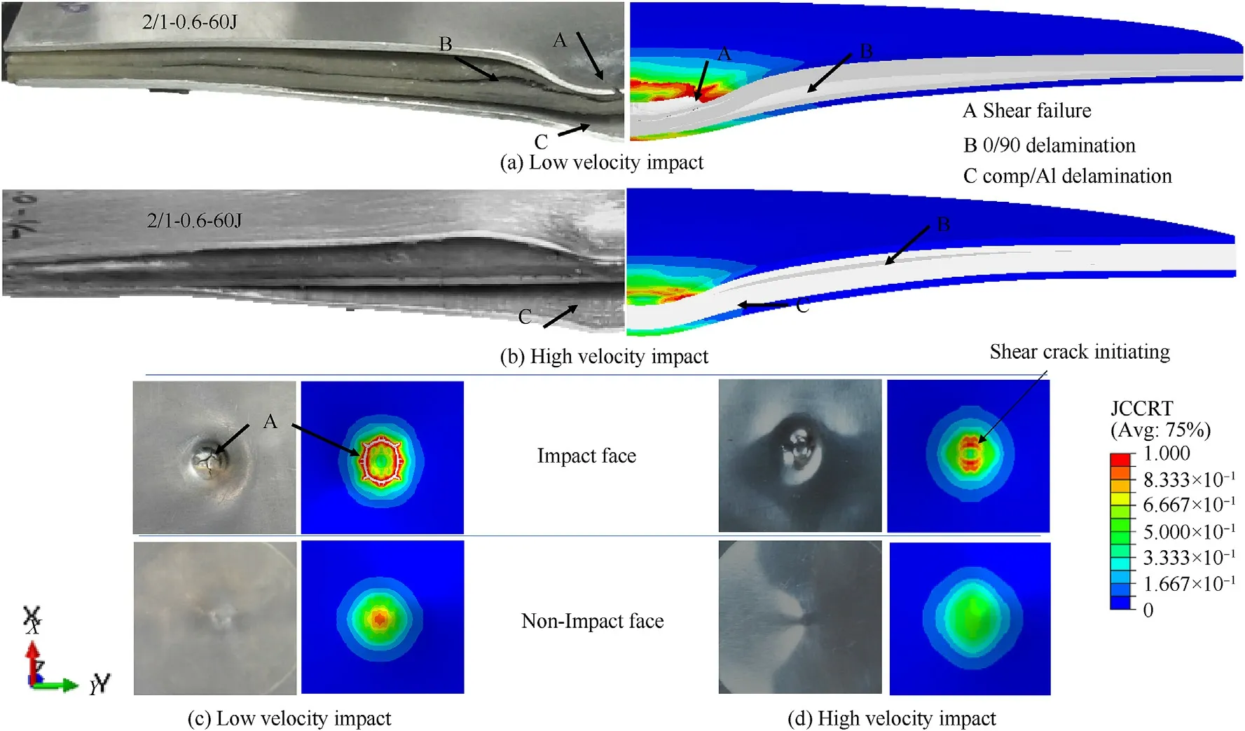
Fig.10.Delamination and shear failure in FML 2/1-0.6.
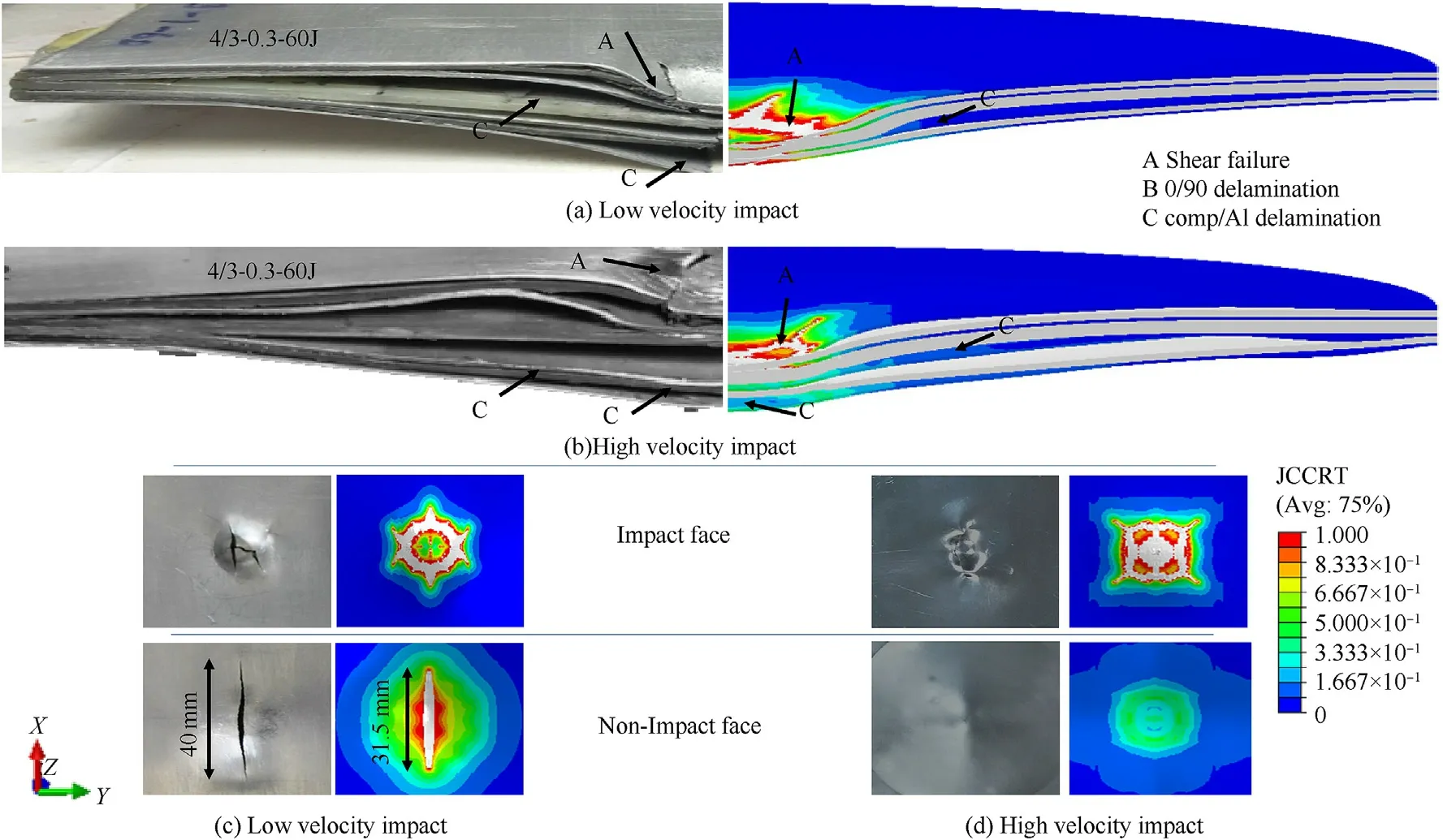
Fig.11.Delamination and shear failure in FML 4/3-0.3.
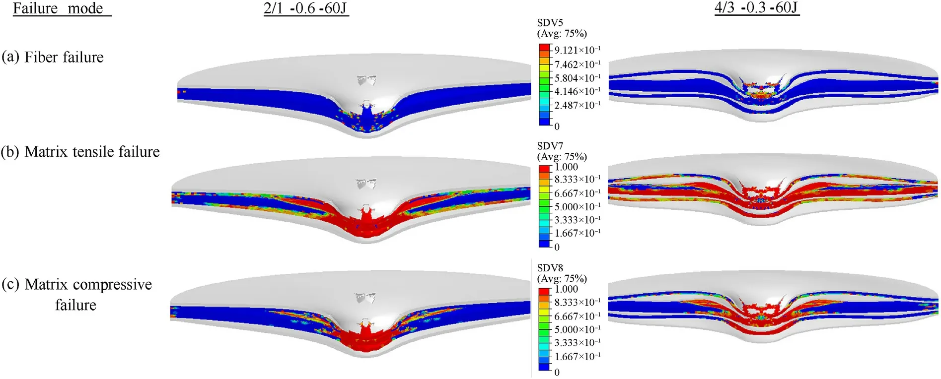
Fig.12.Failure modes in composite layers for the case of a high-velocity impact.
5.6.Damage energy
Different damage mechanism evolves in laminates during the impact even and these damage mechanisms dissipate energy.Various forms of energy that are dissipated during the impact of a projectile are delamination energy,matrix failure energy,fiber failure,metal shear failure energy,and energy corresponding to frictional losses.These all energies contribute to lowering the stiffness of the overall laminate but helps in preventing the structural failure of the laminate catastrophically.Understanding these energies’dissipation is crucial for a design engineer who can classify different laminates based on his requirement and costeffectiveness.Experimentally it will be dif ficult to monitor these energy dissipation processes as they are linked with each other and the damage phenomenon is dynamic and complex.Hence,we have followed a numerical route to separate and monitor these energy dissipation phenomena.The delamination energy is obtained by subtracting the overall energy(ALLDMD)with the metal layers energy(ALLJCCRT)while the energy dissipation for various failure modes occurring in composites are calculated inside the VUMAT by storing the portion of energy every time a failure occurs in the element for a particular mode in each increment.
The most important damage dissipation mode is delamination where almost 10%of the total impact energy is dissipated.Fig.13a shows the variation of delamination for the three laminates during the impact event.The energy dissipation is almost linear during the loading phase of the impactor for all three laminates while 4/3-0.3 laminates dissipate 26%more energy compared to the other two laminates.This is because of the additional metal layers placed symmetrically inside the layup.Further,it is also seen that the impactor took more time in the loading phase for 4/3-0.3 laminate,which is also noticed in section 5.2.Something similar happens in matrix failure mode too in which around 55%more energy dissipation is observed as noticed in Fig.13b for 4/3-0.3 laminate.It is to be noted that the matrix failure mode here consists of matrix tension and compression together.The matrix energy dissipation rate seems to be high initially for 4/3-0.3 laminate but not for 2/1-0.6 laminates.This shows that matrix failure occurs first in the middle 90layers accompanied by the delamination of adjacent metal layers in 4/3-0.3 laminates.Previous studies with experimental evidence have also shown that during the out of plane loading scenario matrix cracking phenomenon occurs first followed by adjacent interface delamination[101-103].The steep increase in the matrix energy dissipation after 400 us is accompanied by the fiber failure phenomenon for 4/3-0.3 laminate as seen from Fig.13c.This indicates the delay occurring in unloading the impactor.However,no fiber failure phenomenon is experienced by neither 2/1-0.6 laminate nor C-8L laminate.This shows that although the addition of metal layers inside the composite layup makes the laminate structurally weaker in strength however the overall energy absorption inside the laminates is increased.This is further veri fied by looking at the slope of frictional energy dissipation of the laminates as seen in Fig.13d in which the laminates having more metal layers in their layup were found to dissipate higher friction energy compared to C-8L laminate.
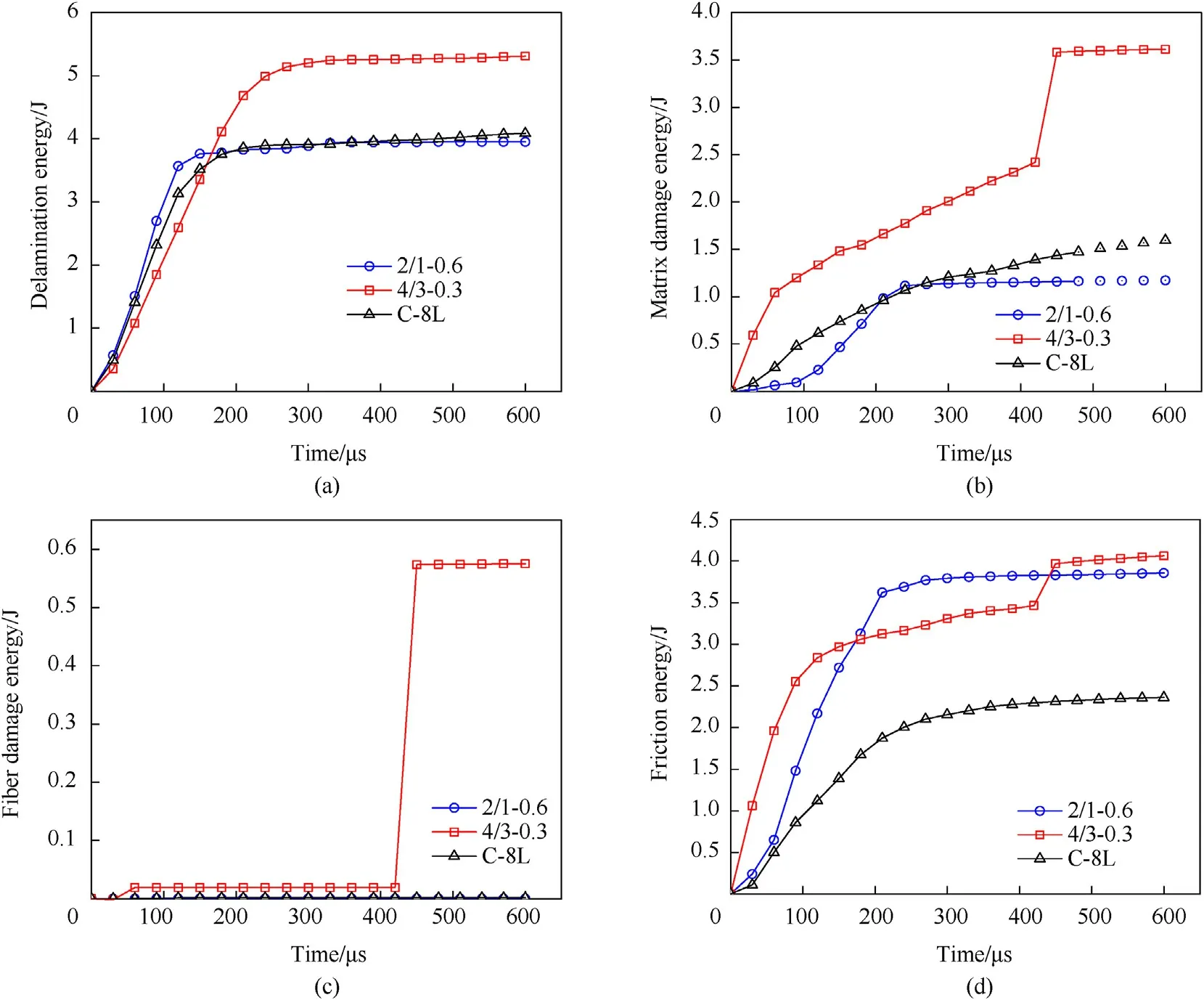
Fig.13.Energy dissipation in various failure mechanisms.
6.Conclusions
This study focuses on the effect of metal/composite interfaces inside the layups.The study is conducted on three types of laminates.In one of the laminates,only the top and bottom metal layers are sandwiched between[0/90]and called 2/1-0.6 laminate while in other,two additional metal layers are placed inside the layup and called 4/3-0.3 laminate.These two laminates are compared with an 8-layer composite layup having no metal layers and are called C-8L.The metal/composite interface is studied under a hemispherical projectile impact at a high strain rate.The study is conducted experimentally and veri fied numerically.The results are also compared with the low-velocity impact phenomenon studied earlier by the authors.
It has been observed that the 8-layer composite laminate performed best in terms of elastic recovery for lower impact energy.But when the damage of its laminates starts at a higher energy level the fiber failure mode was most prominent and this led to the structural failure of the laminates.However,when metal layers were added to these laminates,an additional plasticity effect is added to the layup of these laminates.The addition of the metal layers has been shown to improve the damage resistance of the laminates drastically especially at higher impact energy levels.This improvement has been made in terms of increased contact time of impactor,higher metal/composite interface delamination,and energy dissipation in metal shear failure.All these processes decrease the consequence of high-velocity projectile impact and make the structure more failure resistant.A comparative study of the effect of low velocity and high-velocity impact performed in this paper further enlarges the horizon of the mechanics of failure of these laminates.The outcomes of this study will help the design engineer to make an ef ficient decision on the choice of laminate(s)for his speci fic application.
The author(s)declared no potential con flicts of interest concerning the research,authorship,and/or publication of this article.
The authors are thankful to Prof P.Venkitanarayanan Dept.of Mechanical Engineering at IIT Kanpur for providing laboratory support and constructive suggestions on the outcomes of this study.The first author also acknowledges the computational facilities provided by the Computer Center(CC)IIT Kanpur India for the research carried out in this study.

- Defence Technology的其它文章
- High explosive unexploded ordnance neutralization-Tallboy air bomb case study
- Dynamics and rebound behavior analysis of flexible tethered satellite system in deployment and station-keeping phases
- Finite element analysis of functionally graded sandwich plates with porosity via a new hyperbolic shear deformation theory
- Investigation on the penetration of jacketed rods with striking velocities of 0.9-3.3 km/s into semi-in finite targets
- The effect of strain rate on compressive behavior and failure mechanism of CMDB propellant
- Adaptive target and jamming recognition for the pulse doppler radar fuze based on a time-frequency joint feature and an online-updated naive bayesian classi fier with minimal risk