
Numerical and experimental investigation on aluminum 6061-Vgrooved stainless steel 304 explosive cladding
2022-03-10 01:24:50WilsondhileepkumrSrvnnRghukndn
Defence Technology 2022年2期
C.Wilson dhileep kumr , S.Srvnn ,*, K.Rghukndn
a Department of Mechanical Engineering, Annamalai University, Annamalainagar, Tamilnadu, 608002, India
b Department of Manufacturing Engineering, Annamalai University, India
Keywords:Explosive cladding Dissimilar metals Grooves Numerical simulation Interface Strength
ABSTRACTThis study attempts to analyze the microstructure and interface behavior of aluminum 6061(Al 6061)-Vgrooved stainless steel (SS304) explosive cladding by numerical and experimental methods.Numerical simulation was performed by Smoothed Particle Hydrodynamics (SPH) technique, in ANSYS AUTODYN,and the results are correlated with experimental outcome.The machining of V-grooves on the base plate transform the melted layer formed in conventional cladding (without grooves on the base plate) into a smooth undulating interface,for a similar experimental condition.The flyer plate and collision velocities,observed in numerical simulation, are in good agreement to the analytical expectations.The pressure developed in the flyer plate is higher than the base plate and the maximum pressure is witnessed at the collision point irrespective of grooved base plate or otherwise.The temperature developed in the collision point of conventional explosive cladding exceeds the melting point of both the participant metals, whereas, it exceeds the melting point of aluminum alone, in case of V-grooved base plate cladding.The shear and impact strengths of the V-grooved base plate clads are higher than the conventional clads and the fracture surfaces exhibit mixed modes of fracture.
1.Introduction
In recent decade, aluminum-steel bimetallic clads are extensively employed in many engineering applications viz.,commercial and defense aircrafts,ship building and chemical industries due to its ability to reduce the structural components weight with improved corrosion resistance [1].However, joining of aluminumsteel by conventional fusion welding techniques is difficult due to the wide differences in physical and mechanical properties.In this context, solid state welding techniques viz., high velocity impact welding (HVIW), diffusion welding and friction welding offer reliable alternatives [2].Of the different HVIW methods, explosive cladding is more suitable to join aluminum-steel sheets,because of the duration of execution [3].Aizawa et al.[4]conducted experimental and numerical studies in aluminum 1100-low carbon steel explosive cladding and reported agreement in interface morphology between the two.In addition, they reproduced the local temperature distribution numerically.In a different study,Saravanan and Raghukandan [5]introduced an aluminum 1100 interlayer (0.5 mm thick) between aluminum 1100-stainless steel 304 plates and achieved higher clad strength.Recently, Carvalho et al.[6]employed low carbon steel and unalloyed niobium interlayer between aluminum AA6082-T6-stainless steel 304 plates and reported improved microstructure and strength characteristics.In another study, the same group of above researchers [7]characterized the aluminum rich intermetallic structures in the explosive clad interface (AA6082-stainless steel 304).
In explosive cladding, the understanding of the underlying mechanism of surface jetting phenomenon and wavy interface formation is complex, due to viz., explosion, dynamic collision,plastic deformation, extreme pressure and temperature development in duration of micro seconds [8].Hence, researchers attempted numerical simulation to understand the mechanism of explosive cladding.In an earlier study,Mousavi and Al-Hassani[9]simulated the explosive cladding process by Abaqus software and estimated the stress distribution.Kiselev et al.[10]studied the mechanism of interfacial wave formation by molecular dynamics and stated that the interfacial waves are formed by the self-induced oscillations at high pressure regions.In contrast, Wang et al.[11]attempted material point method to simulate the detonation of explosive,collision and interaction of participant metals,but failed to simulate the interface formation.Meanwhile, Sapanathan et al.[12]concluded that ALE equation is suitable for simulating straight interfaces and Eulerian equations are appropriate for wavy natured interfaces.In this context, Liang et al.[13]opined that the SPH technique is capable of replacing pure Eulerian approaches following its capability to simulate heavier distortion in a better fashion.In a different attempt,Liu et al.,in 2003[14]extended the SPH method to underwater explosive cladding and reported the similarity between experimentation and simulation.Likewise,Wang et al.,in 2012[15]determined the shear stress and effective plastic strain generated during explosive cladding of titanium alloys by employing SPH method.They further studied the underlying mechanism and the physical phenomenon of explosive cladding process and opined that SPH, a mesh less Lagrangian technique,is attractive and valuable for simulating larger distortion problems.Though few researchers attempted experimental[5-7,16]and numerical [4,17]studies on explosive cladding of aluminum-steel,numerical studies on the effect of V-grooved base plate in explosive cladding is scarce and hence attempted herein.In this study,SPH method available in ANSYS AUTODYN-2D is used to simulate the interface characteristics, distribution of physical parameters such as velocity, pressure and temperature during aluminum-V-grooved steel explosive cladding and the results are correlated with the conventional clads (without grooves on the base plate).In addition, the shear and impact strengths of the conventional and V-grooved base plated clads are determined and the results are presented.
2.Experimentation and testing
2.1.Experimental
Aluminum 6061 sheet having dimensions 110 mm × 50 mm ×3 mm and stainless steel 304 plates with dimensions 110 mm×50 mm×8 mm were employed as flyer and base plates respectively.The physical and mechanical properties of flyer and base plates are given in Table 1.V-grooves were machined along the transverse direction in the mating surface of the base plate(SS 304),prior to the cladding, as per the dimensions shown in Fig.1.A standoff distance of 5 mm was maintained between flyer and base plates, by keeping a spacer.A thin plywood sheet, employed as a buffer sheet,was placed above the flyer plate in order to protect the top surface from the ill effects of explosion.Sun 90 explosive(density,ρ=1.2 g/cm,detonation velocity,=4000-4500 m/s)was packed over the buffer sheet (5 mm thick) for a explosive loading ratio,(mass of the explosive/mass of the flyer plate)of 0.8 and detonated by an electric detonator positioned at one corner of the explosive.Four experiments were conducted for each condition(conventional,grooved base plate)and a sample explosive clad was shown in Fig.2.
Table 1Physical and mechanical properties of Al 6061 and SS 304 [18].
Fig.1.Cladding setup and dimensions of ‘V’ groove.
2.2.Microstructural analysis and mechanical testing
Subsequent to the experiments, the dissimilar explosive clads were sectioned along the detonation path and the microstructural specimens were prepared from initial, middle and end sections of the clad.All samples were ground and polished for 1 μm finish with different grades of emery sheets (600-1500 sieve sizes).The flyer and base plates were etched with Kellers reagent and 2% nital solution respectively.LEICA DM 4000 M optical microscope,LEO 440i Scanning Electron Microscope (SEM) and Philips X’PERT MPD diffractometer were used to characterize the clad interface.With respect to mechanical testing,Shear testing(ASTM B898 standard)was performed in a UNITEK-94100 Universal Testing Machine with a cross head speed of 0.5 mm/min.Charpy V-notch test specimens were prepared (Fig.3), as per ASTM E23 standard, and tested in a Charpy impact testing machine (ENKAY-SM 30) at room temperature (25C).Three sets of samples were fractured for each condition and average values are presented.The impact fracture surfaces were analyzed by SEM to determine the nature of fracture.
Fig.2.Explosive clad.
Fig.3.(a) Charpy impact test specimen (b) dimensions.
3.Numerical simulation
3.1.Geometry of the model
Numerical simulations were conducted in ANSYS AUTODYN (R 15) software employing mesh less SPH method.The initial configuration of the numerical simulation (material location), generated using Parts menu, is illustrated in Fig.4.Similarly, the material properties and explosive were added to materials library before processing.The initial conditions viz., standoff distance, preset angle, thickness of flyer and base plates were fixed through the initial conditions menu, while the boundary conditions viz., blast load, analytical boundary conditions were fixed by the Boundary conditions menu.The equation of state(EOS)and strength models for flyer and base plates were opted based on the nature and properties of the explosive and participant metals.In this study,ANFO explosive (detonation velocity 4160 m/s) was chosen as the energy generator which accelerates the flyer plate towards the base plate.The numerical simulation for the experimental conditions,detailed in section 2.1, were performed with flyer and base plates having dimension 110 mm × 3 mm and 110 mm × 8 mm respectively.
Fig.4.Preliminary arrangement for a grooved base plate cladding.
The SPH particles of ANSYS AUTODYN 2D,having an equal size of 30 μm was adopted.Hence, 2 million particles were employed, to simulate the process and to get insight into the mechanism of cladding and jetting phenomenon.The detonation point was positioned at one end of the explosive and gauge points are placed on the mating surfaces of flyer and base plates(Fig.4) to estimate the velocity, pressure and temperature effects.
3.2.Material strength model
The materials for flyer, base and explosive were selected from the material library available in AUTODYN,as per the experimental conditions.The Johnson-Cook constitutive relation was adopted to characterize the material behavior such as stress,strain rate and the temperature effects of the flyer and base plates.Johnson-Cook stress model was adopted for modeling and predicting the material flow behavior at elevated temperatures, and the Von-misses yield stress[σ]is given as [19,20].
Where εis the equivalent plastic strain,εis the plastic strain rate,εis the effective plastic strain,is the room temperature andis the melting temperature.andare different material properties, whose values are presented in Table 2.
3.3.Equation of state for material model and explosive
In this study,Mie-Gruneisen equation of state(EOS)is employed to describe pressure developed during shock compression on metals, expressed as [17].
where, μ is the relative change of volume, ρdenotes the initial density,is the bulk speed of sound in material,is the internal energy of the material per unit reference volume,is the first order volume correction to Gruneisen parameter γ,and,,,are the material constants, listed in Table 3.

Table 2Parameters of the Johnson-Cook material model for flyer and base plates.
Table 3EOS parameters of the participant metals.
The Jones-Wilkins-Lee (JWL) equation is used to explain the relationship between pressure and volumetric strain of the explosive, given by Refs.[4,21].
Whereis the pressure,represents relative volume, Eis the initial specific internal energy, and,,, andare JWL parameters and are shown in Table 4.
Table 4Parameters of the Jones-Wilkins-Lee model for explosive.
4.Results
The various stages of Al 6061-SS 304 and Al 6061-V-grooved SS 304 explosive cladding simulation,in a two dimensional space,are illustrated in Fig.5(a-d) and Fig.5(e-h) respectively.The detonation of the chemical explosive (Fig.5 a and Fig.5.e) initiates the propulsion and oblique movement of the aluminum flyer plate towards the stainless steel base plate.Subsequently, the impingement of the flyer plate with the base plate is visible,as the number of cycles increases.
4.1.Interface characteristics of conventional clad
The numerical simulation and the optical microstructure obtained at different locations of the conventional explosive clad(without grooved base plate) are shown in Fig.6.The interface of the numerical simulation resembles a straight and smooth morphology throughout the simulation, whereas a straight interface with a slender melted layer formation is witnessed in experimental microstructures.
The final stage (32550 cycles) of the Al 6061-SS 304 explosive cladding numerical simulation, for a loading ratio of 0.8, in a two dimensional space is shown in Fig.6 a.For better visualization,the dispersion of SPH particles in the explosive is hidden.The magnified image at the initial, middle and tail stages of the process are also shown at subsets.The morphology of the interface at different sections of the interface displays a marginal variation,resembling a straight nature throughout (Fig.6.a).In addition, the ejection of metallic atoms in the form of’Jetting’is not visible,consistent with the reports of Sun et al.[22], who cladded TA2-Q235 sheets.
The experimental microstructures at different locations of the conventional dissimilar explosive clad are shown in Fig.6(b-d).The interface microstructure obtained from the initial section(20 mm from detonator end) display a straight interface (Fig.6 b)with no visible presence of melted layer.However, a continuous melted layer having a thickness of 25-40 μm is witnessed at the middle section (50 mm from detonator end) of the clad (Fig.6 c).The presence of melted layer holds a negative influence on the clad strength and is attributed to the dissipation of available kinetic energy, which is transformed into heat at the interface [23].The kinetic energy dissipated (Δ) at the interface is estimated by Ref.[24].

Where mand mcorresponds to the weight of flyer and base plate per unit area respectively andis the flyer plate velocity.In addition to kinetic energy,the quantum of plastic deformation also contributes to the formation of melted layer as well[25].At the tail section of the clad (80 mm from detonator end), the thickness of molten layer further increases to 45-55 μm(Fig.6 d).The variation in the thickness of melted layer across the interface is consistent with the reports of Ather et al.[26].The distinct variation in density and thermal conductivity of the participant metals contributes to the disparity in melted layer thickness, as the rate of heat transfer from the interface to the participant metals is not uniform.The heat emanating at the interface is transmitted on both sides, based on their thermal conductivities.The thermal conductivity of aluminum(167 W/mK)is tenfold higher than stainless steel(16 W/mK), which indicates that the heat will be transmitted on the aluminum flyer, more rapidly than the stainless steel base.The disparity in density (three times) of participant metals also contributes to the non uniform distribution of heat.The XRD analysis(Fig.7), performed on the melted layer confirms the presence of large proportions of weaker parent alloy aluminum and the presence of reaction compounds viz.,FeAland AlFe,consistent with the Al-Fe phase diagram and the reports of earlier researchers[27,28].
4.2.Interface characteristics of Al-V-grooved base plate
The machining of V-grooves on the base plate promote a wavy interface, thereby, a significant change is achieved in numerical simulation and experimental microstructures (Fig.8).In the numerical simulation for the similar experimental conditions(LR-0.8,Standoff distance-5 mm), straight interfaces are observed in the initial stages of collision (Fig.8.a).However, after 5000 simulation cycles interfacial waviness begin to form following the initiation of jetting from the interface.Li et al.opined that the formation is jetting is mandatory for an undulating interface[29].It is observed that the interfacial amplitude increase with the duration of collision,and the maximum amplitude is witnessed at the tail section of the simulation.The increase in interfacial amplitude is attributed by the pressure developed at the collision point [30](detailed in section 5.3).
The experimental microstructures obtained from initial,middle and tail sections of the dissimilar explosive clad are shown in Fig.8(b-d).The grains witnessed in the closer proximity of the interface are finer than those away from the interface as in earlier reports [31,32].The melted layer formed in conventional cladding,detailed in the previous section, is transformed into a smooth interface, devoid of ’melt’ region.As the machining of grooves on the base plate increases the contact area between flyer and base plates,the kinetic energy utilization in moving the flyer plate into the grooved portion which is otherwise used for melting the participant metals is enhanced, as reported by Kumar et al.[18].
Fig.5.Stages of numerical simulation (a-d) conventional clad (e-h) V-grooved base plate clad.
The interface micrograph obtained between grooves, in the initial stages of collision in the detonation direction, display a straight interface(Fig.8 b:15 mm from detonator end),as obtained from numerical prediction.Likewise, the experimental microstructure obtained at the mid section(45 mm from detonator end)of the clad show a smooth undulating interface with a wavelength and amplitude of 135 μm and 25 μm respectively (Fig.8.c).In the tail sections of the clad(Fig.8 d:85 mm from detonator end),wavy interfaces are more pronounced with a nearly 40% higher wavelength(185 μm)and amplitude(35 μm).The enhancement in amplitude is due to the steep increase in shear stress and the pressure developed, and is consistent with the findings of Yuan et al.[33].The microstructure obtained from the vertical section of the grooves (Fig.8.e) show a slender presence of reaction compounds (10 μm), while the bottom portion of interface exhibit a smooth interface (Fig.8 f) free from any intermetallic compounds or melted regions.It is inferred that the machining of grooves inhibits the molten layer formation and enhances the strength of the clad (detailed in the next section) and thus advantageous.
4.3.Mechanical strength
The shear and Charpy impact strengths of the dissimilar explosive clads with and without grooved base plate are shown in Fig.9.The shear and impact strengths of explosive clads, for all attempted conditions,are higher than the weaker of the participant metals(Al 6061),as reported by Yazdani et al.[34].The V-grooved base plate dissimilar explosive clad reaches shear strength of 242 MPa,while the conventional one(no grooves on the base plate)attains 210 MPa.The significant variation is attributed by the strong interlocking on the grooved region and the presence of melted layer in conventional cladding.Saravanan and Raghukandan opined that the introduction of grooves enhances the kinetic energy utilization,thereby supporting the enhancement in strength, consistent with this study [16].
During impact testing, samples fractured on the stainless steel side,whereas the flyer plate was bent,and not fractured as shown in Fig.10.Further,flyer plate peeling was visible in the conventional cladding (Fig.10 a), whereas no visible spalling was evident in the clad having a grooved base plate (Fig.10 b).
Fig.6.Conventional explosive cladding (Al 6061-SS 304) (a) Numerical analysis.(b-d) experimental microstructures at a distance of (b) 20 mm (c) 50 mm and (d) 80 mm.
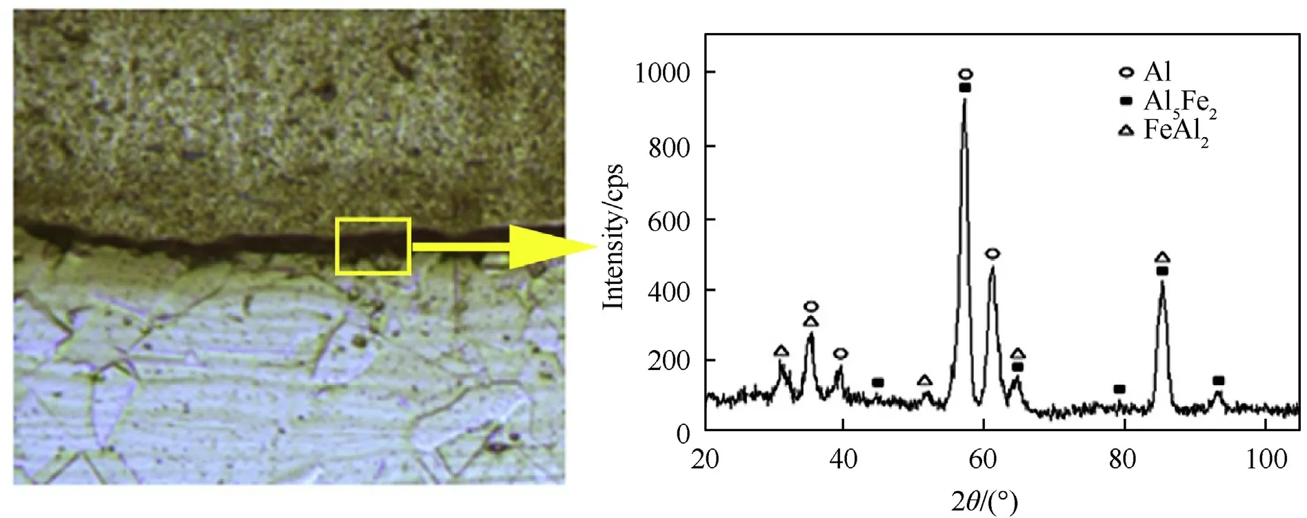
Fig.7.XRD analysis on the conventional clad interface.
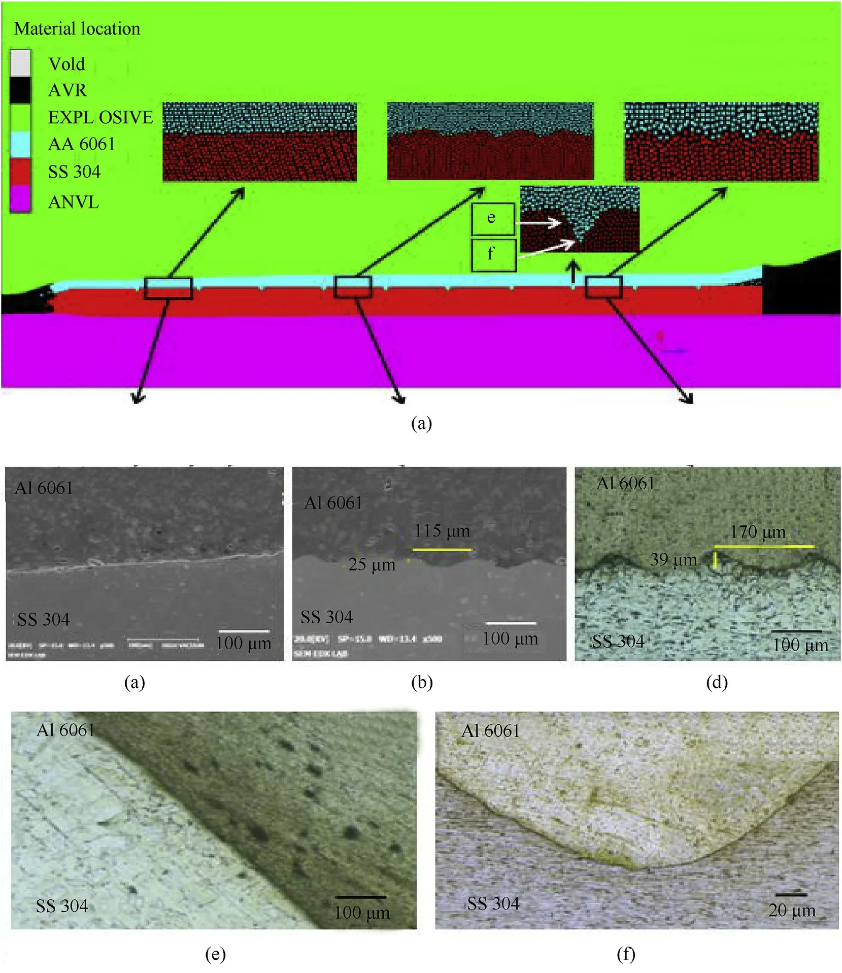
Fig.8.(a) Al 6061 - V- grooved SS304 clad interface during simulation.(b-f) experimental microstructures at (b) 15 mm (c) 45 mm (d) 75 mm (e-f) groove.
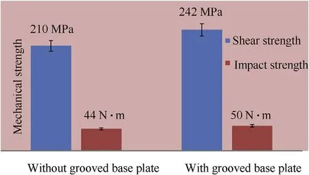
Fig.9.Mechanical strength of the explosive clads (Al 6061-SS 304).
The impact strength of the dissimilar explosive clad with a grooved base plate (50 N-m) is 13% higher than the conventional explosive clad (44 N-m).The reduced impact strength in conventional cladding is due to the presence of melted layer (seen in section 4.1), is consistent with the reports of Manesh and Taheri[35].However, the minimum impact strength is 12% higher than the weaker aluminum 6061 flyer plate as reported by Robin et al.[36].
The impact fracture surface of dissimilar explosive clads with and without grooved base plate exhibit a mixed mode of failure,as shown in Fig.11(a&b).The fracture surface portrays a brittle and a small proportion of dimples fracture modes, thus indicating the occurrence of plastic deformation prior to failure which enhances the impact strength of the explosive clads.
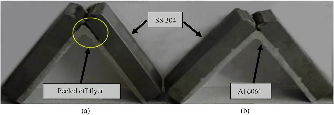
Fig.10.Fractured impact test specimens (a) Al 6061-SS 304 (b) Al 6061-V-grooved SS 304.
Fig.11.Fracture surface of (a) conventional clad (b) V-grooved base plate clad.
5.Discussion
5.1.Jet formation
The magnified views of the dissimilar explosive cladding simulations with and without V-grooves on the base plate are illustrated in Fig.12.Formation of jetting, mandatory for a wavy interface, is evident in both conventional and grooved base plate cladding.Jetting sweeps the top layer of the mating surfaces and promotes bonding of virgin surfaces at atomic level [37].The quantity of jet ejection is higher in conventional cladding(Fig.12 a)than the V-grooved base plate cladding(Fig.12 b).The reduction in the V-grooved base plate is due to uniform pressure distribution and the availability of additional spaces (through grooves) for expulsion.In addition, the V-grooved space enhances the kinetic energy utilization and aids in preventing the jet trapping and thus promotes a defect free clad.
The concentration of weaker parent alloy(aluminum)is higher in the ejecting jet, irrespective of the surface preparation of the base plates (grooved or otherwise) and is consistent with the reports of Bataev et al.[38].In high velocity collision the participant alloy having lower density (aluminum: 2700 kg/m) experiences maximum deformation and leads to the higher concentration in the ejecting jet.In addition, the concentration of metals in jetting depends on the physical properties of participant metals, impact velocity, standoff distance and collision velocity [39].
Fig.12.Jet formations during (a) Conventional cladding (b) V- grooved cladding.
5.2.Velocity distribution
The flyer plate velocity, another significant factor in explosive cladding, dictates the magnitude of plastic deformation created at the interface.The flyer plate velocity profile,obtained in numerical simulation, in the Y-direction is shown in Fig.13.In the velocity profiles, gauges 25, 27 and 29 represent conventional cladding,whereas the gauges 31,33 and 34 denotes the data extracted from the flyer plate employed in the V-grooved base plate cladding.In the numerical simulation,the maximum flyer plate velocity in the Y direction varies from 850 m/s to 900 m/s, consistent with the analytical estimation (874 m/s) given by Ref.[40].

Where β, the dynamic bend angle can be calculated using expression [41].

Where,is the thickness of explosive, andis a constant ranges from 1.96 to 2.8 depending on the thickness of chemical explosive.Hence it is inferred that the SPH simulation is capable of predicting the flyer plate velocity effectively.
The collision velocity profiles of the Al-SS 304 and Al-Vgrooved SS 304 explosive clads after 17000 cycles of simulation is shown in Fig.14.The collision velocity in conventional groove less and V-grooved base plate cladding records 4120 m/s and 4420 m/s respectively, which is 9% and 1% closer to the theoretical collision velocity and which is equivalent to the detonation velocity of the explosive[42].The machining of grooves on the mating surface of the base plate increases the collision velocity by 7%.The closer prediction of collision velocity in numerical simulation is consistent with the studies of Mousavi and Sartangi [9].The increase in collision velocity is attributed by the augmentation in collision angle from 22to 24for a grooved base plate cladding.In concurrence with the inference of Manikandan et al.[43],this study proves that the collision angle is directly proportional to the collision velocity of the flyer plate.
Fig.13.Flyer plate velocity profile.
5.3.Pressure distribution
The pressure contours during the initial stage of cladding, with and without grooved base plates, are shown in Fig.15.The maximum pressure is witnessed at the collision point while there is no significant increase in pressure in other regions of the clad.This supports the analogy that explosive cladding is a solid state metal joining process.The high pressure developed at the collision point creates a plastic deformation and induces jetting [44].
It is found from the numerical simulation that the pressure developed at the collision point (>15 GPa) exceeds the dynamic elastic limits of participant metals (Al 6061 and SS 304) to attain plastic deformation.The maximum pressure at the collision point in conventional Al 6061-SS 304 explosive cladding (without grooved base plate)is 17.44 GPa,which declines to 16.38 GPa when a V-grooved base plate is employed.In addition, a localized pressure distribution is witnessed around the collision point (Fig.15a)in conventional cladding, whereas uniform pressure distribution around the collision region is seen with the grooved base plate cladding(Fig.15 b).The variation in pressure distribution is due to increase in collision angle as reported by Mousavi and Al-Hassani[9].The pressure,developed in the detonation wave front is analytically estimated by Ref.[45].

Where ρis the initial density of the explosive andis the polytropic index ranging from 1.5 to 3, depending on the initial density and chemical composition of the chemical explosive.Based on the empirical relation,the pressure developed at the detonation front is 7.67 GPa, which is closer to the numerical simulation,indicating the effectiveness of numerical simulation.
The pressure curves for conventional and grooved base plate explosive cladding (Fig.16) show humps and hollow in the distribution of pressure, which steadily increases in the detonation direction.The pressure distribution in flyer (25 and 34) and base (5 and 14)plates are determined by considering the gauge points(face to face).
It is seen that the pressure experienced by the flyer plate is higher than the pressure developed on base plate, for the entire numerical simulation.The higher pressure in flyer plate is due to its closer proximity with the chemical explosive and its active participation in the plastic deformation.
5.4.Temperature distribution
The temperature distribution in the closer proximity of the interface during the numerical simulation of conventional cladding is shown in Fig.17 a.It is evident that thermal effects are more pronounced at the interface region as similar to the pressure contour.There is no significant increase in temperature away from the interface.The maximum temperature at the interface reaches 1873 K, which is higher than the melting points of participant metals (Al 6061-933 K and SS 304-1523 K).This is in agreement with the reports of Bataev et al.[38].Subsequent to the high temperature, localized melt regions are observed at both sides of the interface, as seen in the experimental results (detailed in section 4.1).In addition, the high localized pressure developed in the collision region (detailed in the previous section) enhances the temperature as well.
Fig.14.Velocity contours during simulation in (a) conventional (b) V-grooved.
Fig.15.Pressure distribution during detonation in (a) conventional (b) grooved base plate.
Fig.16.Pressure time curves during simulation of (a) conventional (b) grooved base plate.
The temperature developed at various locations of the participant metals is analytically estimated by the empirical relation[46].

Fig.17.Temperature distribution (a) conventional clad (b) V-grooved base plate.
Where,- temperature of the clad at a distance X (m),-atmospheric temperature (K), Q is the quantity of heat released at time=0,c-specific heat(J/kg/K),ρ-density(Kg/m),α-thermal diffusivity (m/s).The temperature developed at the interface,determined analytically,is 5%lower than the numerical prediction.
In case of grooved base plate cladding(Fig.17 b),the interfacial temperature and the ejecting jet attain 1540 K which is higher than the melting point of weaker parent alloy (aluminum), but lower than the melting point of stainless steel.However, as the interface temperature exceeds the flyer plate, it starts to melt earlier and results more concentration in the jetting.The lower density of aluminum also contributes to this phenomenon as stated by Grignon et al.[47].Further, the machining of grooves reduces the interface temperature by 21%, than conventional cladding.This leads to lower thermal energy available and the enhancement in plastic deformation work.The reduction in temperature development at the interface inhibits the melted layer formation,as seen in experimental microstructure, and thus advantageous.
6.Conclusions
1.Machining of grooves inhibits the melted layer formation due to the enhanced deformation work and reduced thermal effects at the interface of the explosive clads.
2.The grooved base plate reduces the pressure and temperature developed at the interface of the explosive clads.
3.The collision velocity predicted by the numerical simulation 1%lesser than the analytical estimation, and thus effective.
4.Grooves machined on base plate suppress the intermetallic formation at the interface due to enhanced kinetic energy utilization.
5.Explosive clads having V-grooved base plates show higher shear and impact strength than the conventional explosive clads.
The authors declare that they have no known competing financial interests or personal relationships that could have appeared to influence the work reported in this paper.

- Defence Technology的其它文章
- Effect prediction of stiffened-ring cylindrical shells subjected to drop mass impact
- Study on the influence of armature on the efficiency of reluctance accelerator
- Research on a combinatorial control method for coaxial rotor aircraft based on sliding mode
- An optimization method for passive muzzle arc control devices in augmented railguns
- A capture probability analytic model for the electromagnetic launched anti-torpedo torpedo
- Optimal control based coordinated taxiing path planning and tracking for multiple carrier aircraft on flight deck