
Effect prediction of stiffened-ring cylindrical shells subjected to drop mass impact
2022-03-10 01:25:06ShengzhuoLuJingxinMaLanLiuChunlongXuShiboWuWeidongChen
Defence Technology 2022年2期
Sheng-zhuo Lu, Jing-xin Ma, Lan Liu, Chun-long Xu, Shi-bo Wu, Wei-dong Chen
College of Aerospace and Civil Engineering, Harbin Engineering University, Harbin,150001, PR China
Keywords:Drop mass impact Stiffened ring Cylindrical shell Impact load Dynamic response Parametric studies
ABSTRACTThis study focuses on the effect of lateral mass impact on ring-stiffened thin-walled cylindrical shell.Cylindrical shells were fabricated to validate the numerical modeling and analytical techniques,and drop tests were performed using a rigid spherical indenter.Next,stiffened-ring cylindrical shells with various structural size parameters were simulated using ABAQUS software.The relationships between the impact force, deformation displacement, and rebound velocity were established, on the basis of impact mechanics theory and simulation results.It derived fitting functions to analyse the relationship between the maximum load and maximum displacement of ring-stiffened cylindrical shell under dynamic mass impact.Based on the validation of the simulation model, the fitting function data were compared with the simulation results, and the functions showed a good accuracy.Besides, the parameters, mass ratio and stiffened-ring mass ratio were used to reflect the effect of the mass change in the ring-stiffened cylindrical shell.Furthermore, parametric studies on ring-stiffened cylindrical shell models were conducted to analyse the progressive impact responses.
1.Introduction
Wide-diameter thin-walled cylindrical shells are widely used in several industrial applications, such as structural components of offshore platforms, energy storage vessels, and submarine structures.Sometimes, cylindrical shell structures are subjected to accidental impact.Such loads are induced by mass impact or impulsive pressure loading during accidents [1,2].For example,ships and offshore structures at sea are exposed to risks of ship collision and impact from dropped objects,which cause significant economic loss, severe environmental pollution, and fatalities.The huge losses from several catastrophic marine collision accidents,such as the sinking of the Titanic after hitting an iceberg and the explosion of the Mumbai High North platform after experiencing collision with a supply vessel have aroused public concern regarding the operational safety of ships and offshore structures[3-6].Energy storage vessels,such as oil storage and liquid natural gas tanks,are prone to damage caused by severe accidents,such as earthquakes and accidental explosions.According to some previous records on accidents [7], vessels experienced severe damage from the impact of projectiles and the collision of nearby collapsed structures [8,9].
Stiffener structures are widely used in safety engineering for military and civil purposes.Large cylindrical structures are reinforced using stiffeners, such as rings (circumferentially) and stringers (axially),to satisfy lightweight requirements and achieve structural efficiency.Ring stiffeners are useful for strengthening cylindrical shells against external pressure loading.The stiffener or stiffened rings may minimise the impact effect and protect the entire structure.
Several researchers have investigated the buckling behaviour of stiffened structures [10-18].However, only a few studies on the behaviour of ring-stiffened cylindrical shell under mass impact have been conducted.

?
Ronalds et al.[19,20]performed quasi-static denting tests on four small-scale stringer-stiffened cylinders under lateral loads at the mid-span.The damage was simulated by slowly applying a round-edged wedge to the cylinder radially,with the edge normal to the cylinders axis.The specimens were then axially loaded in small increments using a displacement-loading machine.Walker et al.[21,22]performed quasi-static denting tests on two stringerstiffened cylinders denoted as R5 and R6.These models had three bays each, separated by a plain-section circumferential ring stiffener and stiffened in the longitudinal direction using 40 and 20 stringer stiffeners, respectively.The tests were performed on this shell geometry to further investigate the initial tripping of stiffeners under hydrostatic pressure, and the cylinders were then subjected to axial compressive loads.Cerik [23]numerically predicted the residual strength values of damaged string-stiffened cylinders subjected to axial compression.The local denting damage was evaluated through dynamic denting analysis of a lateral load, and the cylinders were then subjected to axial compression.An advantage of applying quasi-static denting to impose specified damage is that it enables the continuous recording of the damage process, which can be applied to develop simplified analysis methods.Cerik[24-27]focused on the load-carrying behaviour of large-diameter thin-walled stiffened cylinders with local damage under axial compressive loads.To assess the factors influencing the ultimate strength reduction under axial compression and analyse the progressive collapse behaviour, the researcher designed ringand-orthogonally stiffened cylinders, considering both intact and damaged conditions.
In addition, Do and Muttaqie assessed the impact responses of wide-diameter, thin-walled steel stringer-stiffened cylinders subjected to low-velocity mass impact.Two steel stringer-stiffened cylinders were fabricated, and drop tests were performed at midspan using a rigid knife-edged indenter.Parametric studies on stringer-stiffened cylinder models were conducted to clarify the progressive impact responses.They also derived a formulation for predicting the permanent damage of steel ring-stiffened cylinders subjected to dynamic lateral mass impact.Drop tests on four cylinder models were performed using a knife-edge indenter to generate the damage.Next, all the models were subjected to hydrostatic pressure tests to assess their ultimate strength under damaged and intact conditions.Simple design equations for predicting the degree of local denting damage and the residual strength of damaged ring-stiffened cylinders were derived[28-30].Cho provided details of the experimental and numerical results for both intact and damaged ring-stiffened cylinders.The dynamic mass impact generated the damage, and the residual strengths of the cylinders under hydrostatic pressure were determined [31,32].Rabczuk introduced a coupling method for treating fluid-interaction of fracturing structures under impulsive loads.In his method, both fluid and structure are treated by mesh free methods.The method is aimed at problems with high-pressure and low-velocity fluids, and numerical simulations of cylindrical shell impact and fracture were conducted by his method.Besides,he also used a meshfree method in modeling a thin shell cracks [33,34].With recent advances in computational tools and considering the difficulty in conducting experimental investigations, non-linear finite element analyses have become the preferred method for assessing the conditions of mechanically damaged steel-stiffened structures [35-38].
Relatively few analytical studies have been carried out on the prediction of local denting deformation to assess the extent of ringstiffened cylindrical shell damage.Moreover, the relationship between the cylindrical shell response and the mass impact effect has not been investigated in detail.The purpose of this study is to analyse the response of a stiffened-ring shell under a bulk mass impact.More attention is concentrated on the structures’response under low velocity impact, like drop impact or collision.Based on the simulation work validation, stiffened-ring cylindrical shells with different structural size parameters were established in ABAQUS.This study focuses on the relationship between the impact force and deformation displacement, and rebound velocity, based on the impact mechanics theory and simulation results.
2.Theoretical analysis of drop weight impact
During the drop weight tests,the relationship between the drop mass and the impacted structure experiences the following stages.
2.1.Freefall
As shown in Fig.1, the drop mass freely falls from a specific heightand contacts the surface of the specimen.If the energy loss(e.g., friction between drop mass and frame or others) is ignored,the initial impact velocityis derived from the energy
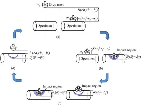
Fig.1.Flow chart of drop impact and structure response.
conservation relationship in Eqs.(1) and (2).
In Eq.(1),is the mass of the drop mass in the test machine,andis the initial kinetic energy.
2.2.Compression

2.3.Rebound

3.Material and methods
3.1.Drop weight test machine
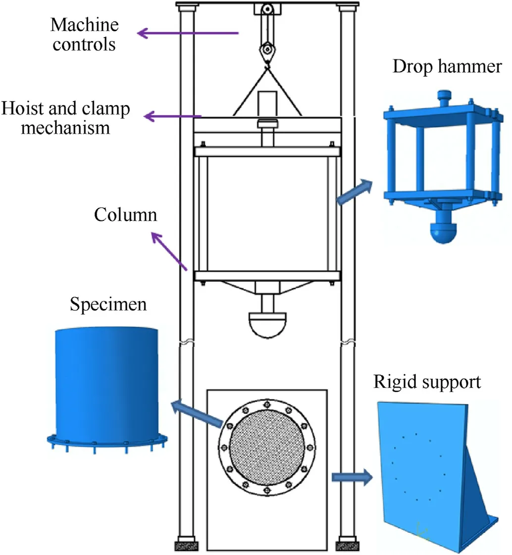
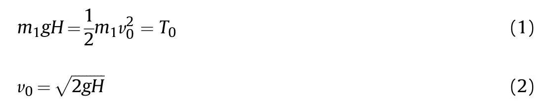
Fig.2.Schematic of drop weight impact tester.
A schematic of the drop weight impact tester used in this study is shown in Fig.2.The tester consisted of two main parts: the mechanical structure and instrumentation system.The mechanical structure or frame consisted of a drop hammer, guided by two guide columns.The hammer could be raised over two columns to a suitable height using a hoist and clamp system and then allowed to fall to impact the specimen fixed on the rigid supporting platform.The maximum release height of the drop hammer was 20.6 m,and it fell along the smooth guide columns immediately the electromagnet (hoist and clamp mechanism) was released manually.Three types of steel indenters (hemispherical, wedge-shaped, and cylindrical) can be changed for tests on different types of specimens.The details of the indenters can be found in Reference [39].The drop hammer weight varies from 380 to 1090 kg.In this study,the spherical indenter was selected, and the total weight of the drop hammer was 400 kg.The applied loading rate was varied by dropping the hammer from different heights.
The instrumentation system consisted of different sensors and a data acquisition system.The system components were as follows:(1)a piezoelectric force sensor(the load cell mounted between the indenter and drop hammer) to measure the applied impact force acting between the hammer indenter and the specimen; (2) a magnetic strip (mounted on the column) and a magnetic sensor(fixed on the side of the hammer) to detect the position of the hammer along the column; (3) the data acquisition system comprising a signal collection instrument, signal conditioner, and computer.
In addition, a high-speed video camera of the Phantom brand was used to monitor the entire deformation process at a speed of 2000 frames per second.The testing instruments,such as the load cell and magnetic sensor, are depicted in Fig.3.
3.2.Design of specimen
The specimens were fixed to rigid steel support, which was bolted to the rigid supporting platform.The rigid steel support was composed of a vertical plate, horizontal plate, and ribbed plates(Fig.2).A total of twelve M10 bolt holes(diameter=10 mm)were drilled in the vertical plate (at every 30) to fix each specimen.In addition, the rigid support was connected to the rigid supporting platform through two rows of M32 bolts (diameter= 32 mm).Thus,the movement of each specimen and the rigid support during the drop impact tests were strictly restricted.
Fig.3.Drop test facility and testing instruments.
According to the specimen design, the cylindrical shell was cut out from the selected steel sheets, cold-rolled to the required radius, and welded through longitudinal seam welding.Additionally,φ 6 steel rebar(diameter of section=6 mm)was adopted as the stiffened ring and combined with the shell.The rings were welded on the inner surface (Fig.4(a)).Fig.4(a) shows a group of test models,i.e.GA before the impact test,and Fig.4(b)shows the distribution of rings inside the models.
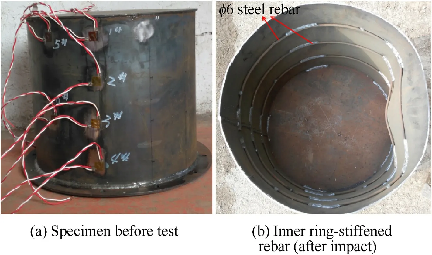
Fig.4.Specimen of GA models in test.
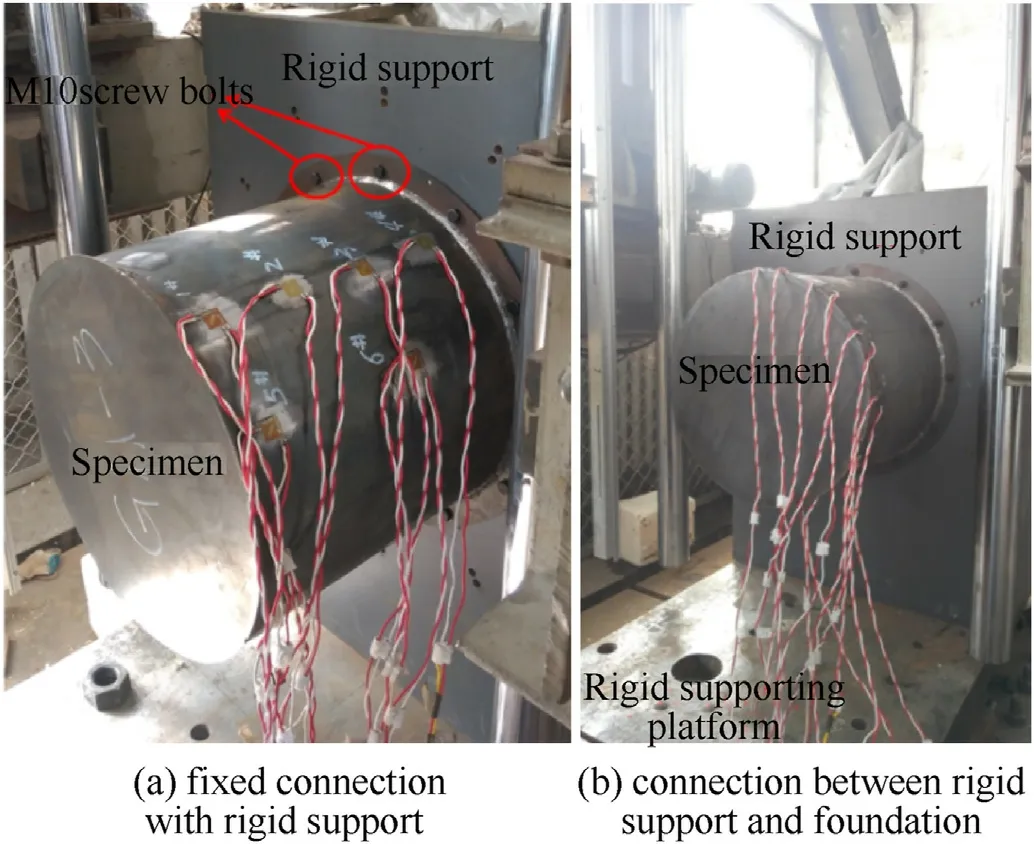
Fig.5.Fixed condition between test specimen and rigid support.
Based on test models GA, the shells were cut from 2 or 3 mm thick steel sheets, cold-bent using rollers, and welded to form cylindrical shells.There were three ring stiffeners in each specimen,and the spacing was-mm.A 3 mm thick circular plate was welded onto the cylindrical shell bottom, and its outer diameter was larger than the cylindrical shell size (the distance was).
Twelve holes were drilled at the bottom plate to bolt the rigid steel support.Each hole was drilled at intervals of 30around the bottom plate margin.Each specimen was fixed to a 30 mm thick rigid plate (rigid support part in Fig.5(a)) using M10 (diameter=10 mm)screw bolts(matching with the hole).A detailed view of the boundary conditions is depicted in Fig.5(b).
The axisymmetric geometry of the specimen is shown in Fig.6,and the details of the related parameters are listed in Table 1.
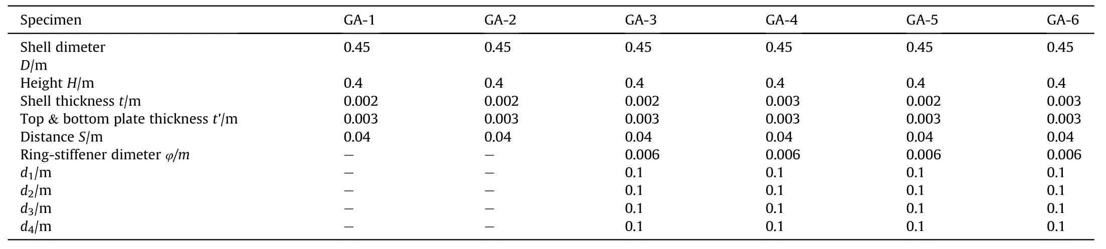
Table 1Dimensions of group GA models in the test.
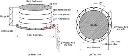
Fig.6.Design of the test specimen.
A magnetic sensor(fixed to the drop hammer)and strip facility were used to capture the movement of the spherical indenter during the test (Fig.3).The auxiliary measurement tool, TEMA Motion (Version 3.7 produced by Adept Turnkey Company) was also used to track the camera videos and analyse their traces.Information on the spherical indenter movement can be obtained from TEMA track results.Figs.7 and 8 show comparisons of the drop displacement (absolute value) between the magnetic sensor and the TEMA tool.The relative difference between the two measurements did not exceed 9%.Furthermore, other essential track parameters, such as instant drop velocity, could be obtained from the TEMA analysis results, as follows.
Fig.9 depicts the impact force history curves plotted from the load cell during the tests.In addition, it also describes the instant velocity variation of the spherical indenter from TEMA motion track analysis.After the indenter impacted on each specimen, the velocity curve started to decrease from the maximum value.Next,the velocity was zero when the indenter had the same velocity,with the impacted area (i.e.the compression stage, as described in Section 2(b)).Almost at the same time,the maximum value of the history curve of the impact force was reached.Subsequently, the deformed structure accelerated the rebound of the indenter.The velocity curve started to increase in the opposite direction until it reached the maximum negative value(orof the rebound and restitution stage,described in Section 2(c)).The indenter was then separated from the specimen,and the impact force curve declined to zero.The test conditions and related test parameters are listed in Table 2.
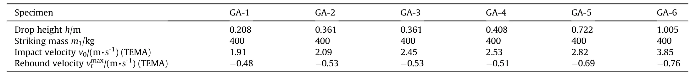
Table 2Impact test conditions for the GA specimens.
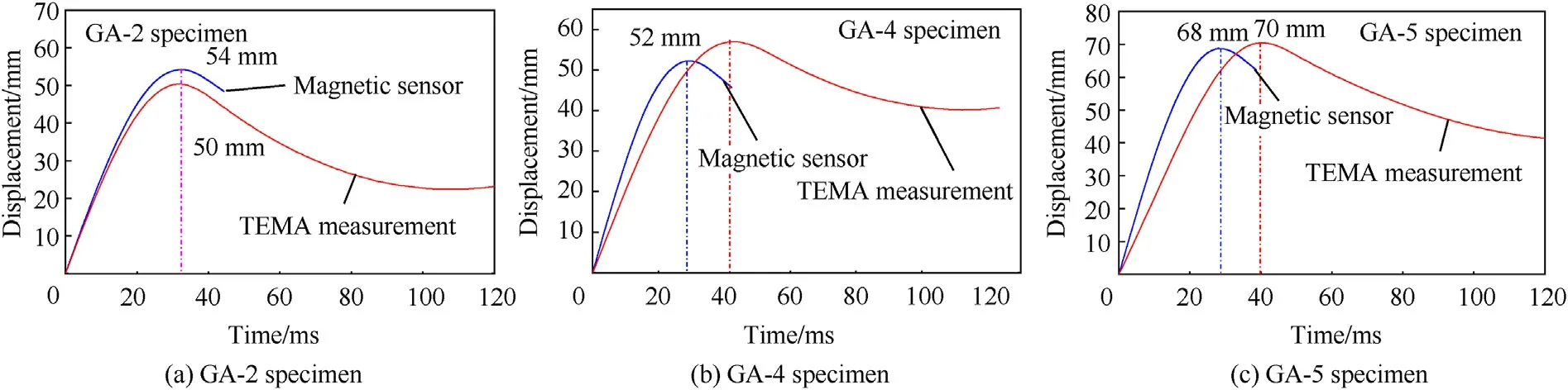
Fig.7.Comparison of spherical indenter displacement curve.
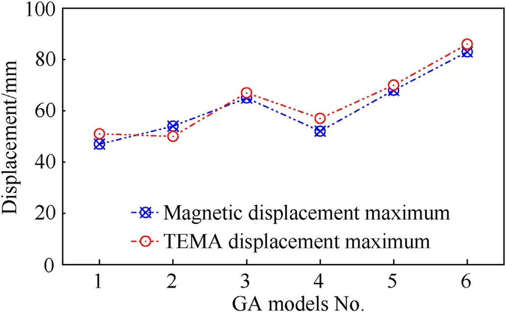
Fig.8.Maximum value comparison between magnetic sensor and TEMA track.
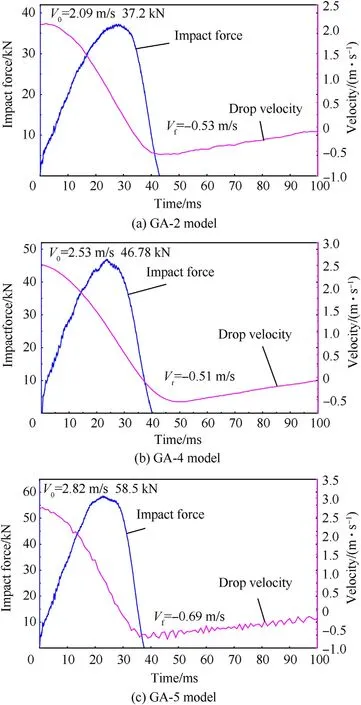
Fig.9.Impact force and indenter velocity from TEMA analysis.
4.Numerical simulation
4.1.Numerical model setup in ABAQUS
The simulation models were established using ABAQUS Version 6.16.As explained in Section 3.1, the drop hammer, specimen, and rigid support facility were considered in the simulation environment.The simplified model was built to achieve simulation accuracy and calculation efficiency (Fig.10).The drop hammer was simplified as a spherical mass, and its total weight (mass= 400 kg) was concentrated at its centroid (Fig.10).As the specimen was fixed to the rigid support facility with bolts,the rigid support facility was replaced by a fixed boundary condition at the bottom of the specimen.
The specimen was composed of a cylindrical shell, stiffened rings, roof, and bottom shell.S4R element, an element type in ABAQUS,was used to mesh the geometric models of the cylindrical shell, roof, and bottom part.The S4R element was a four-node doubly curved finite-strain element with reduced integration and an hourglass control and five integration points throughout the thickness.The global mesh size was 3 mm, indicating consistent results.The mesh size in all models was uniform, and it contained 54510 S4R elements.Moreover, the stiffened rings were modified using the C3D8R element.The division size was fixed along the section and the circumferential direction of the rings to ensure a smooth transition of the stringers.Between the cylindrical shell and the stiffened rings, some conditions were defined to describe their connection and mutual contact effect.In accordance with test boundary conditions, the corresponded locations were defined as partially constraint and interaction between stiffened-rings and cylindrical shell surface in Abaqus simulation models.A constraint boundary was applied to the bottom shell to modify its original fixed condition from the rigid support facility.Without considering its deformation,the simplified spherical mass was assumed to be a rigid body with an R3D4 element.It was a unique type for rigidbody simulation, and there were 7940 elements in the spherical mass.The impact between the spherical mass and the specimen was reflected in the surface-to-surface contact in ABAQUS.A half model was established to reduce the total elements and improve the calculation efficiency,and the symmetry condition was applied to its symmetry boundary(Fig.11 shows the entire model under the symmetry boundary condition).
As used in the test, steel was the material of the specimen and drop mass.In ABAQUS, the Johnson-Cook constitutive model is frequently used to represent mild steel, considering its strain rate and temperature effects.Johnson and Cook derived the following phenomenological constitutive relationship [40,41].
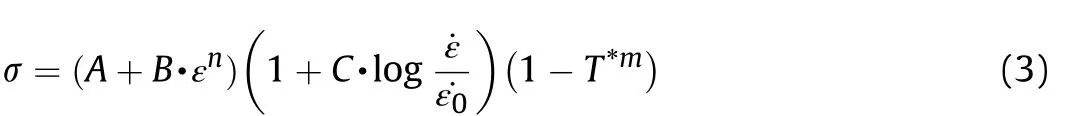
In Eq.(3),,andare the three coefficients that describe thequasi-static behaviour of the material.andreflect the strain rate hardening and thermal softening effects, and ˙εis a user-defined reference strain rate, generally taken as unity.* is the homologous temperature defined using the following equation:
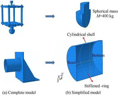
Fig.10.Simplified simulation model in ABAQUS FEM software.
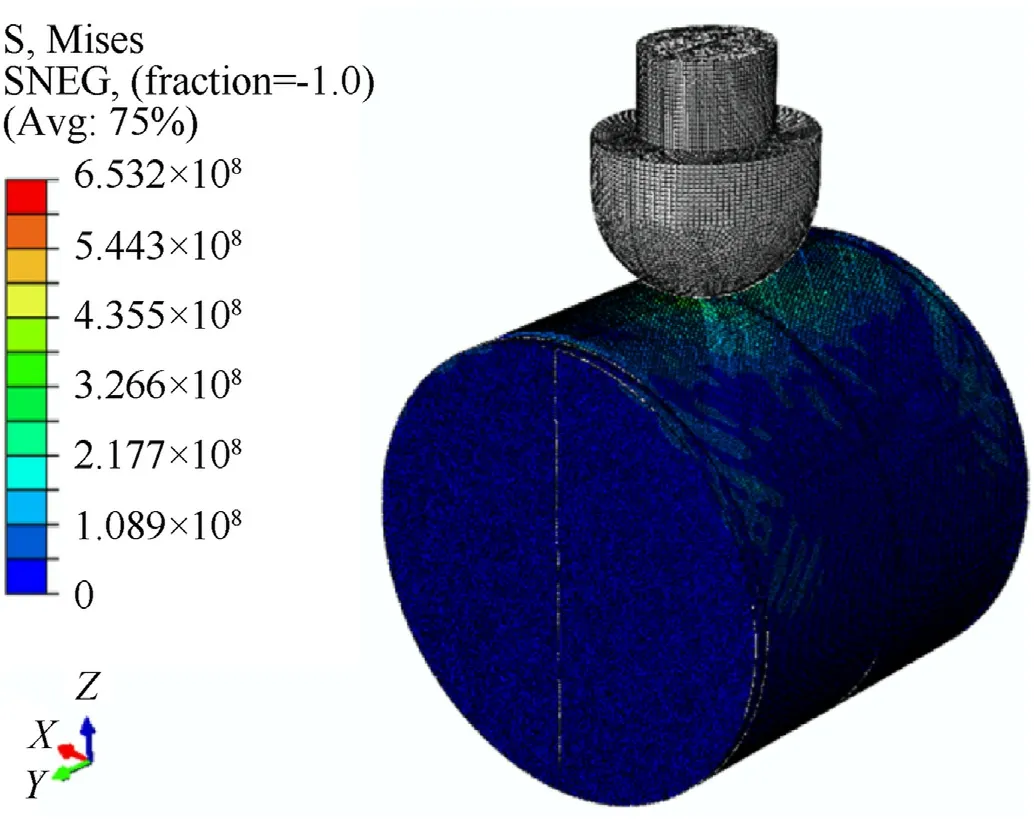
Fig.11.Entire simulation model.
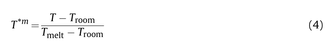
whereis the absolute temperature, andandare the room and absolute melting temperatures,respectively.For the drop test,the effect of*is ignored in Eq.(3).In defining a rigid body,the drop mass material is described using only the elastic constitutive model.
Several simulation research was conducted for different shell thicknessesand stiffened-ring sizes(diameter φ,number of rings) to investigate the structural response of the specimens under various conditions.Typical simulation models using different parameters are shown in Fig.12.
4.2.Material property tests (static and dynamic steel tests)
The Chinese brand of structural steel, Q235, was used as the material for the specimen and stiffened ring.The mechanical properties of the steel were determined through quasi-static tensile tests following the procedures of ASTM E-8M 2004 (Standard Test Methods for Tension Testing of Metallic Materials).Three flat coupons were cut out from their parent cylindrical shell and ring stiffeners,and the coupons were subjected to tests using a universal testing machine (WDW3100).Negligible variations in the yield strength and Young's modulus were observed,and these variations were further reduced by ensuring that all models were fabricated from a single steel sheet.Actual stress-strain curves from the static tensile tests are shown in Fig.13.
In addition, the dynamic properties of the steel sheet were determined in a split-Hopkinson tension bar facility.The related data and curve are depicted in Fig.14.As mentioned in Section 4.1,the objective of these experimental data was to fit the Johnson-Cook equation (Eq.(3)).The mechanical parameters of Johnson-Cook equation were determined and listed in Table 3,and the constitutive model simulation was implemented in ABAQUS .
4.3.Comparison of results between simulation and test
To compare the deformation mode between the test and the Abaqus simulation,models GA-2 and GA-3 after drop mass impact were displayed in Fig.15.Their corresponding deformation maximum values were depicted in Fig.9.
Based on the simulation models shown in Fig.12,the deformed ring-stiffened shell structures were determined (Fig.16).As explained in Section 2, the simulation models received the same drop velocity v(from the same drop height= 4 m).The ringstiffened cylindrical models showed different dynamic responses under the drop mass impact, owing to structural size parameters and total mass.The models with different stiffened rings and shell thicknesses experienced different degrees of deformation and rebound processes.
The simulation models shown in Fig.16(a)and(b)have the same shell thickness and ring size but different numbers of rings.Compared to the model in Fig.16(c), the model structure in Fig.16(d)has the same size of stiffened rings but different thickness sizes.In contrast, the shell thicknesses and ring sizes in both Fig.16(e) and (f) are different.The above comparisons show the dynamic responses with varied shell thicknesses and stiffened rings, subjected to different impact loads.
The simulation results for the related test specimens, i.e.GA2,GA4, and GA5, were plotted, as shown in Figs.17-19, respectively,to compare with the drop test data presented in Fig.9.Each figure includes the impact load and the velocity curves for the drop test or ABAQUS simulations.The simulation curves in ABAQUS showed a similar varied tendency with the test results.Table 4 shows a comparison of the maximum forceand rebound velocity.For maximum force, the relative error of the test results was not higher than 0.1953 (in Specimen GA-4), and the relative error for the rebound velocitywas 0.5686 (only for GA-4).

Table 3Mechanical properties of steel specimen in test.
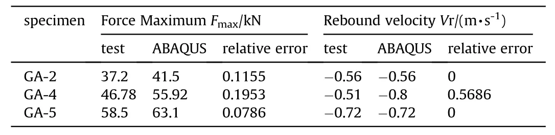
Table 4Result comparison between test and ABAQUS simulation.
The severe damage of the test specimens was evaluated by measuring their final deformation displacements δ.Further attention was paid to the impact regions of the specimens,and the displacement data δ.of the experimental tests and ABAQUS simulations were compared.The experimental displacements δ.of Specimens GA-2, GA-4, and GA-5 were 54, 48, and 68 mm,respectively, and the corresponding results for the ABAQUS simulation were 58,45,and 70 mm(Fig.20).The relative error was not higher than 0.074 (7.4%).
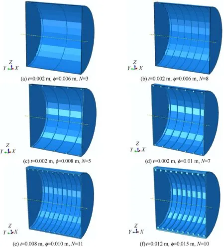
Fig.12.Simulation models with different parameters.
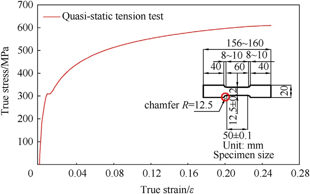
Fig.13.True stress-strain curve from quasi-static tension test.
Moreover,some signals of dynamic strain in GA-2 and GA-5 test models were compared with related Abaqus simulation results in Fig.21.In the test models, strain sensors No.1 and No.2 were displaced near the cylindrical shell's being impacted region.They were composed of two direction signals, horizontal strain and vertical strain.In comparison with the test signals, the simulation results displayed a similar variation in history curves.Although the response time of simulation results is a bit earlier than that of test signals in some figures, the difference of their strain peak value is no more than 9%.Fig.22 displays the comparison of force and displacement in GA test simulation model.Although the response time of simulation results is a bit earlier than that of test signals in some figures,

Fig.14.True stress-strain curve from SHTB test.
A comparison between the test results and ABAQUS simulations showed that the simulation model was suitable for simulating the drop weight impact process (explained in Section 2) in ABAQUS.Additionally, the simulation models and their related material properties were adapted to reflect the dynamic response of stiffened ring shell structures under the drop mass impact.Next, a comparison work was carried based on the above verified models.The simulation conditions are listed in Table 5.
The maximum forceand the displacement δincreased with the drop height in each group.There was a slight difference between Groups 1 and 2 in theand δvalues,except for the data in= 0.72.However, the values in Group 3 were somewhat different.With an increase in the thickness and mass (from 9.8 to 13.3 kg,Table 4),the values ofand δchanged significantly.It could be deduced that the mass change influenced the dynamic response of the stiffened shell structure.The simulations were completed under varied conditions of stiffened-ring structures, as described below, to establish the relationship between, δ,and other parameters.

Table 5Simulation condition of GA test model in ABAQUS simulation.
5.Results and discussion
After contact with the indenter, the compressed region then deformed with a displacement δ along the radial direction of each specimen (Fig.1(b)).The displacement δ showed a linear or nonlinear variation with the impact load, and the deformation area of the specimen was influenced by the stiffened ring inside the cylindrical shell.
It is supposed the relationship between the impact loadand the displacement δ fulfills a nonlinear function as Eq.(5) shows:

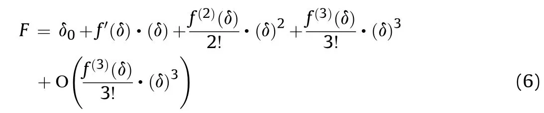
According to the Taylor theory, the function in Eq.(5) can be derived as a polynomial form as:
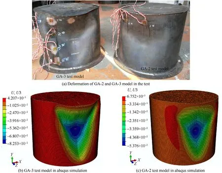
Fig.15.Deformation mode comparison between test models and Abaqus simulation.
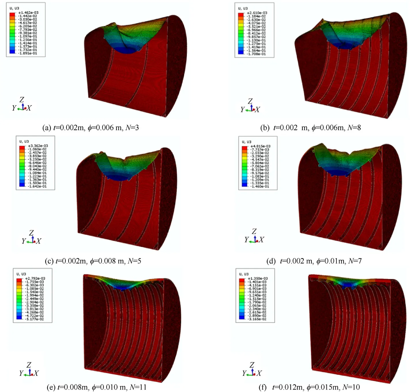
Fig.16.Deformation comparison of ring-stiffened cylindrical shell models.

Fig.17.Comparison of force and velocity in GA2 test model.
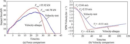
Fig.18.Comparison of force and velocity in GA4 test model.
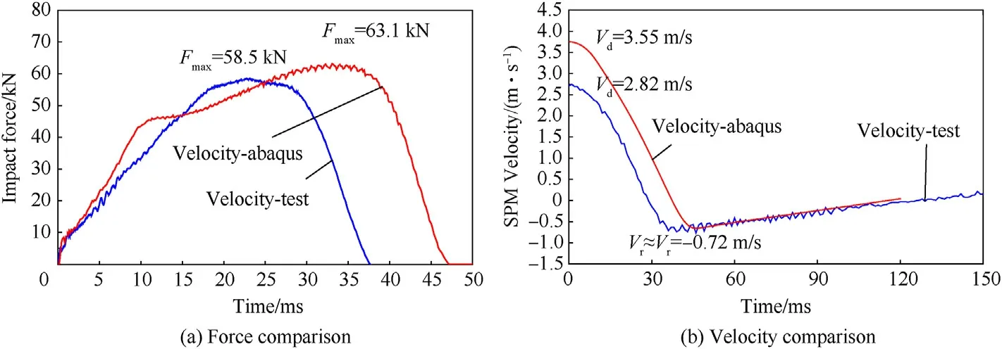
Fig.19.Comparison of force and velocity in GA5 test model.
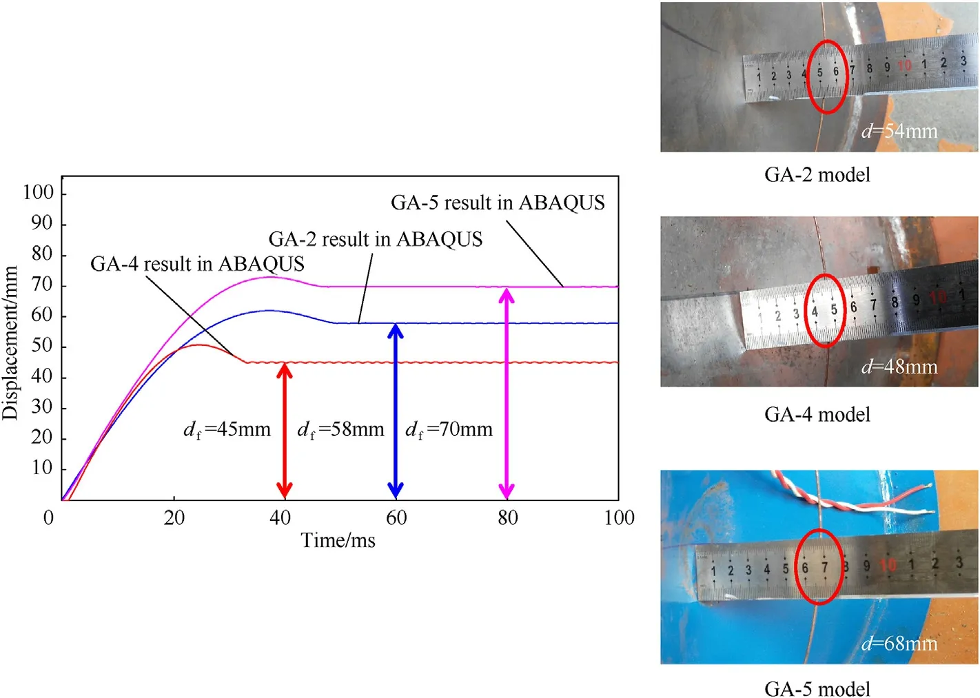
Fig.20.Deformation displacement δf comparison between test and ABAQUS result.
As observed in numerical simulations, the deformation of cylindrical shell is varied with the distribution of inner stiffened-rings with the same shell thickness.To explore the related function in Eq.(5), two conditions are considered as below:
For one aspect, a single cylindrical shell is impacted by the indenter.The cylindrical shell exceeds its elastic limit and forms the yielding area under the impact force.and δare the impact force and compressed deformation of the cylindrical shell,respectively.As described in Ref.[1], a thin plate of depthwas subjected to an indentation by a rigid sphere of radius.If the deformation occurs in the elastic range, the relationship between the impact forceand displacement δis expressed as follows.

For another, the indenter contacts with a cylindrical shell equipped with heavy stiffened rings.In other words, the stiffened rings were strong enough to resist the indenter impact.Under this condition, the analysis of the ring-stiffened shell response was based on the following assumptions:
(a) the stiffened rings are located near the central impact area and collinear with the spherical indenter;
(b) the difference of impact loadingin impact region is ignored;
(c) for stiffened rings, only the deformation along the impact direction δis considered.
In accordance with contact mechanics theory in Ref.[2], if the stiffened rings experienced deformation under the impact, their relationship between the rings and indenter satisfy below equations.
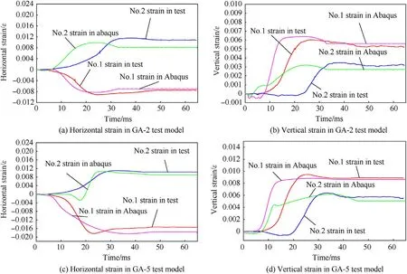
Fig.21.Dynamic strain comparison between test model and Abaqus simulation result.
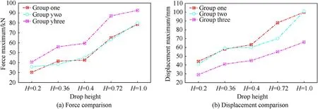
Fig.22.Comparison of force and displacement in GA test simulation model.
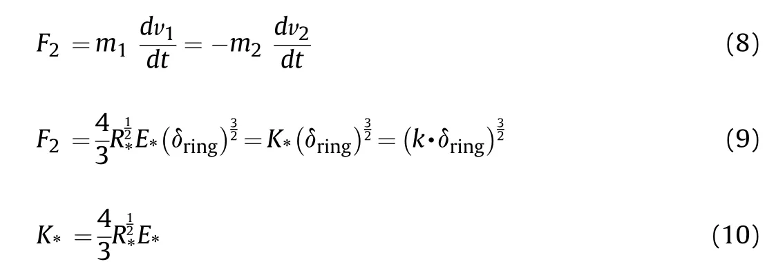

Combined with functions in Eq.(7)and Eq.(9),it is assumed that the impact loadand deformation displacement δ satisfy a polynomial as displayed in Eq.(11)
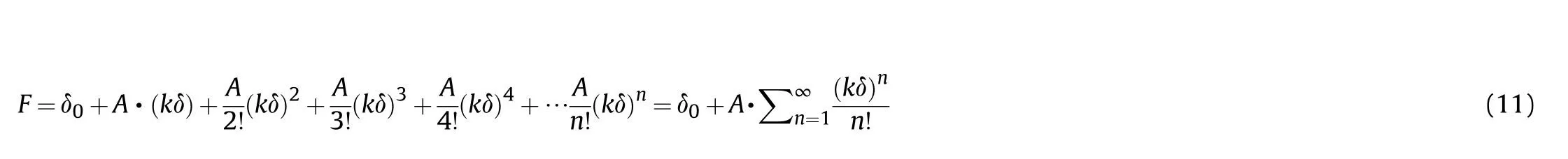
where δis a constant,and,are the related coefficients.Besides,an exponential function can be expressed in the following Taylor's series:
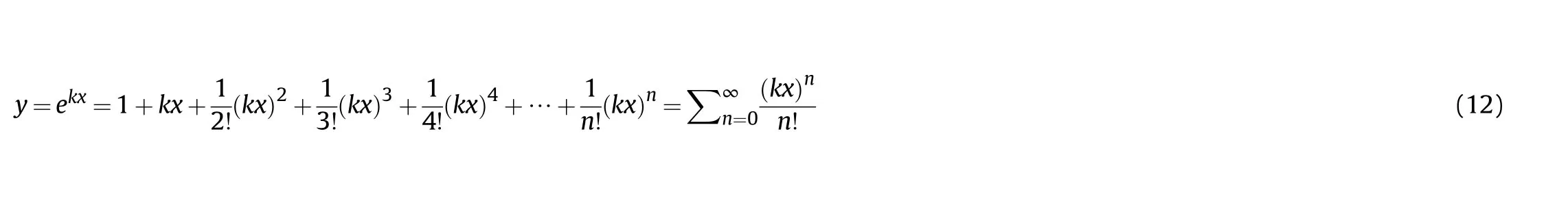
In comparison between Eq.(11) and Eq.(12), it is suppose the related function form between the impact loadand deformation displacement δ can converge in the form of an exponential function.Therefore,Eq.(11)is equal to a convergence form,as expressed in Eq.(13).
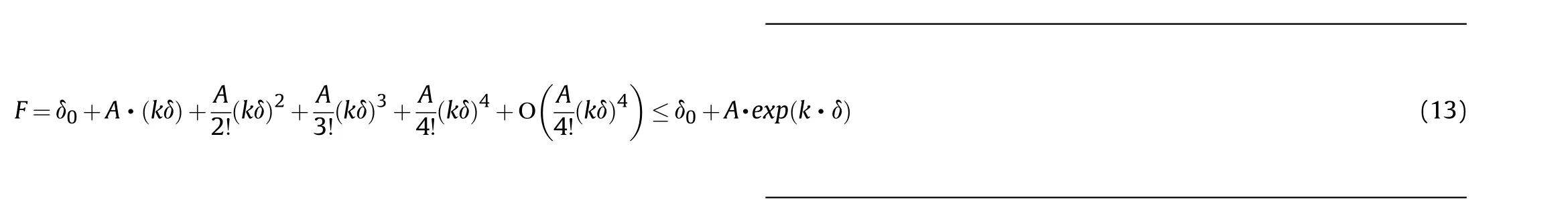

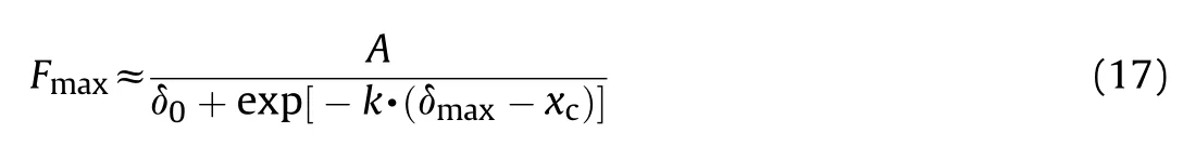
From Eq.(14), the relative expression between the maximum loadand maximum displacement δcan be expressed, as follows.

In addition, the convergence form can be transformed into another exponential function form, as displayed in Eq.(16).
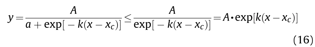
In Eq.(16),,,andare the related coefficients,andis a nonnegative constant value.Similar to the expression form in Eq.(16),another convergence form is achieved.It is also used to describe the relationship between the loadand displacement δ.
As listed in Table 6, the shell thickness and stiffened ring size variations were considered based on the GA test model (as shown in Figs.5 and 6,respectively).The mass contrast ratio ψ and velocity ratiowere defined to describe the correlations in the ABAQUS simulation.The expressions are as follows:
First, further attention was paid to determining the correlation between maximum forceand maximum deformation δwith the variation in the drop height.The simulation models were established based on the size parameters listed in Table 7.They were divided into five groups (Groups GSA-1 to GSA-5) with different mass contrast ratios ψ (see Table 8).
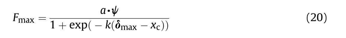
The data for the maximum forceand deformation δare shown in Fig.23.With an increase in the drop height H,the curves showed a non-linear rise.After the relationship curve betweenand δin each simulation group was plotted,each fitting function could be expressed as an exponential function form in Eq.(20).Eq.(20) reflects the relationship betweenand δ.Additionally,ψ.,,andare known as function coefficients and vary with the ratio ψ.
The relationship between the maximum forceand velocity ratiofor each group simulation was established using the exponential function.The known coefficients,,,and,also vary with the ratio ψ, and their values are listed in Table 9.

The ABAQUS simulation results for each group were compared(Fig.24).Fig.24 shows two curves of the spot line and displays the difference between the functions' data and simulation results.Although Eqs.(20)and(21)are derived from Groups GSA-1-GSA-5 data (the size parameters of the GSA models are listed in Table 7),the exponential functions of the simulation model with different ring diameters φ and shell thicknesses(as listed in Table 6) were also fit.The fractional error did not exceed 0.13 (13%).
Variations in ring diameter sizes φ or shell thicknessbring increase or decrease of total mass of the model.It equals to changethe mass contrast ratio ψ.So, another purpose of the simulation work is to find the correlation between parameters δ,and ratio ψ.Based on the ring-stiffened cylindrical shell model with the same thickness and different diameter sizes, the related functions and comparisons are discussed as below.Table 10 lists the parameters of each model in Group GSB.

Table 6Simulation conditions of GA test model.
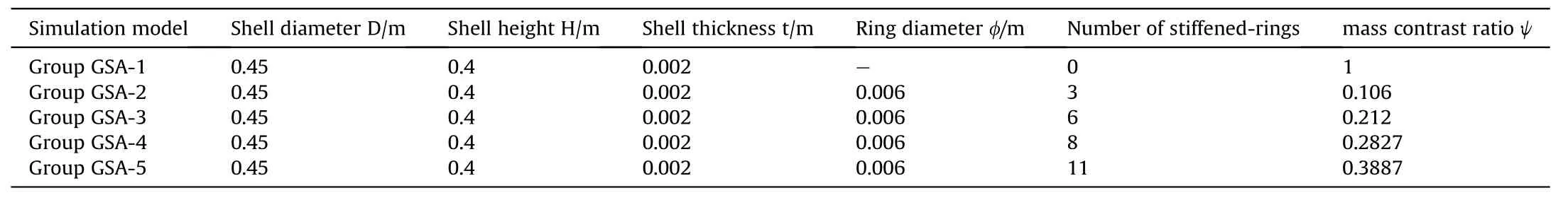
Table 7Size parameter of ABAQUS model in each group.
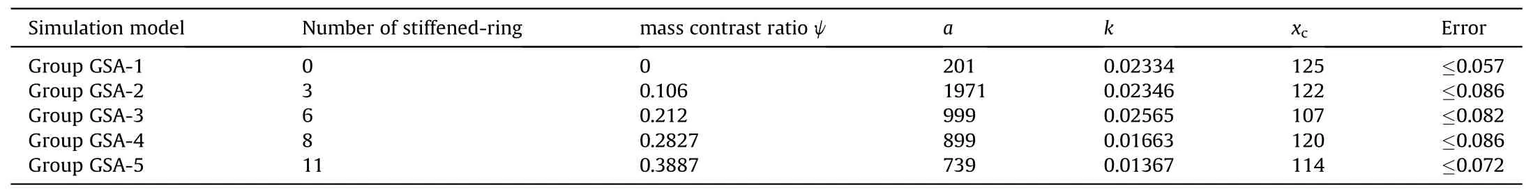
Table 8Coefficients of expression(21) in each simulation model.
Table 9Coefficients of expression(22) in each simulation model.
Table 10Size parameter of ABAQUS model in Group GSB.
Fig.23.Variation of force and displacement maximum in each simulation group.
Fig.24.Variation of force and displacement maximum in each simulation group.
With an increase in ratio ψ,the varied tendencies of δandwere determined, as shown in Figs.25-28.The maximum deformation δalmost declined with an increase in the ratio ψ.The variation of the deformation δcould be described using an exponential function.Furthermore, the relationship between the rebound velocityand mass ratio ψ could be established using a polynomial function.Eqs.(22)and(23)describe the relationship of these two functions with the ratio ψ.
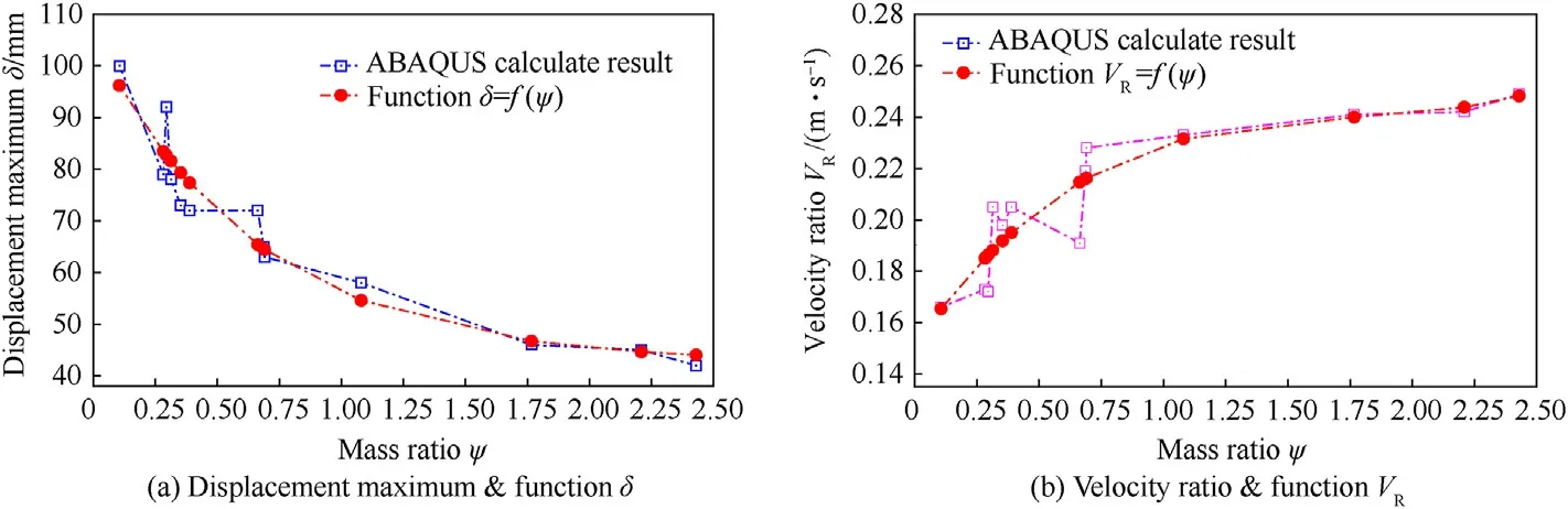
Fig.25.Comparison between parameter and related function in Group GSB-1 (drop height h = 1 m).
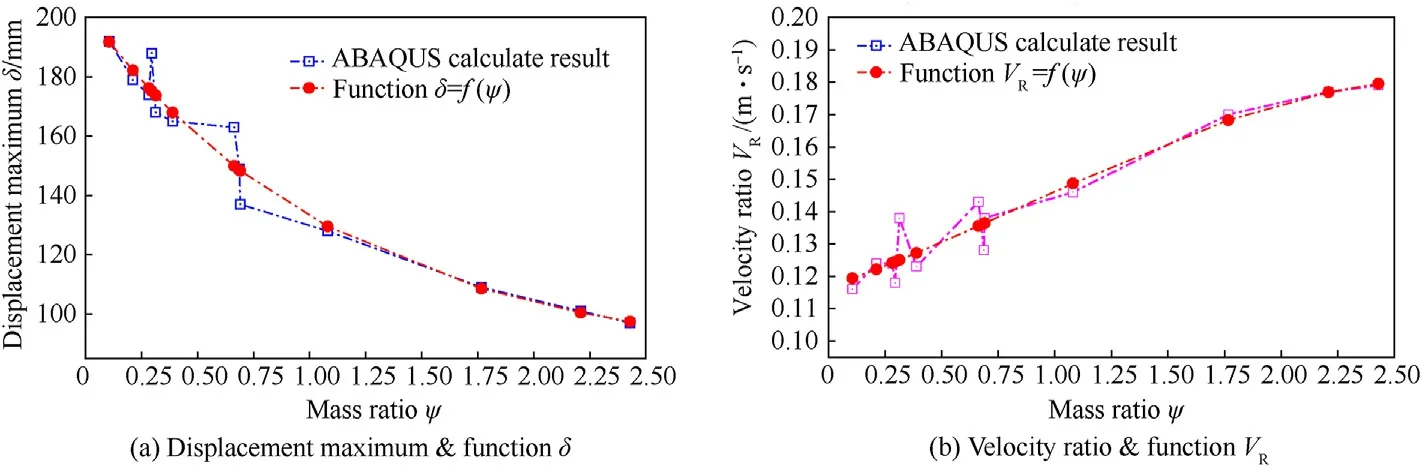
Fig.26.Comparison between parameter and related function in Group GSB-2 (drop height h = 4 m).
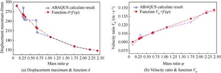
Fig.27.Comparison between parameter and related function in Group GSB-3 (drop height h = 8 m).
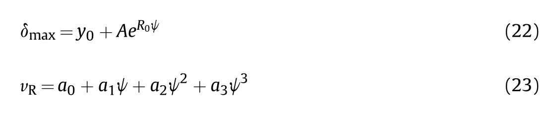
In addition,,,,,,,andare the known coefficients in the equations, and the corresponding values are listed in Table 10.The spot-line of the function results were plotted(Figs.23-26) to reflect the difference between the ABAQUS simulation results and the functions.The relative errors are listed in Table 11.
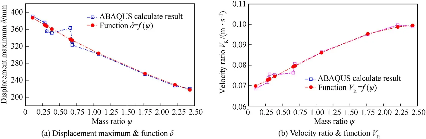
Fig.28.Comparison between parameter and related function in Group GSB-4 (drop height h = 15 m).
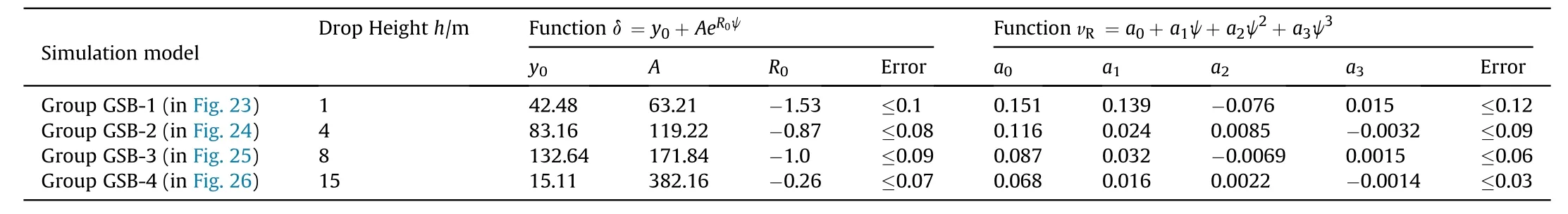
Table 11Coefficients of expression(22) and(23) in each simulation model.
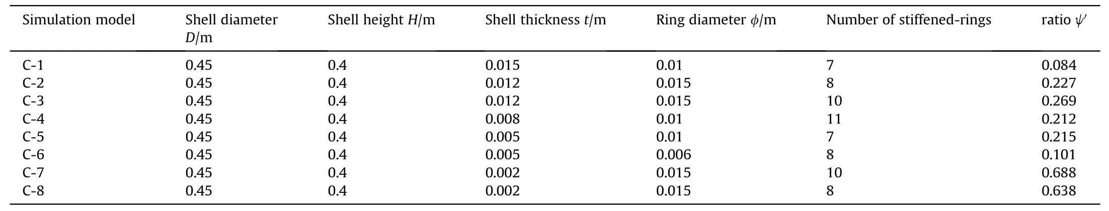
Table 12Size parameter of ABAQUS model in group GSC.
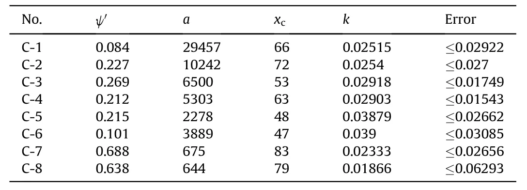
Table 13Function coefficients of each group in expression(25).
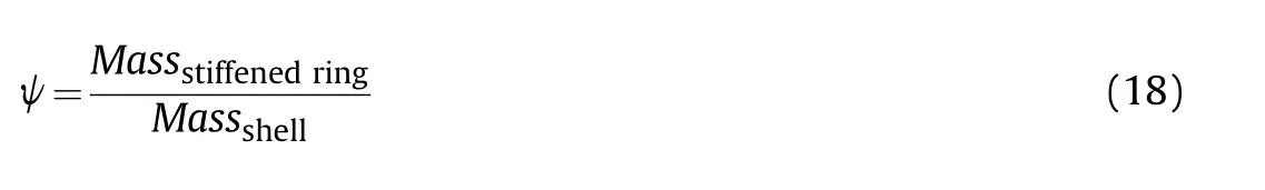
The final purpose of the simulation was to consider the variations in the shell thickness and stiffened rings.Compared to the simulation models in the GSA and GSB groups, the mass of the stiffened-ring structure was significantly influenced by an increase in the thickness.Therefore, another parameter, the stiffened-ring mass ratio ψ, was defined, as expressed in Eq.(24).
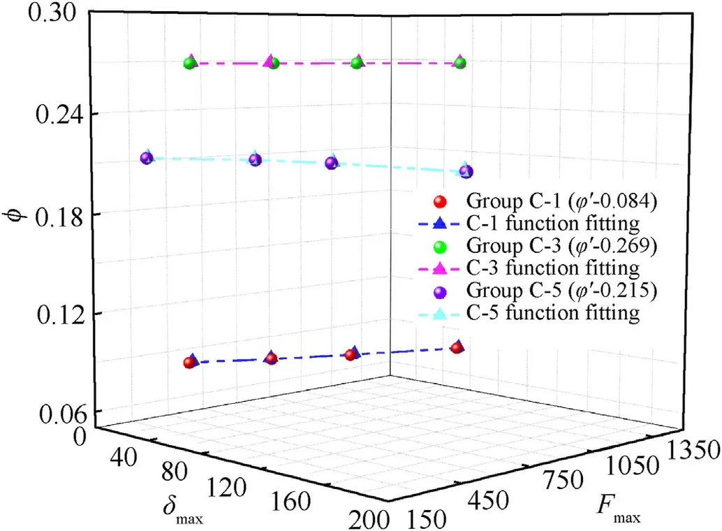
Fig.29.Comparison between simulation results and fitting function for group GSC.
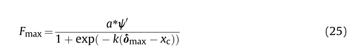
Several models with variations in the shell thickness or stiffened ring size were built in the ABAQUS environment (as listed in Table 6).In this section, the results for eight typical models (from GSC-1 to GSC-8 in Table 12,written as C-1,C-2,and C-8 for brevity)were compared and analysed.The sizes of these models in the GSC group are displayed in Table 12 with the listed stiffened-ring mass ratio ψ '.Similar to the GSA group analysis, a similar function (Eq.(25)) was derived.The derived function could be used to analyse the relationship between the maximum force, maximum displacement δ, and parameter ψ '.
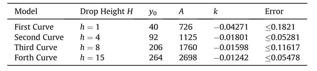
Table 14Function parameters of each group in expression(27).
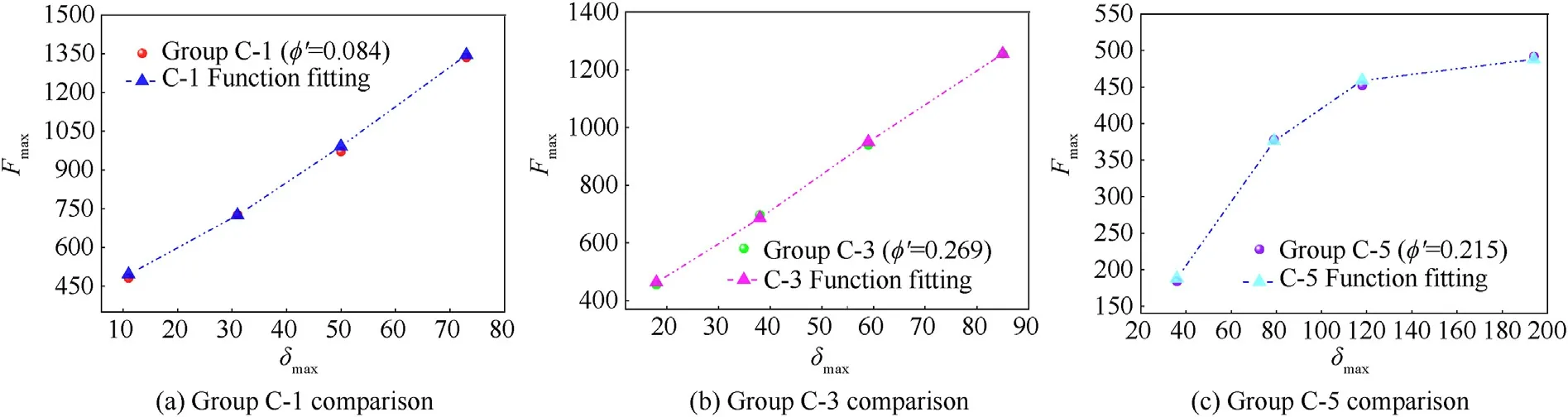
Fig.30.Comparison between simulation and function results in δ-F coordinate.
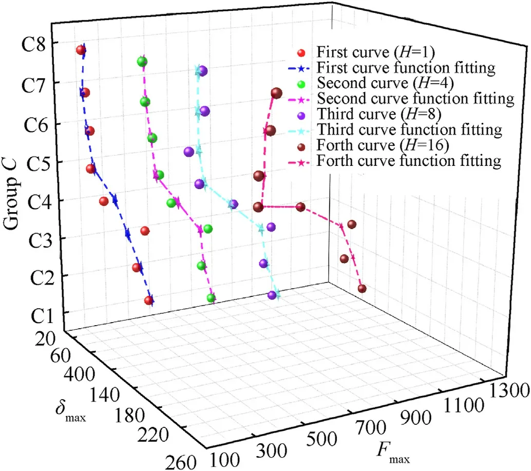
Fig.31.Comparison between simulation results and fitting function for group GSC in spatial coordinate.
In each simulation model, four drop heightswere considered(= 1, 4, 8, and 15), and the related coefficients of the fitting function were determined(Table 13).The fractional error between the simulation and the function value was not higher than 0.06293(6.29%).The fitting function effect was also reflected (Fig.29).As shown in Fig.29, the 3D ball and triangle-dot lines represent the simulation and function value data, respectively, and the vertical coordinate represents the stiffened-ring mass ratio ψ '.For each model,the signals were distributed in the same layer of ψ'=The figures were combined in spatial coordinates (Fig.29) and plane coordinates (Fig.30), and it was observed that the function value showed a good tendency with the ABAQUS simulation data.
Furthermore,the exponential function(26)(similar to Eq.(15))was derived to determine the features of the simulation model data listed in Table 13.Different from the data presented in Fig.31,each non-linear curve and related data were distributed in spatial coordinates(each data for the same non-linear curve corresponded to the model in different ψ).Compared to the simulation data, the tendency of the fitting non-linear function curves indicated the variation in these data.The fractional errors are listed in Table 14,and most errors did not exceed 0.18(18%).Moreover,some features of structural dynamic response can be observed with statistical analysis of impact load-deformation curves-δ.For example,some important information of structural response can be derived by sensitivity analysis as introduced in Ref.[42].

6.Conclusions
The purpose of this study was to investigate the responses of ring-stiffened cylindrical shells subjected to lateral bulk mass impacts.The steel ring-stiffened models were loaded under drop mass impact, and the related simulation models were simulated using ABAQUS.Based on the results of this study, the following conclusions can be drawn.
First, simple fitting functions to analyse the relationship between the maximum loadand maximum displacement δof ring-stiffened cylindrical shell under dynamic mass impact were derived.Based on the validation of the simulation model,the fitting function data were compared with the simulation results, and the fitting functions showed good accuracy.These functions are convenient for predicting the deformation of ring-stiffened cylindrical shell under different drop mass loads.
Second,the mass ratio ψ was proposed to reflect the effect of the mass change in the ring-stiffened cylindrical shell under drop impact.The related exponential or polynomial functions were used to correlate the maximum load,maximum displacement δ,rebound velocity, and parameterψ.
Finally,based on the varied shell thickness and stiffened rings in the cylindrical shell,the stiffened-ring mass ratio ψwas derived to reflect the variation in the structure size.Thus, the exponential fitting functions were determined to predict the relationship between the maximum load, maximum displacement δ, and the mass ratio ψ'.A comparison between the simulation results and fitting function showed good accuracy,and they exhibited a similar tendency in spatial coordinates.This tendency indicates that exponential functions are suitable for describing the relationship between impact loads and deformation for different stiffened cylindrical shell sizes.
The authors declare that they have no known competing financial interests or personal relationships that could have appeared to influence the work reported in this paper.
This work was supported by the National Natural Science Foundation of China (Grant No.51508123, named “Study on blast response of floating roof storage tank in material point method”),and Natural Science Foundation of Heilongjiang Province, China(LH2019A008) to provide fund for conducting experiments and research.The authors would like to acknowledge Professor Wei Wang in Harbin Institute of Technology for instructions and help in experiment design.

- Defence Technology的其它文章
- Study on the influence of armature on the efficiency of reluctance accelerator
- Research on a combinatorial control method for coaxial rotor aircraft based on sliding mode
- An optimization method for passive muzzle arc control devices in augmented railguns
- Numerical and experimental investigation on aluminum 6061-Vgrooved stainless steel 304 explosive cladding
- A capture probability analytic model for the electromagnetic launched anti-torpedo torpedo
- Optimal control based coordinated taxiing path planning and tracking for multiple carrier aircraft on flight deck