Experimental and numerical investigation of zirconium jet performance with different liner shapes design
Tmer Elshenwy ,Qing-ming Li ,Ahmed Eleih
a Technical Research Centre,Cairo,Egypt
b The University of Manchester,School of Mechanical Aerospace and Civil Engineering,Manchester,UK c Military Technical College,Kobry Elkobbah,Cairo,Egypt
Keywords:Shaped charge Zirconium Liner shape Penetration Concrete strength
ABSTRACT This paper studies the shaped charge jet performance in terms of different liner shapes including conical,bell,hemispherical and bi-conical liners.The critical angles and the relevant flow velocities for the zirconium liner material were calculated analytically and numerically using Autodyn hydro-code.The relationship between the critical collapse angle and the flow velocity was determined for the conditions of jet formation and coherency.Penetration tests according to the standard testing procedures of APIRP34 (Section-II) were performed to validate the numerical predictions of the jet performance of the studied liners.It was found that the four shaped charge liners all produced coherent jets with different performances.The penetration depth of the shaped charges with the bell and the bi-conical liner shapes increased by 10.3%and 22%,respectively,while the crater diameter of shaped charge with hemispherical liner increased by 85% representing the formation of an explosively-formed-projectile (EFP),when they are compared with the corresponding jet characteristics of a conical liner shaped charge.
1.Introduction
Oil well perforator(OWP)has been used in oil and gas wells to connect them to the reservoir[1].When the OWP is detonated,the hypervelocity jet can penetrate a large depth into the geological formation media.The velocity and the diameter of the jet depend mainly on the design of the perforator,specially the geometrical shape of the liner that has a direct influence on the collapse angles and velocities of the liner elements.The fully-developed collapse velocity is a function of the metal-explosive mass ratio [2-4].However,a fully-developed collapse velocity can only be achieved when there is sufficient distance between the liner element and jet axis,which may not be available near the apex potion,as shown in Fig.1.Fig.2 depicts the flow velocity (V) in a moving coordinate system with a stagnation velocity (V) and their relationship with the collapse velocity (V).
According to the unsteady state Pugh-Eichelberger-Rostoker(PER) model [5],stagnation (V) and flow (V) velocities can be determined by

respectively.The jet velocity Vis determined by:

where 2α is the cone angle,δ is the deflection angle and β is the collapse angle,as shown in Figs.1 and 2.Based on PER model [5],the deflection angle is given by

where U=U/cosα and Uis the detonation velocity of the explosive charge,which is 8200 m/s for PE4 explosive.
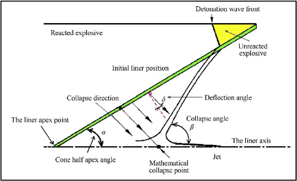
Fig.1. A schematic drawing illustrates the collapse process path from the initial liner position to its axis.
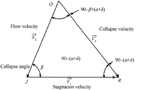
Fig.2. Velocity vectors in a moving coordinate system [5].
The mass of the jet element mhas also a direct relation with the collapse angle according to Ref.[5]:

According to Eq.(2),the jet velocity increases with the increase of Vand the decreases of the collapse and cone angle β and 2α.On the other hand,according to Eq.(4),the jet mass increases with the increase of β.Thus the collapse angle has opposite influences on the jet velocity and jet mass.Furthermore,when β is very small and the flow velocity Vis relatively high,the jet may not form or be coherent even it is formed,according to Ref.[6].Therefore,a combination of Vand β determines the jet formation and coherency for each liner element.The jetting conditions had been studied by many researchers over the past decades.Walsh et al.[7]found that the jetting always happens if the jet material is incompressible or if the collision(flow)velocity(V)in the moving coordinates system is subsonic.Cowan and Holtzman[8]presented an overview for the jetting condition criteria in the explosive welding applications.Chou et al.[6] summarized the jetting and coherence conditions,as shown in Table 1,where βis the criticalcollapse angle for the formation of an attached oblique jet at a given supersonic flow velocity.

Table 1 The condition for the jet formation and jet coherency at different collision velocities and collapse angles [6].
In Table 1 Cis the longitudinal sound speed of the solid liner material given by


Liner shape has significant influence on the shaped charge jet performance.It has been shown that the conical liners with small apex angles produce relatively deep crater with small diameter.On the other hand,the hemispherical liners produce shallow crater with large diameter [1].Various improvements of the liner design have been done in the past fifteen years.For example [11],Zhao et al.[11]and Lee[1]proved that modifying the liner shape design can increase the jet kinetic energy,and hence,the penetration depth.Held [12] used a special flat liner to obtain a superfast jet with jet tip velocity of 25 km/s.Therefore,it is necessary to understand the jet characteristics for different liner shapes and their corresponding penetration performance.
This paper will study the jet formation,coherence and penetration of four commonly-used liner shapes,i.e.conical,hemispherical,trumpet (or bell shape) and bi-conical shapes,in which explosive mass and outer diameter are kept constant.Conical liner will be treated as a reference baseline.The enhanced flow velocities and collapse angles for these zirconium linear shapes are discussed based on the conditions of jet formation and coherence in Table 1.The performance of the formed jets is characterized by their penetration capability into the standard target in comparison with the penetration capability of the conical liner jet.These liners are tested experimentally against the laminated steel-water-steelconcrete standard target according to API-RP43 (Section II) [13].Calculations of jetting,jet formation and penetration of four liner designs are performed using Autodyn hydro-code.
Section 2 gives the conditions of jet formation and coherence for the zirconium liners.Section 3 describes the liner manufacture and the experimental set-up.Section 4 introduces the numerical models,material models and material parameters used to simulate jet formation and penetration of the shaped charges.Results with further analyses are presented in Section 5 followed by conclusions in Section 6.
2.Determination of the critical collapse angle for zirconium jets
It is well known in gas dynamics that,for a flow of free stream velocity Vimpinging on a solid wall,there is a maximum angle β,above which an attached shock wave cannot exist as depicted in Fig.3 [6].The formation of a shaped charge jet obeys the same mechanism [6,7].
Relationships between the critical collapse angle and the flow velocity for some liner materials apart from zirconium have been determined analytically in Ref.[8].The β-Vrelationship is important because it defines the boundary between jetting and no jetting phases on β-Vdomain,as shown in Fig.4.Together with the Climit,three regions can be defined on β-Vdomain,which is explained in Fig.4 for the copper(Cu-Cu)liner with C=4.84 km/s,i.e.(a)Region-I:the region on the left of Climit where coherent jet is formed;(b) Region-II:the region on the right of Climit and above the β-Vcurve where non-coherent jet is formed;(c)Region-III:the region on the right of Climit and below the β-Vcurve where jet cannot be formed.Two methods will be used in this paper to calculate the critical collapse angles at a given flow velocity.
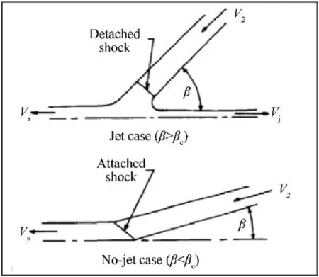
Fig.3. The flow configurations in the supersonic regimes with attached and detached shocks [6].
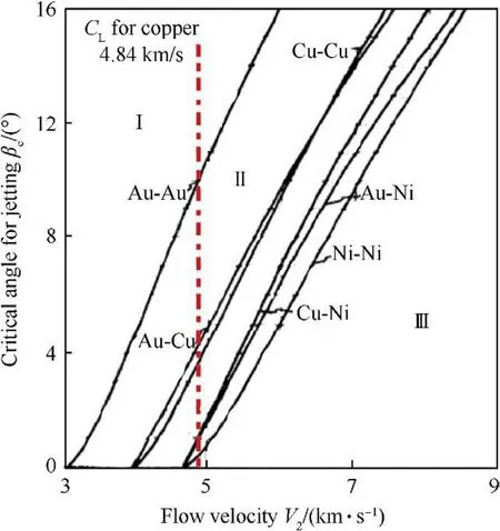
Fig.4. The calculated critical angles for different liner materials at different flow velocities [8].
2.1.Method 1
The analytical model in Ref.[7,8] employed the momentum balance to obtain the critical collapse angle.According to Ref.[7],the critical collapse angle is given by

where P is the pressure,ρis the initial liner density and μ is the compressibility (i.e.μ=ρ/ρ-1).
The maximum angle can be determined for a given impinging velocity Vfrom the condition dβ/dμ=0 [7].Thus,for β=β

Eq.(7) together with the equation of state (EOS) of the liner material can be used to calculate the critical angles βat different values of V.Shock EOS takes the form of [14]:

where Cis the sound speed of the liner material and S is the slope of the shock speed-particle velocity line.For zirconium,C=3757 m/s and S=1.018 [14].
Differentiating Eq.(8) with respect to μ gives

For simplicity,S ≈1 is assumed,and therefore,Eq.(9)is reduced to

The critical compressibility (i.e.μ) and the corresponding critical pressure Pcan be obtained from Eqs.(7),(8) and (10).Therefore,βcan be determined from Eq.(6).The detailed calculation procedures are presented in Appendix C.
2.2.Method 2
The Second method used Autodyn hydro-code with Euler solver to calculate the β-Vcurve based on a model of liner material impinging to its axis of symmetry,as shown in Fig.4.The jet formation has been validated in Refs.[15,16],where the features of the jet predicted by the Autodyn hydro-code were validated experimentally using the flash x-ray and with numerical methods.The problem was approximated by a transient oblique impact model under proper initial conditions with the assumption of a steadystate flow configuration.The model is described as a zirconium liner of wall thickness 2 mm moving towards its axis at a uniform constant velocity Vimpacting a rigid boundary at constant angle β,as depicted in Fig.5.The rigid boundary is the symmetrical axis of the axisymmetric 2D model [6] and the initial pressure in the material is zero.Various combinations of flow velocities and collapse angles were used to cover all three regimes,i.e.subsonic coherent jetting,supersonic non-coherent jetting,and supersonic non-jetting.These calculations were performed for the axisymmetric Euler configurations and the jetting and non-jetting phenomena were inspected against their corresponding criteria.The tested flow velocities were 3,4,5,6,7 and 8 km/s,while the tested collapse angles were 2.5,5,7.5,10,12,15,17 and 20.The β-Vcurve obtained for the zirconium metal liner can be used to design the liner shape for the formation of a coherent jet.
According to Eqs.(1b) and (3) and the jet formation condition V≤C,we have

where βis the theoretical critical collapse angle(i.e.the minimum collapse angle) for the formation of a coherent jet.
For zirconium liner material,C=4566 m/s,U=U/cosα with U=8200 m/s and α=23.Therefore,for PE4 explosive,Eq.(11)can be rewritten as
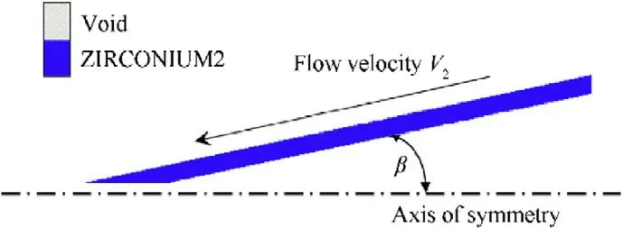
Fig.5. The flow configuration in Autodyn 2-D model used to estimate the critical angle of jetting.

On the other hand the β-Vcurve can be calculated based on analytical or numerical methods introduced before,which together with Eq.(1b)can define another critical collapse angle as a function of collapse velocity V.As an example,we used the numerical method (i.e.Method-2) to calculate values of (β,V) for the zirconium liner,which can be used to fit a β-Vcurve,i.e.

Substitution the value of the Vfrom Eq.(1) into Eq.(13) gives

Solving quadratic Eq.(14)for the positive values of β(0<β<π)gives
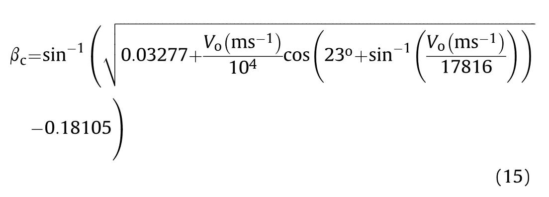
Plotting Eqs.(12) and (15) for different values of collapse velocity V,three regions were defined in Fig.6,which can be compared with those corresponding regions in Fig.4.The advantage of Fig.6 is that it can be used to check the jet formation and coherence directly from the jet collapse velocity V,which can be determined by the liner-explosive mass ratio and the detonation velocity of the explosive,without requiring further calculations for the flow velocities.
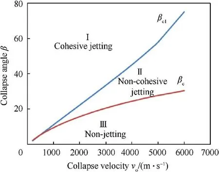
Fig.6. The relations of the theoretical minimum coherent critical angle βc1 and critical angle βc for the zirconium liner at different collapse velocities.
3.Experiments
Amongst different tested liner materials,zirconium exhibited the longest cumulative jet length and the highest ductility factor,which is a necessity to sustain longer breakup time and to achieve larger penetration depth [17].In this study,the zirconium liners were manufactured by high precision CNC machine (i.e.the precision of 10 μm).The raw material was a solid cylinder of pure zirconium 4 N(99.9951)having a diameter of 46.17 mm and a length of 99.89 mm with a density of 6623 kg/m.The impurity percentages of the zirconium material are listed in Table 2.The zirconium rod was annealed to 900C for 1 h before machining in order to obtain a relative small average grain size,hence to increase its ductility,which in turn increases its breakup time and improve the liner performance[18].The raw material of the Zirconium rod and the manufactured liners are illustrated in Fig.7.
The zirconium material has two problems with its machining.The first one is related to its high tendency to work hardening during machining,while the second one is the possible ignition of the fine chips that accumulate near the machining equipment[19].To avoid these problems,slow speed and heavy feed were applied with a continuous coolant supply of water soluble oil lubricant to reduce temperature and prevent flammability of the fine chips.
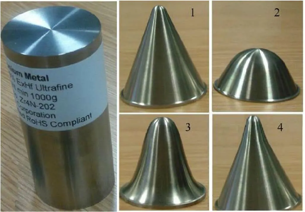
Fig.7. The zirconium solid cylinder (left) and the manufactured liners;1:conical;2:hemispherical;3:bell;4:bi-conical shape.
The PE4 explosive was used with the four shaped charges.PE4 is a RDX-based powerful explosive(i.e.mass composition of 88%RDX and 12% plasticizer and other additives) having a detonation velocity of 8027 m/s at 1590 kg/mdensity [20] and 8200 m/s at1600 kg/mdensity [21].The assembly and set-up procedures include:(i) fill PE4 into the steel casing;(ii) press the liner slowly against the steel casings containing high explosives to expel air gaps inside the perforator charge;(iii)attach the shaped charge to the upper steel layer of the test configuration in Fig.8.

Table 2 The elemental percentage of impurities in the Zirconium material.
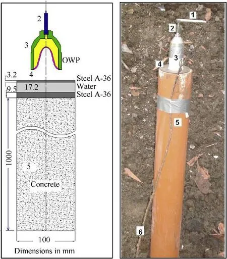
Fig.8. Dimensions of the test setup and the experimental test configuration.(1:Detonator;2:Booster;3:OWP;4:Front steel disc;5:Concrete;6:Power supply).
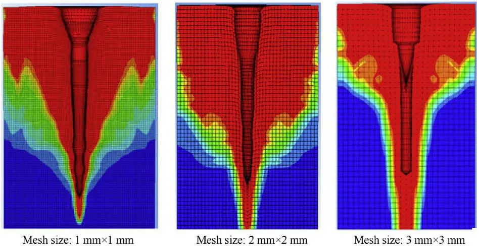
Fig.9. The impact area of the jet-test layers modeled by jet solvers using three different mesh sizes.
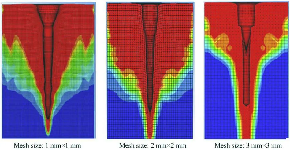
Fig.10. The damage contours near the impact surface for the three mesh sizes at 40 μs.
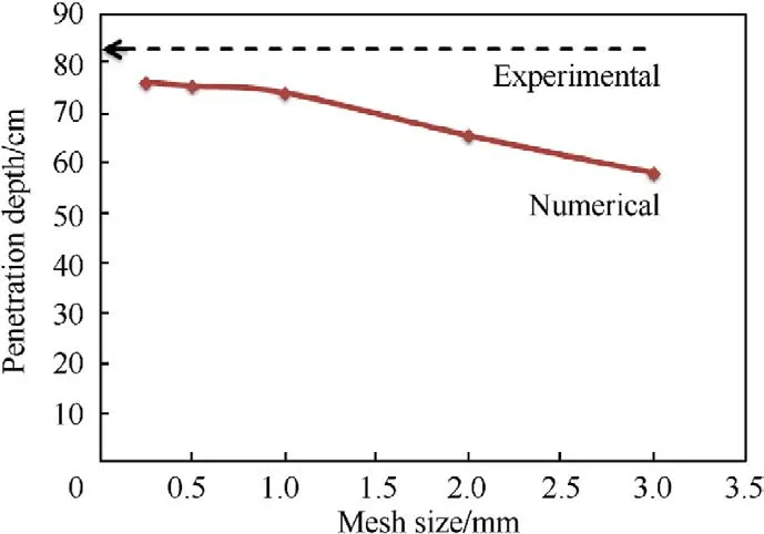
Fig.11. The Numerical penetration using different mesh sizes and experimental penetration.
The concrete cylinders with the designated strength were casted in 1 mm wall thickness PVC tubes and allowed to cure according to the test evaluation of the well perforator [22].These concrete targets were tested according to the standard OWP testing configuration and requirements in the Section-II of API-RP43 [13].The measured average strength of the standard concrete cubes was 40.02 MPa with a standard deviation of 0.92 MPa,measured at 28 days from their pouring [23].
4.Numerical models
A general description of the Autodyn algorithms used in this study is explained in Appendix A while a general description of the material models used in numerical modelling is given in Appendix B.Mesh sensitivity analysis is briefly presented below for a biconical liner,as an example.
In our jet formation analysis,which is not presented in this paper,it has been shown that the Lagrangian bi-conical jet meshes of 0.5 mm × 0.5 mm is sufficiently small to accurately model the shaped charge jet(i.e.the difference between the jet tip velocity in each numerical models (0.25 mm and 0.5 mm meshes) is only 0.16%,which can be neglected).In order to study the mesh sensitivity on the jet penetration,five different mesh densities of 0.25,0.5,1,2 and 3 mm were proposed for the concrete target.Fig.9 shows a sample of three different mesh sizes in the impact area,while Fig.10 shows the concrete damage contours relevant to these meshes at 40μs from the moment of impact.It can be observed that the damaged areas for the three mesh sizes are similar,but the crater profiles indicate the main difference in the crater shape due to the different mesh densities.
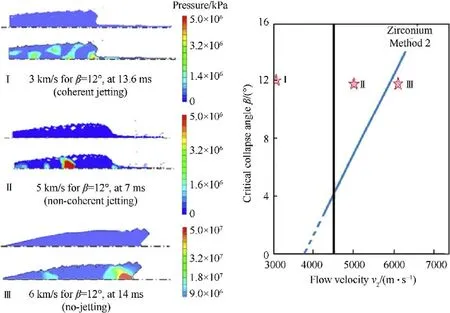
Fig.12. Left:the cross-sections of the collapsed zirconium jet impacting on the symmetrical axis at collapse angle of 12° and flow velocities of 3,5 and 6 km/s for cases I,II and III,respectively;Right:the regions on the βc-V2 curve.
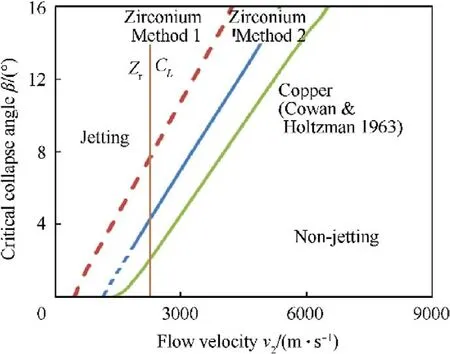
Fig.13. The analytical and numerical βc-V2 curves for zirconium liner with the numerical βc-V2 curve for copper liner as reference.
All five simulations models with different mesh sizes were allowed to proceed until the final penetrations were achieved and the crater profiles were characterized.This happens either when the jet is completely consumed or eroded or when the jet reduces its velocity below a critical value,where the jet loses its penetration capability.The total penetration depth for the five mesh sizes is depicted in Fig.11.
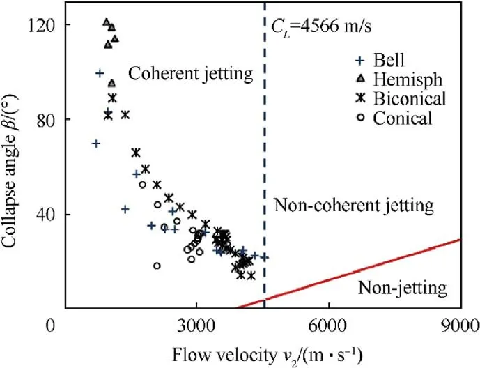
Fig.14. β and V2 values for four zirconium liner shapes from jetting analysis,in which different regions of zirconium jet formation and coherency are shown.
There is a large difference of the penetration depths for coarse and fine meshes between 1 mm and 3 mm indicating the sensitivity of the penetration depth to the mesh size.However,when mesh size is smaller than 1 mm,this sensitivity is largely reduced,and the penetration depth approaches to an asymptote.According to Fig.11,the predicted penetration depth using 1 mm mesh size is 2.75%different form that of 0.25 mm mesh size while the latter model costs five times more than the computational time of the 1 mm size model.Thus,it was decided to use 1 mm concrete mesh size for the rest of modelling to maintain reasonable computation accuracy and time.
5.Results
5.1.The βc-V2 calculations
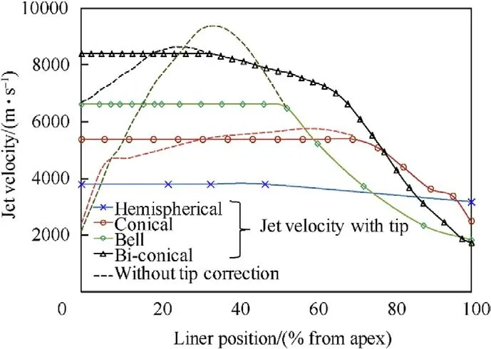
Fig.15. Jet velocity profile along the liner axis with and without tip correction.
For zirconium material,C=3757 m/s and ν=0.34.Therefore,the longitudinal sound speed of the zirconium material is C=4566 m/s according to Eq.(5).Three cases with fixed collapse angle of 12and different flow velocities,i.e.Case(I):V=3.0 km/s,Case(II):V=5.0 km/s and Case(III):V=6.0 km/s,were modeled using Autodyn hydro-code for the model shown in Fig.5.According to Table 1,Cases (I)-(III) belong to coherent jetting,non-coherent jetting and non-jetting situations,respectively.Fig.12 shows the cross-sections of the collapsed jet impacting on the symmetrical axis for these three cases,in which,jetting [Cases (I) and (II)] and non-jetting[Case(III)]cases can be easily identified as depicted by the right images in Fig.12.The jet in Case(II)has a large number of radially-dispersed particles representing a non-coherent jet.
The analytical and numerical β-Vcurves for zirconium liner are shown in Fig.13 where the numerical β-Vcurve for copper liner was also included as a reference.This figure illustrates the boundary between jetting and non-jetting and the boundary between coherent jetting and non-coherent jetting cases.When Vand β are calculated from jetting analysis,this figure could be used to determine the jetting formation and coherency in the design of zirconium liner.
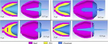
Fig.16. The jet shapes for the different liner geometries right before the impact on the target.

Table 3 Four liner shapes and their jet characteristics.
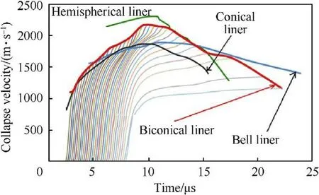
Fig.17. The collapse velocity histories for four different liners.
The β and Vvalues were obtained for four zirconium liner shapes from jetting analysis,which are shown in Fig.14.This figure confirms that the four liner designs can produce coherent jets and indicates the abnormal high collapse angles for the hemispherical liner,which helps the formation of massive explosive-formedprojectile (EFP) rather than the traditional thin jet.This can be explained by Eq.(4) where the jet mass is directly proportional to the collapse angle.The performed jetting analysis showed that the EFP mass is massive 68% of the total mass of its liner.
5.2.Jet characteristics of different liner shapes
The jetting analysis calculates the jet characteristics until the liner elements reach their axis to form a jet element.Thus,it does not consider the jet elongation and the breakup time resulting from this elongation[24].In addition,the jet tip velocity correction is not included,which is necessary because the points near the apex region do not have sufficient space to accelerate to its theoretical maximum collapse velocity,resulting in a reduced tip jet velocity and pilling up of the jet mass[4].Thus,the inverse velocity gradient needs to be removed by adding the piled-up mass to the jetting element with the highest velocity.Then,the jet tip velocity is corrected based on the momentum conversation.The corrected jet tip velocity was calculated according to Ref.[25]:
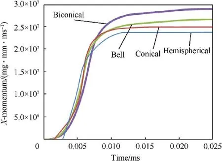
Fig.18. The X-momentum histories for the four perforators with different liner shapes.

Table 4 The numerical and experimental penetration depths using different liner shapes.
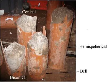
Fig.19. The experimental penetration depths for the zirconium liners according to testing procedures of API-RP43 -Section-II.

Fig.15 shows the jet velocities as a function of the distance from the apex with and without correction.In this figure,the liner with the bell shape was predicted by the jetting analysis to give the highest tip velocity exceeding 9 km/s.However,after the tip correction,the tip velocity is reduced to 6.63 km/s.The pilled-up tip mass of the bell-shape liner is illustrated in Fig.16,which can be compared with the characteristics of the jet mass generated from other three liner shapes.On the other hand,the bi-conical liner shows less difference between the theoretical and the corrected tip velocities,which are 8.6 and 8.4 km/s,respectively.The hemispherical liner produces explosive-formed-projectile (EFP) rather than the thin jet.As shown in Fig.16,most of the hemispherical liner mass flows to form EFP with the largest diameter and mass,but with the slowest velocity (3.8 km/s).Therefore,the crater diameter in the concrete target produced by EFP is expected to be the largest one amongst the four liner shapes.
The collapse velocity can be fully developed either by allowing sufficient acceleration distance between the liner elements and the symmetrical axis of the shaped charge(e.g.the bell shape liner)or by using a reduced cone apex angles (e.g.the bi-conical liner).Actually,both factors are applicable to the jet formation of bell shaped liner because,in addition to the increased liner distance from its axis,the bell shaped liner close to the base has a small angle,which increases the jet velocity according to the unsteady PER theory[5].Fig.17 illustrates the collapse velocity-time histories for the studied four liner shapes.The hemispherical liner apex angle decreases gradually from the apex to the liner base,and the minimum angle (α) of the hemispherical liner is 29,which is responsible for the reduced achievable jet velocity.However,the collapse velocity of the hemispherical liner is considered to be the highest among the four liner shapes in the apex region up to 40%of liner position from the apex.This is due to the existence of sufficient space available for its liner elements in the apex region to accelerate.The jetting analysis indicated that the collapse angles of the hemispherical liner ranging from 95 to 120are greater than those of the other liner shapes,which lead to the greatest percentage of the jet mass from the total liner mass (i.e.67.57%) according to Eq.(4).
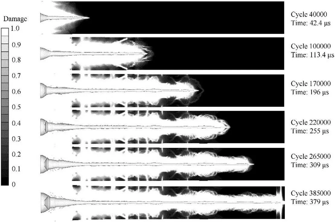
Fig.20. The damage contours of the concrete penetrated by the bi-conical jet at different times.
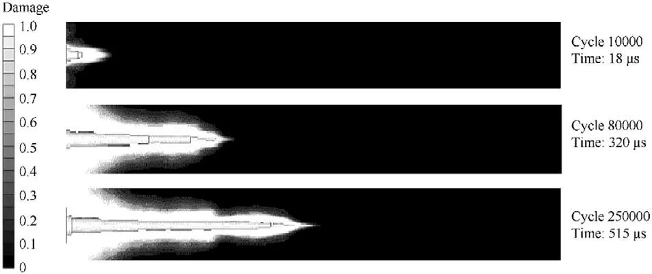
Fig.21. The damage contours of the concrete penetrated by the hemispherical EFP at different times.
The collapse velocities for both the conical and the bi-conical liners are similar in the region near the liner apex because they have nearly the same inclination angle at that region and only have small difference between their explosive-metal mass ratios.Beyond this region,their collapse velocity difference begins to increase because the bi-conical liner has smaller liner angle,which enhance the explosive-metal mass ratio due to the change of geometry.The bell shape liner,which has a long distance between its inner surface and the axisymmetric axis of the shaped charge,gains more collapse velocity than both the conical liner near the apex and the bi-conical liner at the liner base.Since the tip velocity of the jet is produced from the liner elements near the apex,the bi-conical liner has the largest jet tip velocity.In addition to the above-discussed factors of the liner shape,another important factor for the remarkable difference of the collapse velocities is the liner surface area that determines the transmission of explosive energy to the liner.According to Table 3,the surface area of the bell and the biconical liners are 7% and 25% greater than that of the conical one,respectively,which means that both these shapes are capable of absorbing more energy from the explosive although they have nearly the same total mass ratio between the explosive charge and the metallic liner.The transmitted momentums are shown in Fig.18 where the X-momentum-time histories of the four liner shapes exhibit a similar exponential relation.However,the difference between them accounts for the difference in their jet velocities and explains why the liners with a greater surface area have a better performance than those with lower surface area.
5.3.Penetration
The numerical predictions of the penetration depth into 40 MPa concrete target for the four perforators with different liner shapes are presented in Table 4,together with their corresponding experimental penetration depths shown in Fig.19 for the remaining penetration after its damage.Unfortunately,the damaged area around the crater profile confirmed by the numerical calculations shows no experimental measurement of crater diameter.Samples of the numerical penetration stages of the biconical jet and hemispherical EFP,as two examples representing very different shaped charges,into concrete are illustrated in Fig.20 and Fig.21,respectively.The difference between their crater profiles is significant.The shortest penetration path with the biggest crater diameter of the hemispherical liner is a typical characteristic of EFP,which has a short length,a large diameter and a very low tip velocity,as shown in Fig.16,in comparison with the other jets.On the other hand the produced jet from the bi-conical liner has a small jet diameter and a high tip velocity,therefore its kinetic energy per unit area of the jet cross-section is considered the greatest one,and hence its penetration depth is the largest one in comparison with the other three liner designs.
Although the current research is assigned to study and assess the enhancement of the penetration depth of some shaped charges used as OWP in the field industry,but based on the initial liner shapes design,several conclusions can be drawn for further applications.The traditional baseline conical liner is not considered as the optimum performance one,but it is still used because of the simplicity of its manufacturing techniques (as spinning or deep drawing).It can be used as an OWP with moderate performance and also used as a shaped charge liner in bombes as in cargo ammunition.The hemispherical liner exhibits the largest crater diameter due to its massive EFP slug.This can either be used as a thermobaric precursor charge as a military anti-tank application or can be used against submarines due to its shallow penetration but with a wide crater.The bell and the biconical shapes have a relative similar penetration depth due to their higher tip velocities and relative kinetic energies.The Biconical liner is considered as the optimum design when a larger penetration depth is required regardless the crater diameter size as in some warhead missiles.Also,it can be used as an OWP in enhanced perforating gun.
Table 4 shows also a significant variation between the exit hole diameter accompanied with the four liners.This phenomenon is mainly attributed to the shape of the generated slug,which is responsible for the shape of the generated crater.The largest exit hole diameter is achieved with the hemispherical liner due to its EFP slug shape.In addition,this hole diameter may be wider if the copper liner is used instead of the current zirconium one because the zirconium is more ductile than copper,which may cause more elongation when the stand-off distance is increased.This leads to more elongated but less wide slug profile in our case of zirconium liner.On the other hand,the more directed jet having the largest ductile stream,the biconical liner exhibits the lowest crater diameter when compared to the EFP hemispherical one.
The penetration depth of the OWP into the concrete material reflects the importance of the liner shape design on the performance of these perforators.Thus,the larger the penetration depth into the concrete,the greater the flow productivity of the well and the better the performance of the OWP.
6.Conclusions
The critical collapse angle as a function of flow velocity was calculated numerically and analytically for the zirconium liner material in this paper,which,together with the longitudinal sound velocity of the liner material,defines the boundaries among jetting,coherent jetting and non-jetting situations.The regions divided by these boundaries were used to exam the jet characteristics of four zirconium OWP liners with different shapes.It was shown that the jets of four different liners are coherent,but have different collapse,flow and jet velocities because of their different geometries and surface areas.The enhanced performance of the liner shape effect was confirmed by the static firing of four zirconium OWPs against the laminated API-RP43 targets.The bi-conical liner exhibited the largest penetration depth into target,which is 22%greater than that of the baseline conical zirconium liner.The large collapse angles in the hemispherical shape increased its jet mass,but decreased its velocity,and therefore,it is classified as an explosively-formedprojectile (EFP) featured by a massive mass slug.An EFP achieves the shortest penetration depth,but largest crater diameter among the four OWPs of different liner shapes.
The authors declare that there are no conflicts of interest regarding the publication of this paper.
The charge filling and field tests were carried out in the Event Horizon Ltd,UK.
Autodyn hydro-code is based on mass,momentum and energy conservation equations where the materials can be defined by its equation of state and its strength model[14].Three numerical tools,i.e.shaped charge jetting analysis,jet formation and jet penetration,are used in this study,which are briefly described below.
The jetting analysis:The jetting analysis in Autodyn was validated for a shaped charge of 90 mm liner diameter and a cone angle of 18against experimental results and other analytical models(i.e.HEMP and PISCES) [24].The jetting analysis that is based on both the analytical unsteady PER theory [5] and the numerical finite difference technique is used to calculate the jet and the slug velocities and masses as well as the collapse and the deflection angles of the liner elements.In this algorithm,the liner is described as a thin shell composed of a series of nodes having the real thickness of the liner,while its apex point is fixed by a boundary condition to prevent its motion [24].An interaction between the Lagrangian shell liner and the Euler explosive and charge casing is defined by Euler-Lagrange polygon surface.The jetting points are defined for all the liner nodes except the first one fixed by the boundary condition.Once the jetting is completed,the jetting summary including the angles,the velocities and the masses of all the liner elements will be obtained.The jetting option uses a combined numerical and analytical approach.For the first approach,the hydrodynamic equations of motion are used to compute the initial collapse velocity that will be used in conjunction with the second approach to obtain the jet and slug masses and associated velocities using the nonsteady state PER theory.
The jet formation is simulated using Euler method based on continuum mechanics to obtain the jet profiles at different time stages.In this scheme,the explosive,the charge casing and the liner materials are filled into the global Euler multi-material part [14].This processor is suitable in the early jet formation stages,where large distortions will be caused by extremely high strain-rate in the order of 10s[26,27].These distortions will cause the solver to stop working if a Lagrange solver is used for the jet formation.The Euler multi-material processor describes the detonation wave propagation inside the charge and the jet structure as it elongates with time.The jet is allowed to move on the Euler grids up to the moment when it impacts the target,at which the formed jet should be remapped into a Lagrangian jet having non-uniform velocity distribution.The output of jet formation scheme will be used as the input of jet penetration scheme.
The jet interaction (penetration) with the laminated target layers is simulated using Lagrange method.In this scheme,the jet obtained from the jet formation Euler solver is remapped to Lagrange moving grids and impacts the multilayered target.To overcome the mesh distortion problem in Lagrange solver,a mesh discard option or erosion strain is applied to the jet and the target materials.The erosion strain does not represent a physical phenomenon,but a numerical algorithm to prevent the mesh distortions[28].Erosion strains of 200%and 600%were used for concrete and copper liner materials,respectively,according to Ref.[28],in which the same EOS and strength models for the concrete and copper liner as those used in this paper were employed and the numerical model was validated.In a separate work,Marinko [15]studied the effect of erosion strain on the penetration depth for shaped charge jet penetration where the optimal erosion strain was found to be 300% for concrete for good agreement between numerical and experimental results.For the consistency of materials and material models,this study will use the erosion strain values recommended in Ref.[28],i.e.200%and 600%for concrete and liner material,respectively.
In jet formation and jet penetration simulations,suitable material models and parameters have been established in Autodyn,which are briefly described in this appendix.
The equation of state (EOS) for the high explosive is “Jones-Wilkins-Lee” (JWL) model [29,30].

where p is the pressure;v=1/ρ is the specific volume;ρ is the current material density;E is the specific internal energy per unit mass;A,B,r,rand ω are material constants.The values of these parameters are listed in Table B1 [30].

Table B1The JWL constants and detonation characteristics of the used PE4 explosive.
The shock EOS is used for the liner materials to model material behavior beyond the elastic limit under very high pressure.The shock refers to the sudden change in the particle velocity,the internal energy,the density and the pressure across the shock front.It has been shown experimentally that for most solids and liquids that do not undergo a phase change,the values of shock velocity(U)and material particle velocity behind the shock (up) on shock Hugoniot can be adequately fitted to a straight line.This is valid up to shock velocities around twice the initial sound speed Cand shock pressures in the order of 100 GPa[14].

where s is a material constant that represents the slope of shock velocity-particle velocity relationship.
The Mie-Gruneisen EOS based on the shock Hugoniot is expressed as


and,

The mechanical properties of the zirconium,copper and tungsten liners are listed in Table B2 according to Autodyn material library.The shock parameters of the copper-tungsten mixture is not listed in the Autodyn library,thus it is calculated by the mixture rule,where every parameter is calculated with the mass fraction in the mixture [31].These parameters are also listed in Table B2.In Autodyn,the materials that undergo extremely high pressure and temperatures resulting from the explosive detonation can be modeled without strength model.Thus,the liner materials were modeled by shock EOS while the strength model is neglected because of the extremely high detonation pressure that drives the liner elements during liner collapse [14].
The material used for the perforator charge case is steel.The strength model used for this material is Johnson-Cook equation in Eq.(B6) in order to model the strength behavior of casing material subjected to large strains,high strain-rates and high temperatures[32].


The material used for both gun carrier and wellbore casing is Steel A-36 according to the previously mentioned API standard[13].The EOS for the steel is shock model and the strength model is Johnson-Cook equation.The input parameters for the Steel A-36 material are listed in Table B2.
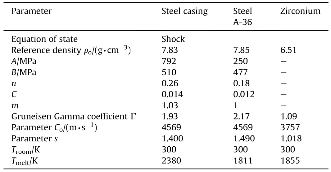
Table B2The input parameters for steel and liner materials.
Water is the standard wellbore fluid used to test the OWP.The EOS of the water layer is a linear model described by

the reference density of water ρ=1 g/cmand its bulk modulus K=2.23 GPa [14] with a reference temperature of T=300 K.
The concrete EOS is described by P-α model,which was proposed by Herrmann [33].This model gives the correct behavior at high stresses,meanwhile provides a reasonably detailed description of the compaction process at low stress levels.This model was validated by Heider [34].The porosity α is defined as

where v=1/ρ is the current specific volume of the porous material(ρ is the current density of the porous material);v=1/ρis the specific volume of the solid matrix material at the same pressure and temperature.This model describes the EOS of porous materials for a complete range of pressure in different stages from elasticplastic deformation regime to the fully compacted solid material,at which the porosity equal unity.The P-α model will not be repeated here,but the characteristics of the porous concrete materials are listed in Table B3.The strength model used with P-α was the RHT (Riedel-Hiermaier-Thoma) brittle material constitutive model [35].This model describes the dynamic resistance of concrete and other brittle material such as rock and ceramics by the combined plasticity and shear damage,in which the deviatoric stress in the material is limited by the generalised failure surface.Generally,the RHT model consists of five parts,i.e the failure surface,the elastic limit,the strain hardening,the residual failure surface and the material damage.Further details of RHT model can be found from Refs.[36].The input parameters for RHT model are listed in Table B3.
The RHT strength model has been used for the modelling of high strain-rate deformation of concrete and other brittle materials.This model has been validated by Vanessa and Dale [28] and Lepp¨anen[37] who implemented a bi-linear softening law that modifies the strain-rate dependency in tension,and hence,improves its capability to model spalling,cracking and scabbing phenomena when a kinetic energy(KE)projectile impacts a brittle target(e.g.concrete).Hayhurst et al.[38] validated these models using Lagrange and Euler solvers with SPH for hard penetrator impacting on ceramic armour.Adel [39] also validated the RHT Lagrange model in the modelling of an ogive-nosed KE rod penetrator penetrating into limestone target.The penetration depth using Autodyn hydrocode including RHT model showed good agreement with experimental tests.
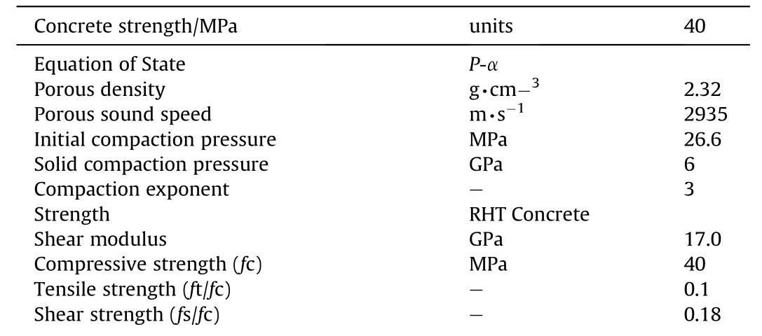
Table B3The input parameters for the RHT strength and failure model.
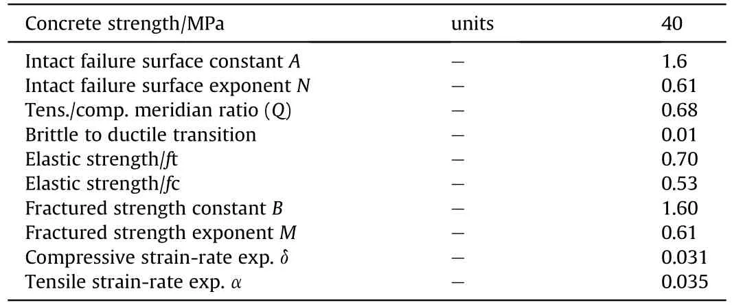
Table B3 (continued)
Appendix C.The numerical calculation of the critical collapse angles β at different V values
The analytical model used to calculate the critical collapse angles at different flow velocities is obtained based on the momentum balance according to

where P is the pressure,ρis the initial liner density,μ is the compressibility (i.e.μ=ρ/ρ-1).
The critical collapse angles can be determined for a given impinging velocity Vfrom the condition dβ/dμ=0 [7].Thus,for β=β

EOS of the liner material should be used with Eq.(C2) to calculate the critical collapse angles βat different values of V.Shock EOS of liner material has the following form

where Cis the sound speed of the liner material and S is the slope of the shock speed-particle velocity line.For the zirconium material,S=1.018.
From Eq.(C3),

For simplicity,assume S ≈1,therefore Eq.(C4) is reduced to

Equating Eqs.(C2) and (C5) and solving it,the critical compressibility(i.e.μ)can be obtained.The obtained values for μwere substituted into Eq.(C3) to get the corresponding critical pressure P.The Values of μand Pare then used with Eq.(C1)to get β,i.e.
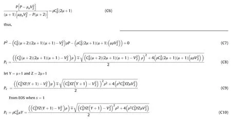
or which can be reduced to

Substitute the values of Y and Z,Eq.(C15) can be expressed as

For zirconium material,ρ=6510 g/cmand K=98.5 GPa,then the critical compressibility μand the critical pressure Pcan be obtained from Eqs.(C18) and (C3),respectively,at a given flow velocities V,and the critical collapse angle can be determined from Eq.(C1).
- Defence Technology的其它文章
- Defence Technology
- A study on the surface overpressure distribution and formation of a double curvature liner under a two-point initiation
- Performances and direct writing of CL-20 based ultraviolet curing explosive ink
- One-step synthesis of FeO(OH) nanoparticles by electric explosion of iron wire underwater
- Driving force coordinated control of an 8×8 in-wheel motor drive vehicle with tire-road friction coefficient identification
- Monitoring and Prediction of the Vibration Intensity of Seismic Waves Induced in Underwater Rock by Underwater Drilling and Blasting

