
Effects of geometry variations on tandem airfoil interaction noise
2020-08-08 02:46:28ZHANGChiSONGWenbin
空氣動力學學報 2020年3期
ZHANG Chi, SONG Wenbin
(School of Aeronautics and Astronautics, Shanghai Jiao Tong University, Shanghai 200240, China)
Abstract:Interaction noise of a tandem airfoil configuration is studied using high-order large eddy simulations (LES) methods on a multi-block structured grid. The sound could be generated from aerodynamic interactions between the two airfoils positioned one after the other. The flow field is first calculated, and spectral properties of pressure fluctuations at a few given observation points are analyzed. The far-field noise obtained using FW-H integration is presented for the base configuration. The interaction from the wake of the airfoil in the front could interact with the leading edge of the trailing airfoil for specific configuration settings. The geometric features of both airfoils are also varied simultaneously to study the combined effects on the noise. The impact of geometric characteristics of trailing-edge and leading-edge of the front and rear airfoil, respectively, is the focus of the research. A typical surrogate-based approach is deployed in this study to reduce computational costs. The results show that, by careful tuning of the geometry and configuration, aeroacoustic characteristics of the tandem airfoil configuration could be modified to achieve lower acoustic levels.
Key words:aeroacoustics; high order scheme; tandem airfoil; interaction noise; FW-H method; response surface
0 Introduction
The noise standards for commercial aircraft operating in civil airspace surrounding airports are becoming increasingly stringent. The proposal from the Advisory Council for Aviation Research in Europe (ACARE) aims to achieve a 10 dB reduction by 2020[1]. Compared with the present Chapter 4 standard, the noise standard introduced by the International Civil Aviation Organization (ICAO) in February 2010 requires civil aircraft airworthiness noise emission to be reduced by 7 EPNdB[1]. The goal of N+3 generation NASA research aircraft wished to gain a 52 dB reduction in combined noise levels by 2025 compared to that of aircraft entering service in 2000[1]. Huge challenge is faced by engineers considering the gap between the state of the art and ambitious objectives set by the relevant organizations.
Aircraft noise comes primarily from two sources, including airframe noise and engine noise. Both need to be reduced to a comparable level to achieve the overall objective of noise reduction. Aerodynamically generated noise is a major mechanism for aircraft noise. Two primary sources for aircraft noise are landing gear and high-lift devices. A number of different noise generation mechanisms have been identified in the literature. The interaction noise between two airfoils placed in tandem configuration has gained interest because it represents one of many typical configurations for aerodynamic noise generation. For example, high bypass ratio turbofan engine and contra-rotating open rotor (CROR) engine may lead to further reductions in fuel consumption, but will likely lead to higher noise levels compared to the current turbofan engines. The levels of noise generated from the interactions between rotor/stator in the turbofan engine and front/aft rotor in CROR can be higher than that of the self-noise of the rotor. In the take-off and landing configurations, the wake and vortex of the main wing would also interact with the horizontal tails. In these cases, interaction noise becomes one of the dominant sources. Such a configuration, though slightly different type, can also be found in typical landing gear configurations, in which, the wake shed from components in the upstream interacts with components in the downstream, generating a major source of noise for the take-off and landing configurations. The interactions of the wake from the front airfoil with the second airfoil are the primary research focus of the current paper.
Changes in the geometry of leading-edge and trailing edge ofairfoils, rotors or stators and their relative position will alter the surrounding flow field, hence leading to changes in the noise generation as well as aerodynamic characteristics of the configuration. To accurately predict the noise level and study possible means for noise reduction, simplified configurations of two cylinders or rod and airfoil placed in tandem were studied widely in the literature. However, for tandem airfoil configurations, most related studies were focused on the aerodynamic performance. Studies on acoustic characteristics with numerical methods are relatively insufficient to the authors’ knowledge. There are several mechanisms of the sound generation of an airfoil in the flow field. Such noise can be divided into two categories: tonal noise and broadband noise. Broadband noise generated from the turbulence of flow is highly disordered. Therefore, the noise covers a broader spectrum of frequencies. The tonal noise is typically related to the flow feature with a certain stable periodic pattern. The noise sources of isolated airfoil include the following four items according to the paper by Migliore and Oerlemans[2]:
a) Turbulent boundary layer-trailing edge noise.
b) Laminar boundary layer-vortex shedding noise.
c) Separation stall noise.
d) Trailing-edge bluntness noise.
The presence of the rear airfoil in the tandem configuration leads to interaction noise, and also self-noise of rear airfoil into the domain. The wake and the vortex shedding from the front airfoil will possibly impinge on the leading edge of the rear airfoil, hence generating interaction noise, which is affected by the geometry of both airfoils.
This paper presents a computational study into the effects of changes in the geometry of the leading edge of the rear airfoil and trailing edge of the front airfoil could have on far-field noise. LES (Large Eddy Simulation) method from an in-house code is adopted in this paper to calculate the flow field. The far-field noise is obtained by FW-H method. The methodology used in the current paper is validated against benchmark cases to demonstrate its capability for noise prediction. NACA 0012-63 is chosen as the baseline airfoil in this paper. Mach number is kept constant as the takeoff and approach speed of aircraft is nearly 0.2 with a Reynolds number of 105. The combined effects of geometry variation from two airfoils are studied. The conclusions are drawn on the noise implications. This could be coupled with aerodynamic analysis in further studies.
This paper is organized as follows: Section 1 presents the related work about the models and numerical methods. Section 2 introduces the methodology used for modeling the flow and calculating the sound. Validation is given by comparing results with benchmark cases. Section 3 presents the calculation result of the case using NACA 0012-63. Furthermore, a surrogate-based approach is used to study the geometry variations of the trailing edge of the front airfoil and the leading edge of the rear airfoil. Section 4 concludes the results obtained from the last section.
1 Related work
1.1 Typical models and configurations
Tandem cylinder and rod-airfoil models have been investigated by many researchers using numerical and experimental methods. The widely mentioned tandem cylinder experiments were conducted in NASA Langley Research center at the Basic Aerodynamic Research Tunnel (BART) and Quiet Flow Facility (QFF). Experimental results revealed some flow features in this configuration with the two spaced at a diameter ratio of 1.435 and 3.7[3], respectively. Fifteen tandem cylinder solutions on the First Workshop on Benchmark problems for Airframe Noise Computations were summarized in the paper by Lockard[4]. There were also other studies related to the configuration, many of which are focused on flow control technology.
Rod-airfoil interaction noise generated at low Mach number was investigated numerically by Casalino[5]with 2D URANS method. The spanwise effects were introduced into the time-domain formulation of the FW-H analogy by a statistical model. The results with spanwise correction compared very well to the accompanying experiment. Jacob conducted a low Mach number test on rod-airfoil in the large anechoic wind tunnel of the Ecole Centrale de Lyon, and a 2D URANS combined with a spanwise stochastic model was compared with the experiment[6]. Two CAA (Computational AeroAcoustics) methods were compared and validated with Jacob’s experiment by Schell[7]. A direct noise calculation with compressible DES (Detached Eddy Simulation) and a hybrid method with DES and Lighthill analogy were applied with StarCCM+. The calculations were three dimensional with a span of 0.3 m, which were the same as in the experiment. An incompressible LES coupled with Lighthill’s equation was used to predict the noise of rod-airfoil by Eltaweel[8]and again compared with Jacob’s[6]experiment. Most of these works identified that the leading edge is the dominant sound source.
The effects of the geometry of isolate airfoil on the turbulent noise were studied numerically by Gill[9]. The dominant noise reduction mechanism was found to be related to the thickness and leading-edge radius of NACA series airfoil. The result was compared with an analytic flat plate that over-predict the noise by 3 dB at high frequencies. Paruchuri[10]extended Gill’s work to experiment with airfoil printed by 3D printer. Their work focused on the interactions of an isolated airfoil with the gust of a specific wavelength.
As to the tandem airfoil configuration, most of the related studies were based on the background application in turbomachinery. McGlumphy[11]investigated the feasibility of using a tandem rotor in the rear stage of a core compressor. Laurent[12]studied the aerodynamic performance of tandem airfoil under a high angle of attacks. Shirsath[13]explored the effect of the angle of attack of the rear airfoil on unsteady aerodynamic quantities. It is to the author’s best knowledge that the aeroacoustics characteristics of two airfoils in a tandem configuration have not been sufficiently studied in the reported literature.
It can be seen from the above that most of the researches focused on the flow condition and the geometry effects of an isolated airfoil. And the turbulence interaction is modeled with isotropic turbulence or generated by the wake of a rod. The wake of an airfoil and the geometry effect on interaction noise have not been studied numerically yet. In this paper, the background application the configuration corresponds to the take-off and approach flight conditions of aircraft. The flow conditions in the calculation stay unchanged while geometries of the two airfoils were varied.
1.2 Numerical study
In a typical CAA approach, three distinct phases are often used, including the calculation, extraction and characterization of the noise source, propagation calculation and analysis of noise levels at the receiving points. Accurate identification of noise sources using either numerical and experimental methods is a challenge. Numerical methods have a long term potential value as these can be integrated into the design process to study the effects of relevant factors such as geometry, configuration, and the effectiveness of noise reduction measures. It has become common practice to use RANS in aerodynamic design in industry settings on complex configurations; this has not been possible for noise calculations on realistic configurations due to the extremely high computational cost. Significant efforts are still required from the three areas of noise generation, propagation and characterization of observed noise. The current study focused on the problem of broadband noise generation for tandem airfoil configurations in order to further the state-of-the-art in the fields, development of hybrid approach appropriate for the simulation, improved understanding, characterization of noise generation mechanisms and more efficient numerical algorithms on massively parallel high-performance computing facilities.
Jacob[5]also compared 2D URANS with 3D URANS and concluded that though 2D URANS over predicted the shedding frequency, the 3D URANS did not improve the shedding frequency significantly because of the intrinsic deficiency of the URANS formulation. Yi Jiang studied the rod-airfoil interaction noise with high order LES method[14]. The spacing between the rod and airfoil was studied as well. It was found that three modes of interaction exist for the variation of spacing.
Liu[15]studied the trailing edge serration technology on the interaction noise of tandem airfoil without looking at other geometry variations. The chosen airfoil is the NACA-65 series, which was widely used in the propeller design. The aft airfoil is placed in the mirrored vertical direction. Chen[16]investigated the geometry optimization of a tandem airfoil at a low Mach number on aerodynamic performance. The geometry and relative positions are varied with 23 design variables in total.
2 Numerical methods and validation
2.1 Sound source and acoustic analogy model
Far-field noise is obtained by the acoustic analogy method based on a two-step approach. First, the unsteady flow field around the sound source is simulated with CFD method; Second, the scattering of the sound wave is calculated by solving the wave equation. In this paper, the flow field for acoustic calculation is obtained from the result of LES method. Far-field noise is calculated with the sound analogy model FW-H.
In the current work, LES is used to investigate the noise mechanism of tandemairfoil. A fifth-order weighted essentially non-oscillatory (WENO) scheme is used in the study. Roe method is used for the flux splitting. The temporal integration used is LU-SGS approach. The subgrid-scale (SGS) turbulence model used in this paper is the Smagorinsky-Lilly model. Far-field boundary condition is obtained with the method based on Riemann invariant from the 1-D inviscid flow. Side boundary is set as a symmetric boundary condition.
2.2 Validation using turbulent rod configuration
The experimental data fromBoudet for turbulent rod configuration is used to validate the numerical methods[17]. This configuration is a cylinder flow with an inflow speedU0=72 m/s, temperatureT=293 K andρ=1.2 kg/m3. Reynolds number based on rod diameter is 46000. A circular computational domain with a radius of 80D is used. The computation mesh used is a 181×181×31 sized structured grid. The first layer thickness is chosen as 0.05D(Dis the diameter of the rod andD=0.01m). A growth rate of 1.0359 is used.
The first layer thickness in this paper is varied to investigate its effect on far-field noise. Three values were chosen for the first layer thickness, 0.05D, 0.013Dand 0.005D, which correspond toy+(yplus value) of 3.8, 1 and 0.38, respectively. Circumferential points at Case 2 is increased to study the effect ofx+(relative to the definition ofy+). The non-dimensional time step is set as Δt=0.002. The total flow time is chosen as 100,000 time steps. Acoustic data is sampled every time step, and the sampling frequency is 360 kHz. Table 1 shows the aerodynamic results of different first layer thickness. It can be seen that lowery+value gives a better shedding frequency. The drag coefficients and lift coefficients from these cases did not show much difference.
Figure 1 shows the power spectra density (PSD) of pressure fluctuation in 70D. Seo[18]obtained the result from a two-dimensional LPCE (Linearized Perturbed Compressible Equations) computation with input from LES result. A sixth-order finite difference scheme was used. Strohal number is 0.19 in the experiment. It can be seen that controlling they+value at 1 can obtain better frequency result in comparison with the results obtained by others. For case 2, though the results slightly over predicted the peak frequency, the value agrees reasonably well with the aerodynamic result. It should be noted that only numerical results of pressure at location (0, 70D) was found in the published paper. Therefore, the overprediction at high frequency may result from that smaller scales flow structure was resolved by the finer grid.
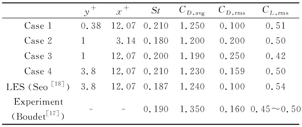
表1 不同網格的圓柱氣動結果Table 1 Aerodynamic results of rod using different grids
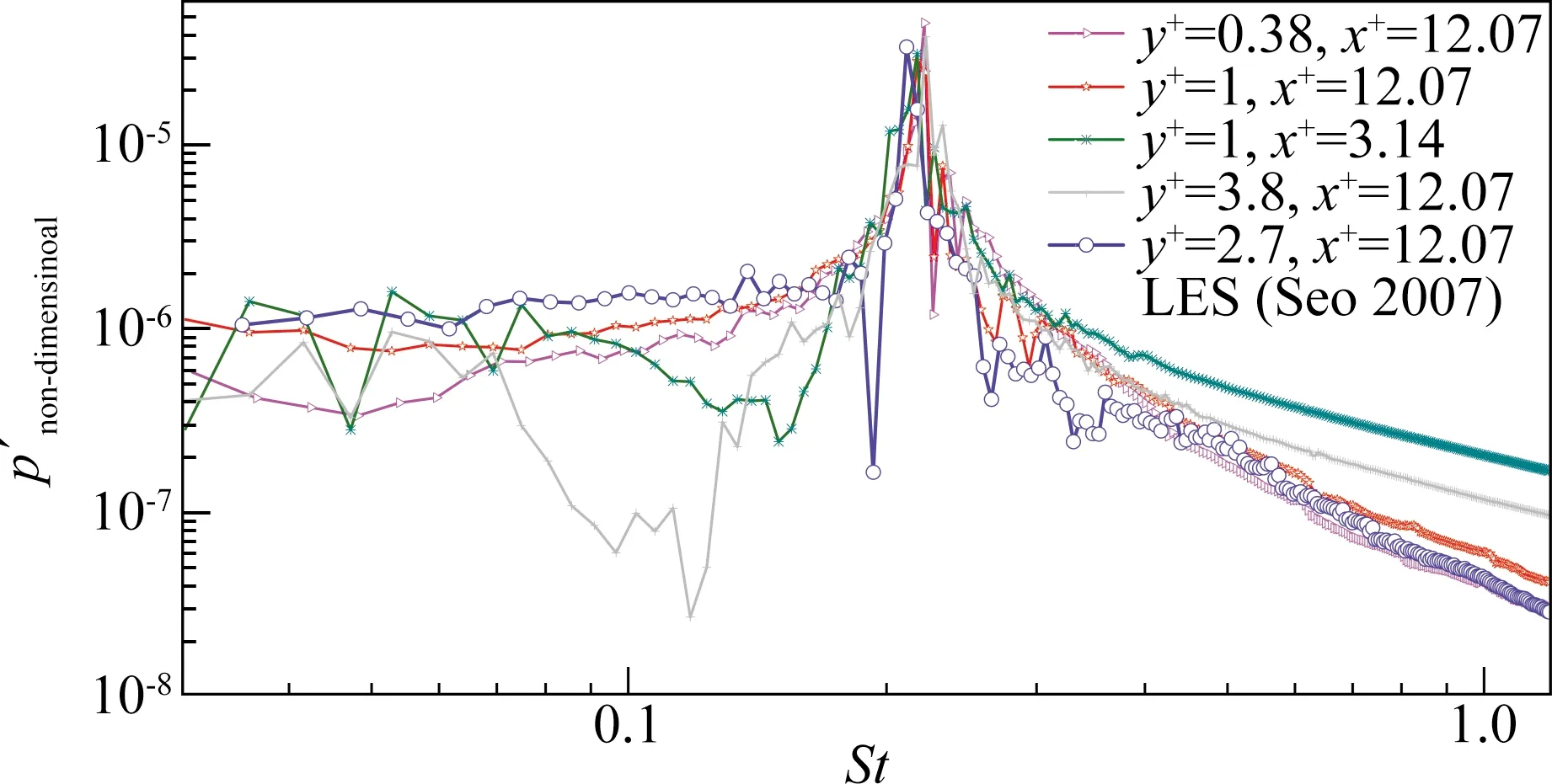
圖1 點(0, 70D)處的壓力脈動自相關頻譜圖Fig.1 Pressure fluctuation auto-correlation spectra at a receiving point of (0,70D)
Figure 3 depicts the span-wise coherence function of surface pressure at the given shedding frequencyf0. It can be seen that the harmonic frequency of shedding frequency decay more slowly than other frequencies. This means the span length is enough for capturing the flow scale apart from those corresponding shedding frequency. Therefore, corrections should be made on the final result. The correction method used here is introduced by Seo[18].
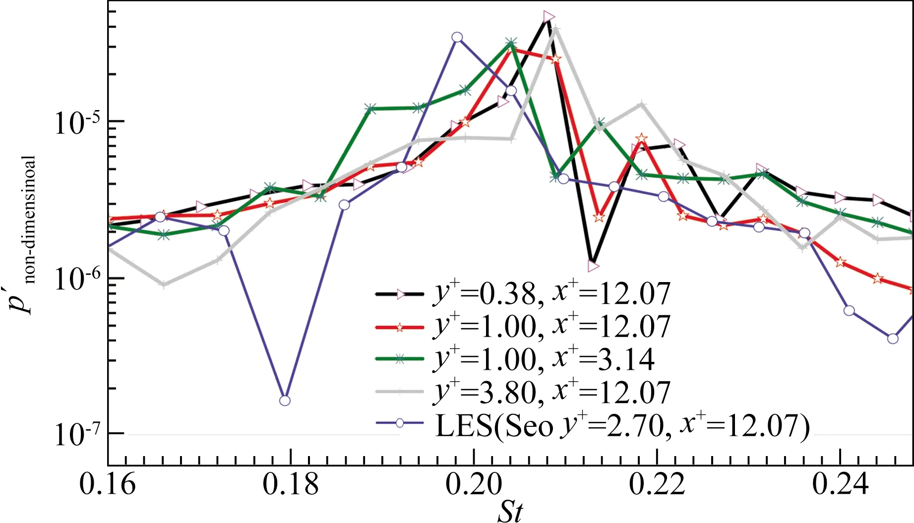
圖2 點(0, 70D)處的壓力脈動自相關頻譜圖(放大)Fig.2 Enlarged auto-correlation spectra of pressure at receiving point of (0, 70D)
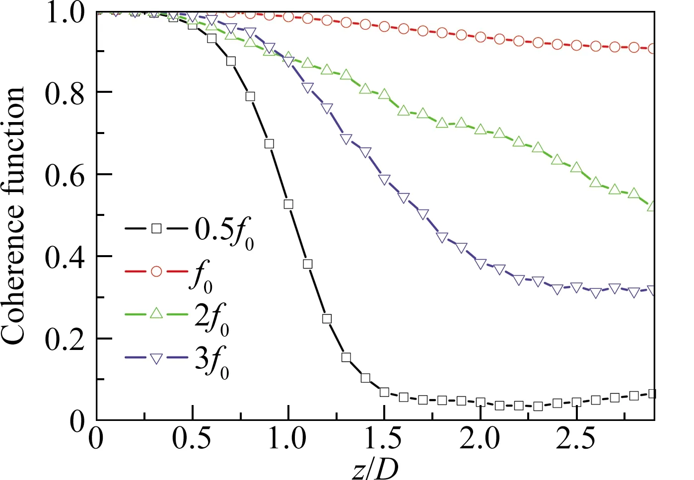
(a) Spanwise coherence coefficient of surface pressure at Shedding frequency over the span (90°)
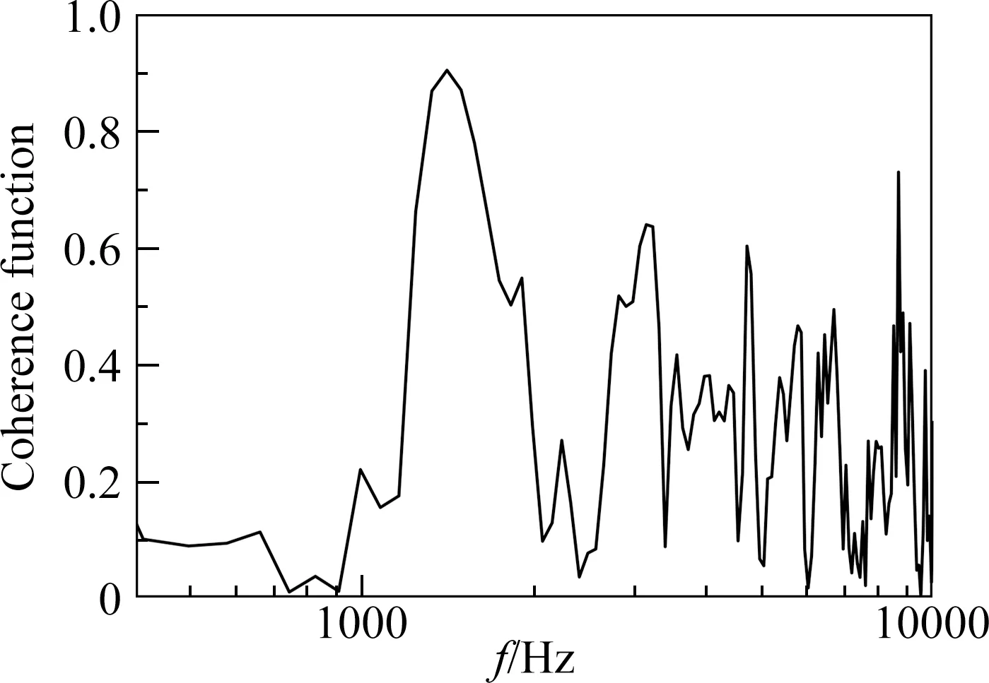
(b) Two-point coherence function of surface pressure over the rod at 90° (z=0 and z=1.5D)
Far-field noise calculated from the FW-H surface overlapped with the rod surface is shown in Figure 4. It can be seen that both the scale and frequency of the tonal noise are well predicted. The harmonics of the main tonal noise are also captured. The high fluctuation of the spectra is the common phenomenon that appears in the calculation of noise, which results from the relatively short length of the total sampling time.
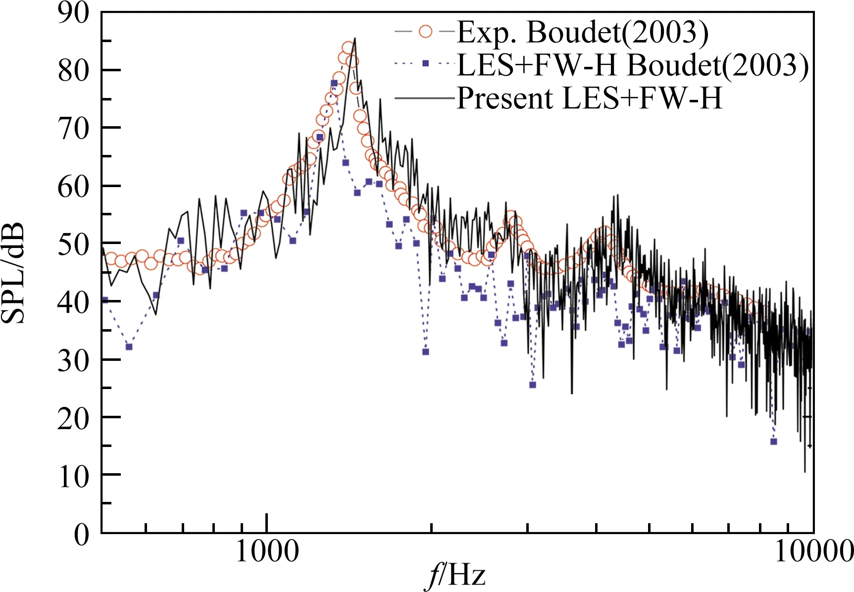
圖4 觀測點(0,1.85 m)處的聲壓級頻譜圖Fig.4 Sound pressure level at receiver point (0,1.85 m)
2.3 Validation using rod-airfoil configuration
The same rod airfoil configuration, as used by Jacob[6], is considered in this validation, as depicted in Figure 5. Freestream flow conditions are set asU0=72 m/s,T=293 K andρ=1.2 kg/m3. The reference chord length is chosen asc=100 mm, which results in a Reynolds number of 4.8×10⁵.
Three grids were compared to validate the meshused for the following studies.yplus values of the first layer in all three grids were kept at 1. The differences were the growth ratio in the normal direction and the number of points along the circumference direction. Table 2 shows the nodes number allocated on the surface of the rod and airfoil.
Total computational domain is set as (-8c,8c) in vertical direction and (-10c,20c) in the horizontal direction. Computational methods are the same as the rod configuration but the non-dimensional time step is reduced toΔt=0.001. The sampling time for acoustic data was 20,000 time-steps and sampled every time step. Sampling frequency was then defined as 720 kHz. Results from RANS of 20,000 iterations were used as the initial values for LES calculation.
The calculation results are shown in Figure 6. Results of three cases are compared with reference LES and experiment results. Turbulent intensity is obtained based on streamwise velocity fluctuations. Considering the rod was shifted 2 mm vertically in the experiment,the velocity profile at position A (x/c=-0.255) shows the greatest velocity deficit at the locationy/c>0. Apart from the result of grid No.2, all simulated cases exhibit a larger averaged velocity deficit compared to experimental results. And turbulent intensities are also larger along the middle line. Despite these differences, it is believed that the results obtained here are acceptable. These phenomena appear in nearly all the numerical simulations of rod airfoil configuration.
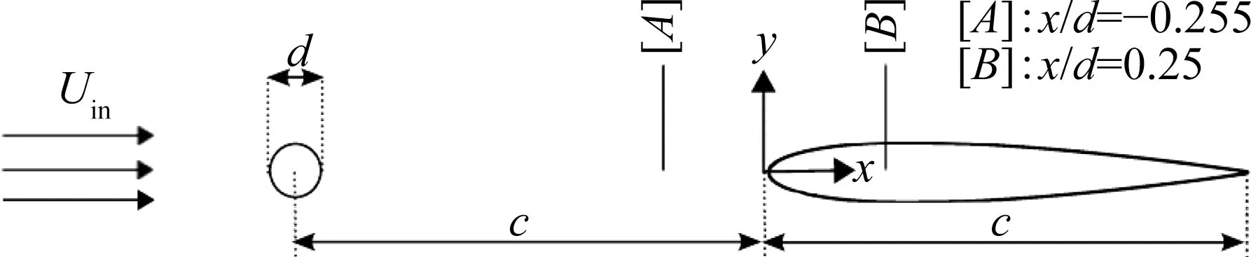
圖5 圓柱機翼構型示意圖[6]Fig.5 Rod-airfoil configuration for validation[6]
By comparing the calculated results of the two cases above, it can be seen that the method used in this paper is feasible in the current study on the geometry variation of tandem airfoil configurations.
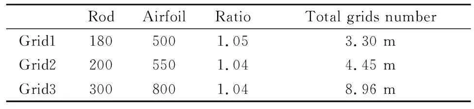
表2 三個圓柱機翼網格的細節(jié)參數(shù)Table 2 Mesh details of three cases
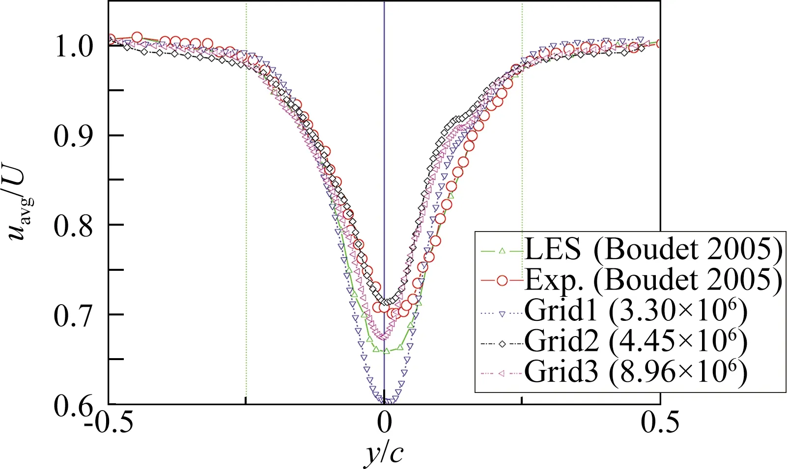
(a) Averaged meanstreamwise velocity profile at x/c=-0.255
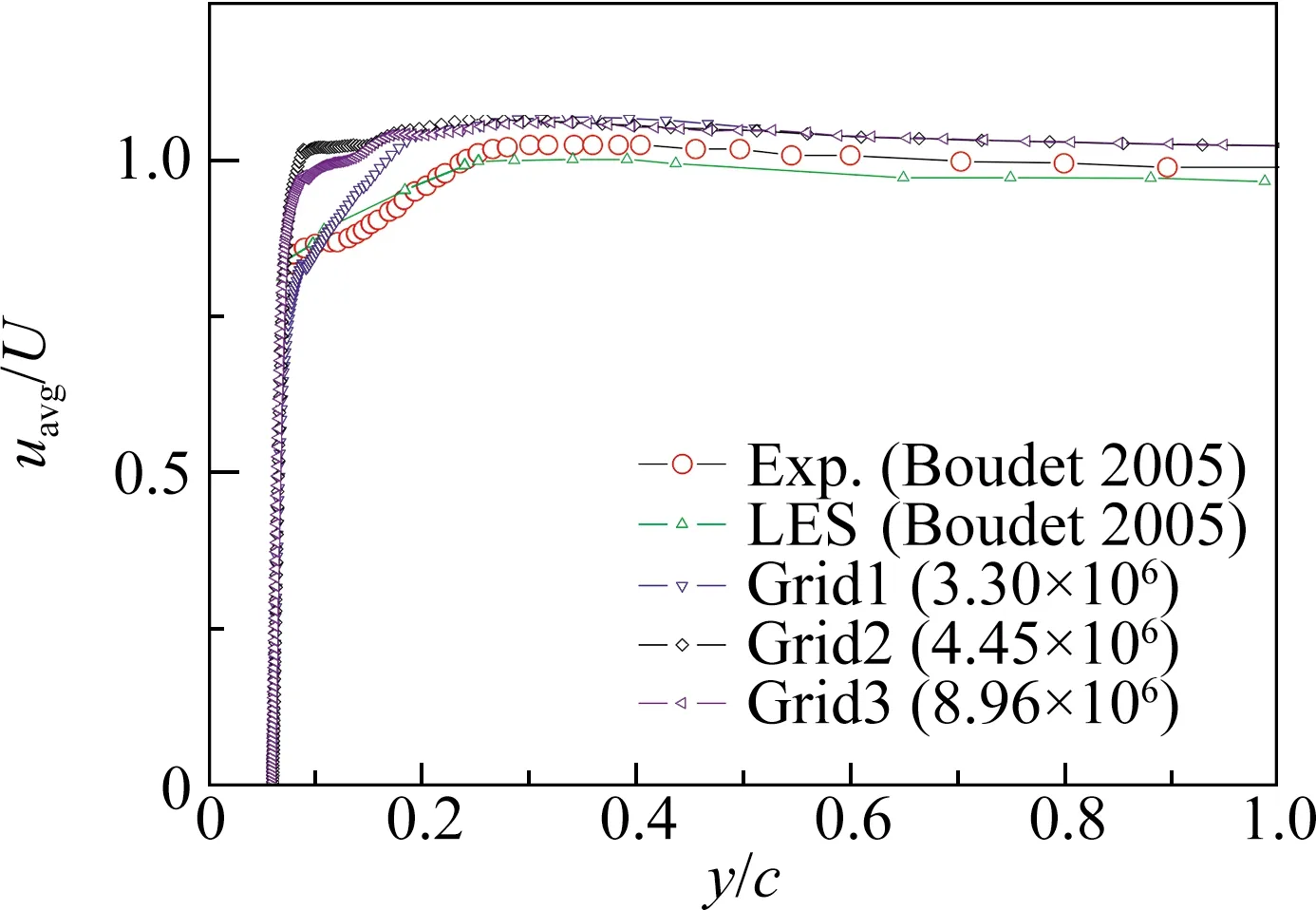
(a) Averaged meanstreamwise velocity profile at x/c=0.25
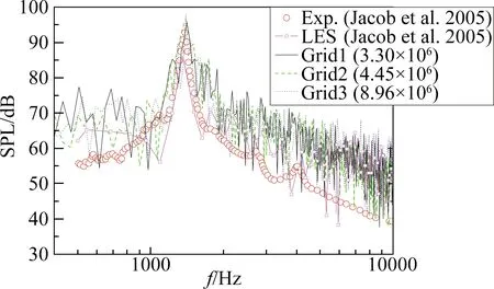
圖8 機翼前緣上方(0,1.85 m)處的遠場SPL頻譜圖Fig.8 Far-field SPL spectra at the location (0,1.85 m) above the airfoil leading edge
3 Aerodynamic and aeroacoustics calculation of tandem airfoil
3.1 Geometry and computational model
The tandem airfoil model used here is a model used in the 1st International Workshop on High-Order CFD Methods[19], as shown in Figure 9. Thedoffis the distance of vertical displacement relative to the chordc.doffis set as 0.24 in this paper and the angle of attack of the front airfoil is set as 10°. Parameterdsepis the horizontal distance between the two airfoils. The airfoil used is NACA0012 and the methods used for generating the airfoil are described in the following.
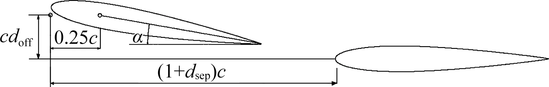
圖9 計算所選用的串聯(lián)機翼模型示意圖Fig.9 Tandem airfoil configuration chosen for computation
Geometry variations are introduced for the leading edge radius and the maximum thickness of the aft airfoil. As for the front airfoil, maximum thickness and boat-tail angle are varied. Class/Shape Transformation method[20]is used to generate varied geometry. Leading-edge radius is related to the maximum thickness through the following expression:
(1)
wheretis the maximum thickness of airfoil, andIstands for non-dimensional parameter that controls the shape of leading edge. The standard NACA 4-series airfoil is defined withI=6.
The model is shown as Figure 9. In this paper, the relative position of two airfoils did not changed, only geometries were varied. The chosen parameters are listed below in Table 3.
表3 串聯(lián)機翼構型的外形參數(shù)Table 3 List of parameters for tandem airfoil configuration
Two NACA0012 airfoils with the same chord ofc=100 mm were placed in tandem configuration with twice the chord length apart between the leading edge of the two airfoils. The front airfoil was rotated around point quarter-chord (0.25c, 0) to achieve an angle of attack of 10°.
O-type blocks are used to discretize the computational domain.Each airfoil surface is meshed with 538 nodes along the circumferential direction. The normal direction growth ratio is set as less than 1.05 near the wall. Total nodes number is 128 in the normal direction near the wall.
It should be notedthat the current noise result is calculated from the finite span 0.2c, as the length of span would directly influence the total noise results. Spanwise length correction has been made for the tandem airfoil cases.
Q-criterion Iso-surfaces of tandem airfoil calculated using LES are shown in Figure 10. Periodic pressure fluctuations are generated from the leading edge shedding vortex on the upper face of the front airfoil. Thick low-speed zone occurs in the wake domain of the trailing edge. Then the vortices are pushed downward by the presence of the aft airfoil, impinging on the upper face of the aft airfoil. Finally, the vortices are mixed with the wake of aft airfoil downstream of the aft airfoil.
圖10 Q準則等值面圖(速度云圖)Fig.10 Q-criterion iso-surfaces for velocity
The turbulence flow is mainly developed at the upper face and trailing edge of the front airfoil, then the upper face of the rear airfoil. These areas are likely to be the primary regions for noise sources. The SPL (sound pressure levels) spectra are shown in Figure 11. Three FW-H integration surfaces comprised of the front airfoil and aft airfoil, and tandem airfoil were used to obtained the far-field results of the three lines, respectively. It can be seen that aft airfoil is the dominant noise source in the overall model. The maximum SPL frequency of aft airfoil in the tandem configuration is totally different from the isolated condition, which has a max SPL frequency of about 2700 Hz[21]. This is similar to the rod airfoil configuration. Therefore, the following work in this paper focused on the trailing edge of the front airfoil and the leading edge of aft airfoil.
圖11 接收點(0,1.85 m)處的串聯(lián)機翼遠場聲壓級頻譜圖Fig.11 Sound pressure level of the tandem airfoil at the receiver (0, 1.85 m)
3.2 Surrogate-based study of shape parameters
This section adopted aresponse surface methodology to study the combined effects of variations in these geometric features on noise levels[22]. A Latin hypercube sampling method is used to generate a set of sample points. A series of Kriging based surrogate models were generated in order to find the best combinations of these geometry parameters regarding noise level reduction at the observation points. The response surface will demonstrate the combined effects of these geometry features and provide an insight into the design of future lower noise configurations.
Four parameters were chosen in the study of the combined effect, including maximum thickness and boat-tail angle of the front airfoil, leading-edge radius and the maximum thickness of the aft airfoil. The ranges of these four parameters are listed in Table 4.
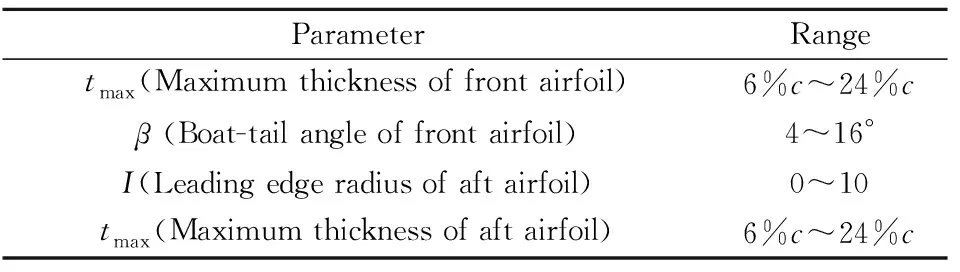
表4 幾何外形參數(shù)變化范圍Table 4 Range of variations for geometry parameters
A total of 30 sample points were obtained for the generation of the response surface. TheR2value is defined as the following to describe the accuracy of the model.
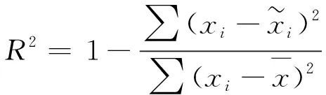
(2)

As Figure 12(a) shows, OASPL is increased with the maximum thickness when the boat-tail angle is low. Moreover, the two curves become closer when the maximum thickness is greater than 15% of the chord. That means that a low boat-tail angle has very few effects on OASPL when the maximum thickness is large. Judging from the different trend at low and high boat-tail angle, it is reasonable to presume that there is a certain range of ratios between maximum thickness and boat-tail angle that give the lowest sound emission. This ratio makes sure that there is a smooth transition from the maximum thickness point to the trailing edge. Figure 12(b) shows a similar trend as in Figure 12(a) apart from the fact that two curves are overlapped.
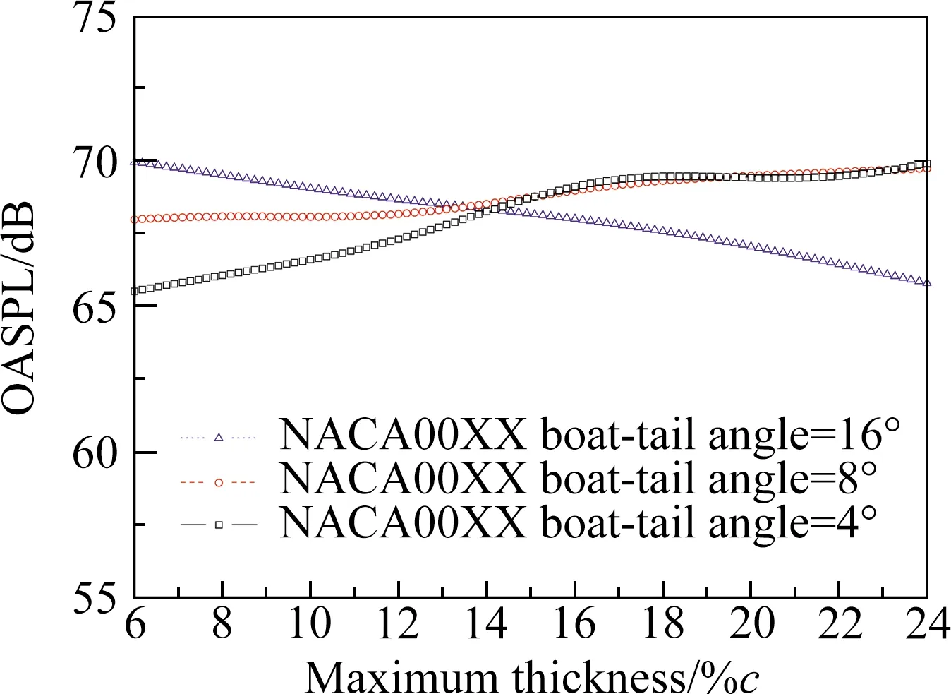
(a) The effect of maximum thickness at different boat-tail angles
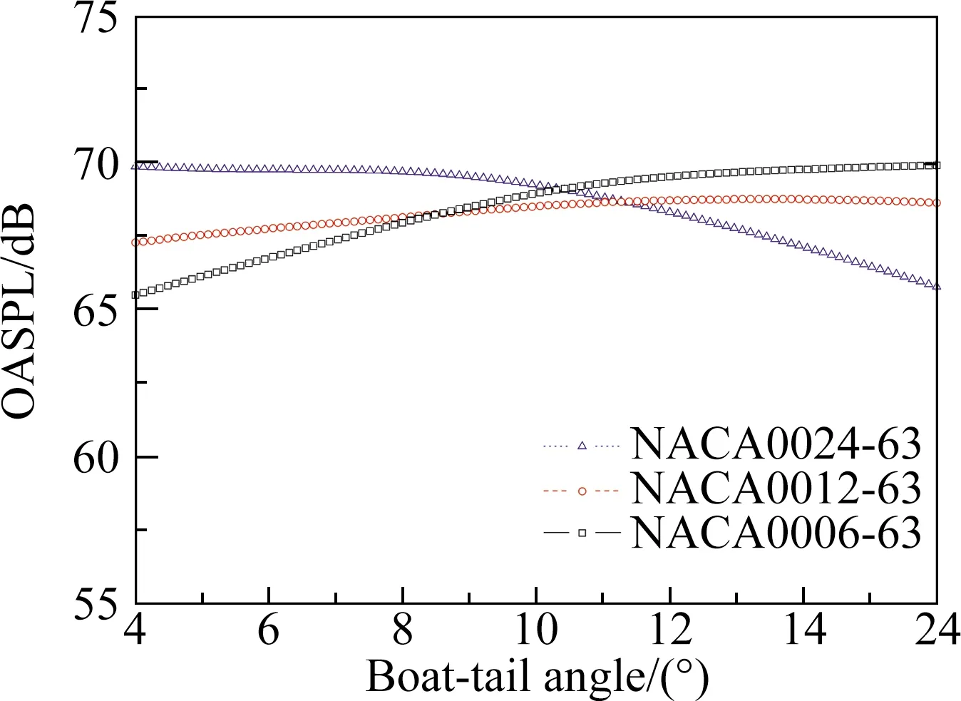
(b) The effect of boat-tail angle
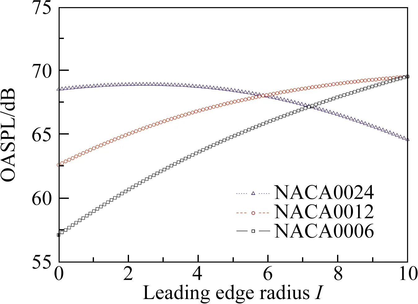
(c) The effect of leading edge radius
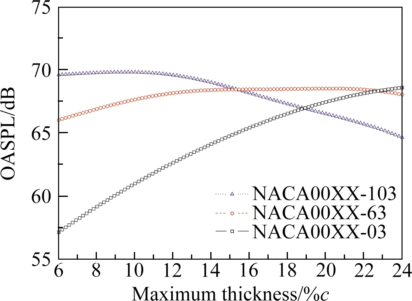
(d) The effect of maximum-thickness for different airfoils
As to Figure 12(c), OASPL increases withI(leading edge radius) at small maximum thickness. Sharper leading edge can reduce the direct impingement of vortex on the surface of the aft airfoil, driving the vortex downstream more smoothly. While at larger maximum thickness, OASPL is smaller with largerI. In this case, the front of aft airfoil in inevitably large, leading to higher blockage at the leading edge. Sharper leading edge would make the pressure at the static zone higher. Whereas rounded leading-edge could relieve this phenomenon. Figure 12(d) shows a similar trend as Figure 12(c).
The response surface is plotted with HAT (Hierarchical Axes Technology) graph. The effects of four parameters on OASPL are plotted. Variables in the outer axis are front airfoil maximum thickness in thexdirection and boat-tail angle in theydirection. In the inner coordinate, two variables are aft airfoil leading-edge radius in thexdirection and maximum thickness in theydirection.
Far-field OASPL of the front airfoil is shown in Figure 13, wheretmaxmeans front airfoil thickness, andβmeans front airfoil boat-tail angle. It can be seen that front airfoil OASPL is less sensitive to the effect of aft airfoil geometry. The highest OASPL lies in the subplot (1,3) and (3,1). The counterpart front airfoil geometry is the combination of smalltmaxwith smallβ, and largetmaxwith largeβ. When an airfoil is featured with slim rear shape, namely low boat-tail angle, noise is decreased with the increase of maximum thickness. This conclusion is similar to that of James[9]. But the trend is reversed when the boat-tail angle is high. In this case, geometry has a blunt trailing edge. Because the scale of vortex shedding from the trailing edge is increased, making the airfoil thickness larger may worsen this phenomenon.
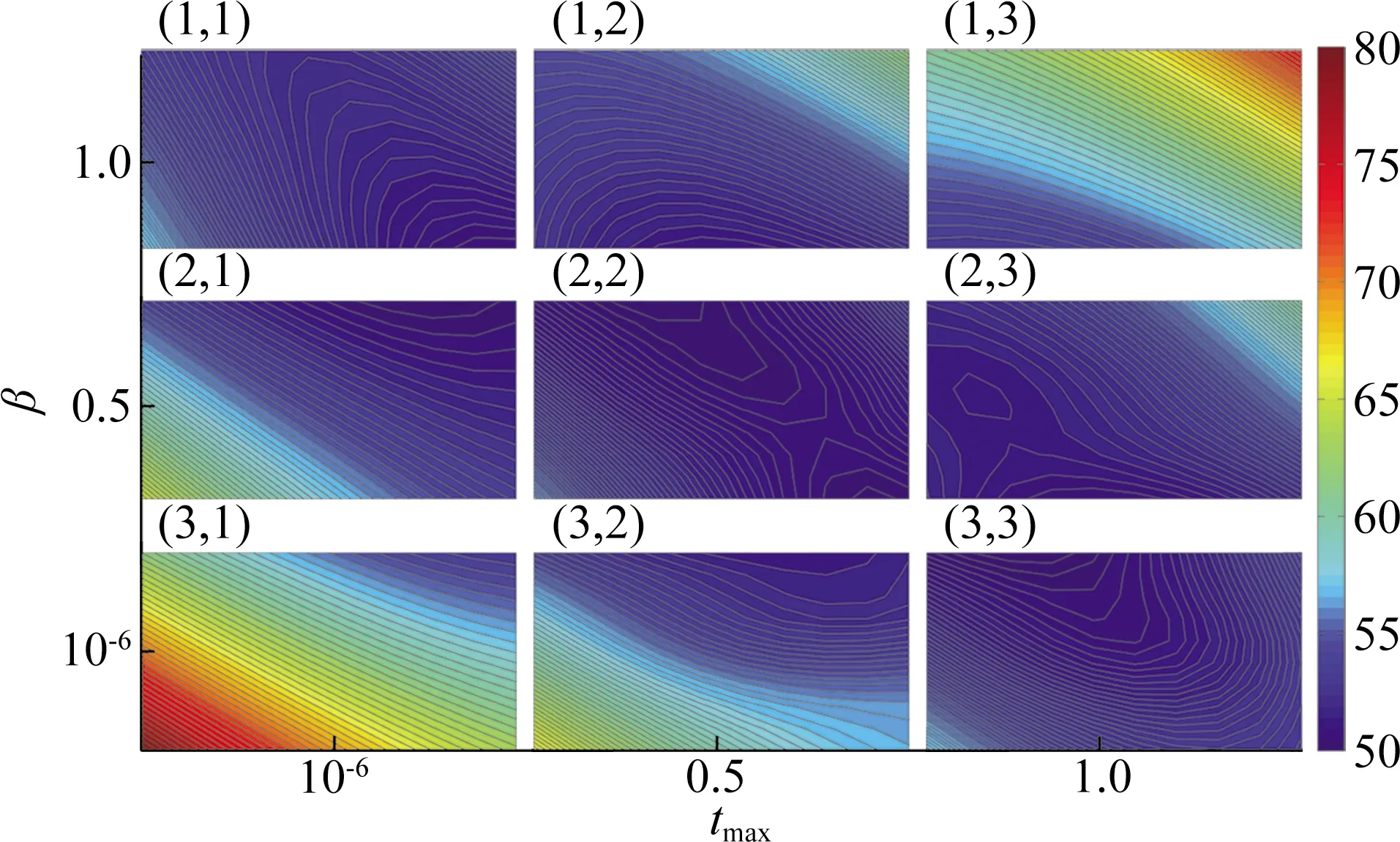
圖13 接收點(0,1.85 m)接收到的前翼OASPL圖
Figure 14 depicts the overall noise of the front airfoil and aft airfoil. It is obvious that tandem airfoil OASPL is more sensitive to the aft airfoil geometry. Two trendscan be observed from the HAT graph. The first one is that the trend is totally opposite in subplot (3,1) and (1,3). When front airfoiltmaxandβare small, tandem airfoil noise is larger if aft airfoiltmaxorIbecome larger. The second is that in the rest of the subplot, OASPL is lower when aft airfoil maximum thickness and leading-edge radii are either smaller or larger.
The primary areas with low OASPL lie on the line between Figure 14 subplot (1,3) and (3,1). But the counterpart of this area in Figure 13 is the lowest noise areas of the front airfoil. It should be noted that aft airfoil takes the dominant position in tandem airfoil configuration. Figure 13 and Figure 14 show the opposite trend in subplot (3,1) and (1,3), since the response surfaces were generated from single front airfoil and tandem airfoil, respectively. The effect of the front airfoil is overwhelmed by aft airfoil.
Figures 15 and 16 show the frequency obtained at max SPL. It is easy to find that the frequency has a very similar trend as max SPL. That means louder noise is accompanied at higher frequencies.
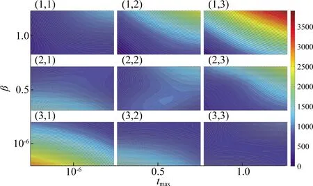
圖15 接收點(0,1.85 m)接收到的前翼最大聲壓級對應的頻率圖Fig.15 Max SPL frequency of front airfoil at the receiver (0,1.85 m)
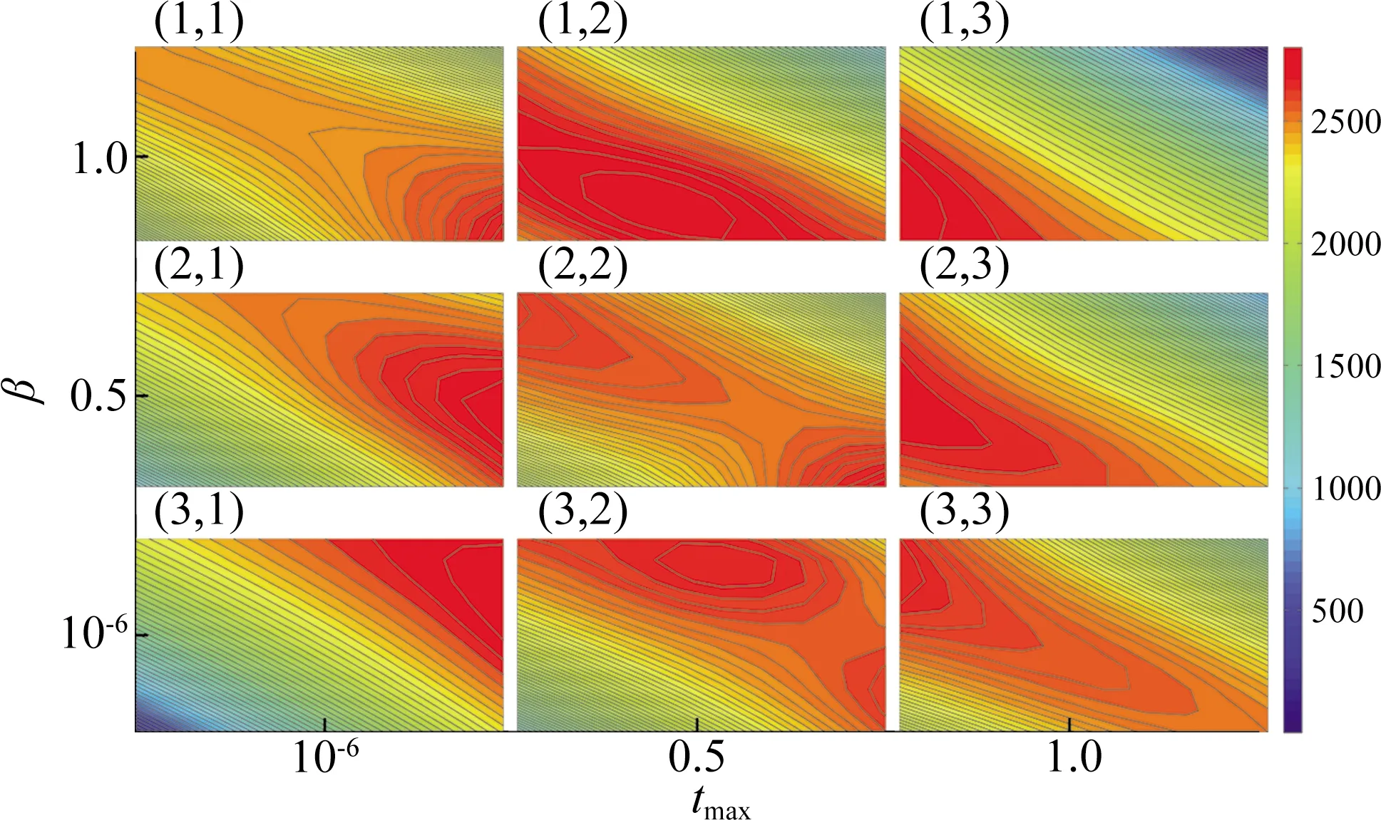
圖16 接收點(0,1.85 m)接收到的串聯(lián)機翼最大聲壓級對應的頻率圖Fig.16 Max SPL frequency of tandem airfoil at the receiver (0,1.85 m)
4 Conclusions
Far-field noise characteristics of typical tandem airfoil configuration have been studied numerically with 3D LES combined with FW-H analogy. Geometric features of both airfoils are varied simultaneously to study the combined effects on noise. The results of four geometry parameters: front airfoil maximum thickness, front airfoil boat-tail angle, aft airfoil leading-edge radius and aft airfoil maximum thickness, have been investigated. The key findings are listed as follows:
1) Geometries of both airfoils in tandem airfoil configuration should be considered for noise reduction. Since the reduction of noise from the front airfoil alone could worsen the overall noise level of the tandem airfoil configuration.
2) The ratio between maximum thickness and boat-tail angle of front airfoil should bekept in a certain medium range. Too large or too small would worsen the aeroacoustics performance. This can avoid the sharp change in geometry that may induce vortex generation. Keeping the transition of flow from the maximum thickness point toward trailing edge could also avoid large trailing edge vortex.
3) Sharp leading edge should only be used in a thin airfoil. Larger leading-edge radius should be used under the circumstance that maximum thickness islarge. Namely,Iandtmaxshould be both large or small at the same time in most cases.
4) Noise frequency of max SPL has a similar trend as the max SPL. The frequency for the Max SPL should be carefully considered in order to avoid undesirable effects such as acoustic fatigue.
The complex interactions between two airfoils in a tandem configuration make it necessary to consider the case using an integrated approach. The current study should be further extended to include spanwise effects for the same tandem configuration in the next steps of the research, along with comparative studies using an experimental approach. In reality, aerodynamic aspects should also be considered, which further complicates the problem.
From the results, it is also suggested that configuration parameters such as the vertical and horizontal distance, and spanwise variations, should be included in the future, three-dimensional studies.
猜你喜歡
電動工具(2024年1期)2024-02-29 01:40:24
計量學報(2020年2期)2020-04-11 04:33:22
演藝科技(2019年4期)2019-03-30 03:21:46
測控技術(2018年9期)2018-11-25 07:44:12
石油地球物理勘探(2018年6期)2018-03-22 03:05:26
湖南大學學報(自然科學版)(2016年5期)2016-08-25 08:19:53
火控雷達技術(2016年2期)2016-02-06 02:28:51
應用聲學(2015年3期)2015-10-27 02:52:49
電子設計工程(2015年12期)2015-02-27 12:06:06
中國艦船研究(2014年6期)2014-05-14 06:45:17
