
Physical investigation on the behaviours of voussoir beams
2020-07-12 12:35:16ChoshiHuDerekApelLesJozefSudkWeiVitorLiuZhoyunChu
Choshi Hu, Derek Apel, Les Jozef Sudk, Wei Vitor Liu, Zhoyun Chu
a School of Mining and Petroleum Engineering, Department of Civil and Environmental Engineering, University of Alberta, Edmonton, T6G 1H9, Canada
b Department of Mechanical and Manufacturing Engineering, University of Calgary, Calgary, T2N 1N4, Canada
c Anhui Yitong Construction Consulting and Management, Ltd., Yuexi, Anqing, 246000, China
Abstract It is important to understand the behaviour of voussoir beams in the design of underground excavations.There are a large number of discrepancies between the results obtained by different researchers so far.To resolve these discrepancies, physically testing the stress distribution at the midspan and abutment of voussoir beam is the key.In this paper,a simple two-block voussoir beam was built with loading system.The displacement and strain of the voussoir beam were measured by a digital image correlation system.The strain distribution along the joints of voussoir beams was firstly revealed. Then, the relationship between transverse load and midspan displacement of voussoir beam was presented.It is found that the stress distributions at the midspan and abutment are different both in shape and depth. The stress distribution is changing as the loading changes as well.
2020 Institute of Rock and Soil Mechanics, Chinese Academy of Sciences. Production and hosting by Elsevier B.V. This is an open access article under the CC BY-NC-ND license (http://creativecommons.org/licenses/by-nc-nd/4.0/).
Keywords:Voussoir beam Stress distribution Image correlation
1. Introduction
Stratified rock masses are often encountered in underground excavations.The stratified roof is usually cut by discontinuities.The discontinuities could be the joints or faults which exist before excavation or the appearance of tensile fractures caused by excavation. The stratified roof should therefore be treated as jointed beams rather than intact, elastic beams. It is widely accepted that the self-support ability of jointed beams develops from the compression arch formed within the beam under transverse loading. Voussoir beam theory is a method for assessing the stability of a stratified roof based on the arching mechanism,as shown in Fig. 1. Voussoir beam theory has been applied widely in the design and stability analysis of underground excavations. For example,it has been used for back-analysing the failure of a mining roof(Alejano et al.,2008),assessing the stability of an underground memorial site (Hutchinson et al., 2008), controlling the strata behaviour in an underground long-wall mining face (Ju and Xu,2013), and analysing the roof collapse after extraction of a coal pillar (Please et al., 2013).
The first analytical approach to describe the deformations of cracked roof beds was made by Evans (1941). His analysis considered that cracks are created at the abutment and midspan of the rock beam.He assumed that the stress distributions induced at the abutments and midspan are triangular in shape and extend an equal distance,nt,over the depth of the beam,wherenis the ratio of the depth of stress induced at the abutment to beam thickness andtis the thickness of the voussoir beam. Furthermore, he assumedn0.5,i.e.the depth of induced stress was equal to half of the thickness of the beam.The design procedure proposed by Evans was later modified by Beer and Meek (1982). Sofianos (1996) and Diederichs and Kaiser(1999)noted some limitations in a simplified version of Beer and Meek (1982)’s method and proposed alternative ways of addressing the static indeterminacy of roof-bed analysis.Diederichs and Kaiser(1999)proposed an algorithm to test the stability of a voussoir beam against snap-through and crushing based on the assumption that there will be the same linear stress at the abutment and midspan. This procedure is accepted by Brady and Brown (2004) that the distribution of horizontal stress at the centre of the arch was parabolic and a new formula was presented to determine the deflection of the arch.
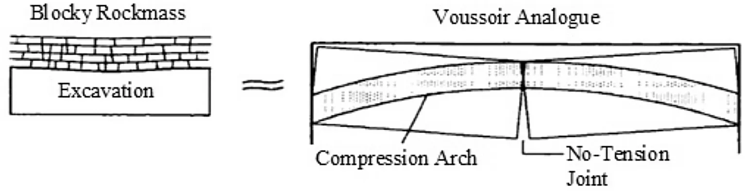
Fig.1. Voussoir beam analogy (Diederichs, 2000).
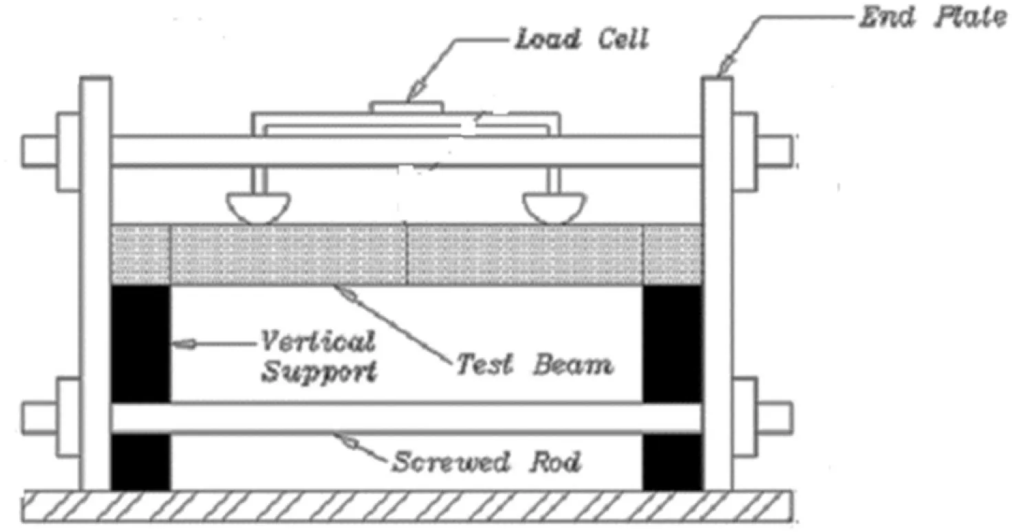
Fig. 2. Constraining frame.
Wright (1974) physically and numerically simulated cracked roof beams using limestone blocks and masonry bricks.From these results, the equations were derived describing the thrust, the deflection, and the maximum stress generated by the beam.Considering beams with cracks only at the abutment and midspan,he examined the effects of having multiple cracks throughout the beam. He showed that the worst case of a cracked beam, causing the maximum stress concentration,is a beam that is cracked at the abutments and midspan only.Furthermore,Wright(1974)’s results indicated that the assumptions made in Evans (1941)’s approach,n0.5 and the extent of the compression zones(nt)were the same at the abutments and midspan, were incorrect. His results also indicated that the shape of the stress distributions acting at the abutments and midspan are not triangular; however, the stress distributions do seem to approach a triangular shape in beams with high span/depth ratios.
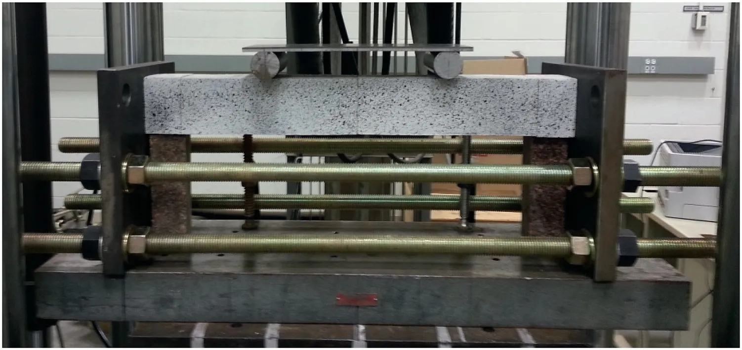
Fig. 3. Two-point load-spreading system.
Sterling (1977) carried out both analytical and experimental analyses of voussoir beams.His analytical work involved examining six different shapes for the stress distribution acting upon the abutments and midspan.In all the cases,he assumed that the depth of stress distribution at abutment was equal to it at midspan, i.e.nN. Based on laboratory testing of a model of cracked beams,Sterling (1977) concluded that the assumption of a rectangular stress distribution agreed more closely with his experimental results.
Stimpson and Ahmed(1992)conducted physical testing on thick intact rock beams(i.e.the beams were not fractured)of limestone,granite and potash with span/depth ratios less than 5. These physical tests revealed a progressive failure mechanism dominated by tensile fracturing. This failure mechanism is characterized by three distinct stages. Stage I, the primary beam stage, terminates with the initiation of tensile cracking in the lower fibres at the midspan. This stage also marks the initiation of linear arching. As loading continues following midspan cracking,two diagonal cracks initiate and propagate very rapidly towards each abutment. Their development marks the end of stage II. Continued loading beyond the stage of diagonal cracking marks stage III. This stage is characterized by the ultimate failure of the rock beam which occurs either by the shearing of the rock above the diagonal crack or shearing along the diagonal crack. This shear failure mode, in the authors’ opinion, is caused by the large axial forces developed in the arch, which causes the shear strength of the rock to be exceeded. Stimpson and Ahmed (1992) also conducted a discrete crack propagation using finite element analysis for a typical intact rock beam. The results validated the progressive failure mechanism observed in the laboratory testing.
Mottahed and Ran (1995) performed both physical and finite element testing. The physical tests involved voussoir beams cut from two types of Durox bricks of lightweight concrete.Because the lightweight concrete has low values of Young’s modulus and compressive strength, the model beams failed at low transverse loads so that the horizontal movement of both abutments was negligible;therefore,the abutments were assumed to be rigid.This assumption, under which the tests were conducted, is valid;however,in reality,some small abutment movement occurs.Under the experimental conditions, almost all the model voussoir beams failed by crushing at the high stress areas located at the ends and midspan.The finite element approach considered triangular stress distributions acting at the midspan and abutments, and the depth of these distributions were assumed to be equal on both sides, i.e.nN. The results showed that a linear analysis of the structure is inappropriate for describing the beam behaviour. Based on these conclusions,equations were therefore derived for the thrust,lever arm, centroid location, and crushing strength using nonlinear analysis.
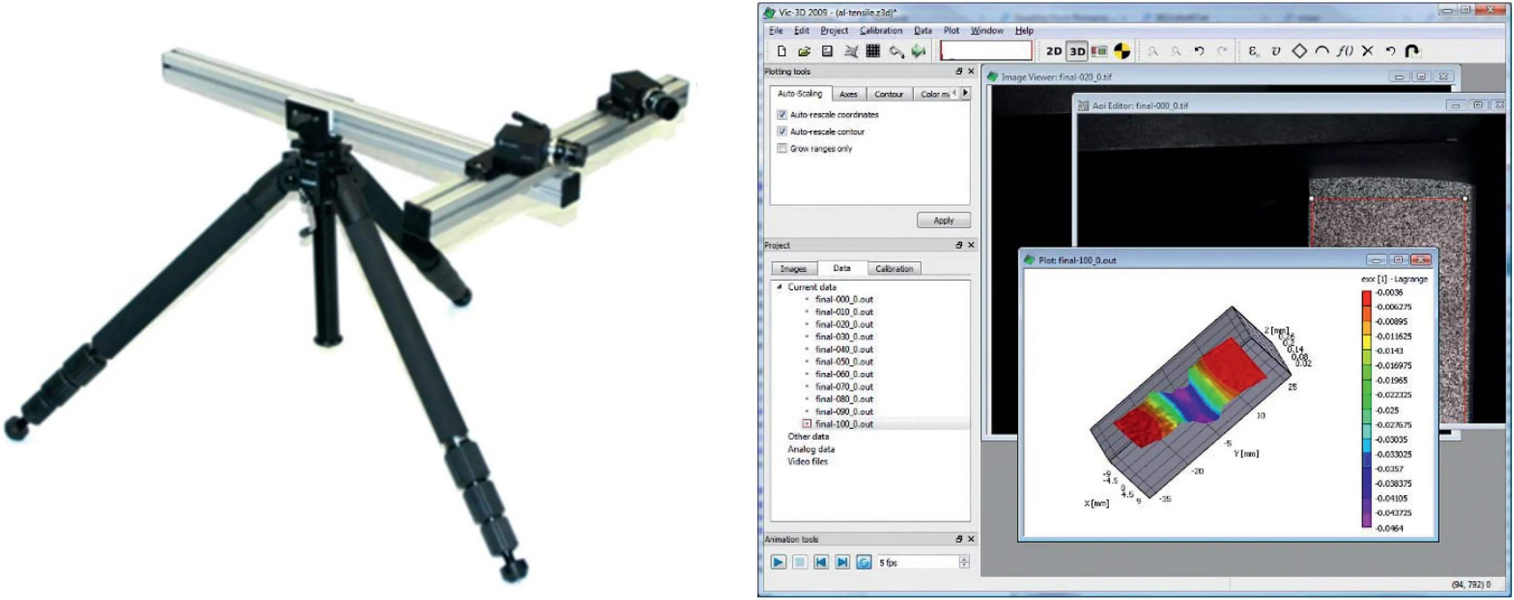
Fig. 4. Vic-3D DIC system: The cameras (left) and the image processing software Vic-3D (right).
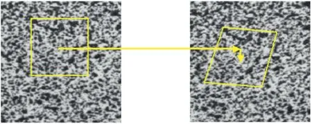
Fig. 5. Undeformed and deformed images with subset.
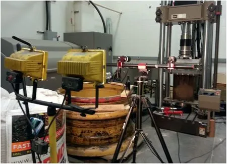
Fig. 6. Experimental set-up.
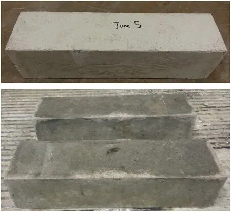
Fig. 7. Plaster beam (upper) and concrete beams (lower).
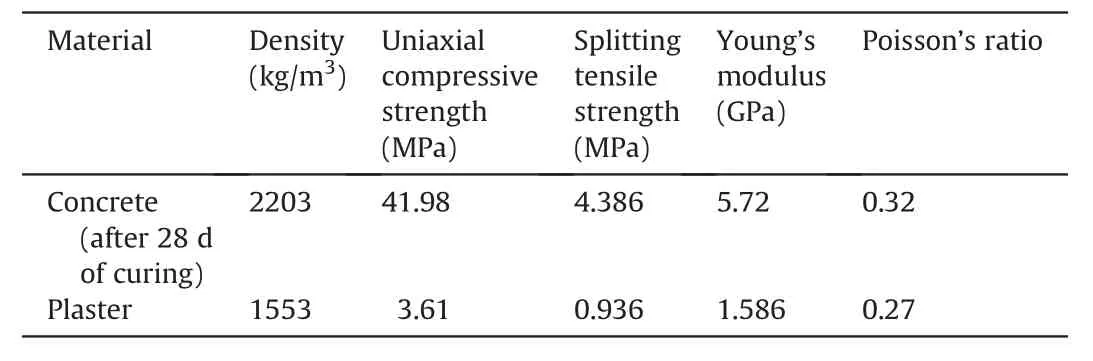
Table 1Properties of experimental samples.
Talesnick et al.(2007)studied the behaviour of voussoir beams comprised of six plaster blocks using a centrifuge test. Voussoir beam models of two different geometries were investigated.While both have the same length and width,one has half the thickness of the other.Displacements at the ends of each block were monitored by 12 linear variable differential transformer (LVDTs), and three pairs of strain gauges were used to measure the strain developing at the top, middle, and bottom of one of the blocks. Thrust was monitored by a load cell at the end. The model was subjected to accelerations of up to 90g. It was found that small rotation and displacement of the block near the abutment were required in order to set up a stable linear arch.Based on the two models tested,the thrust developed was independent of beam thickness. The depth of the strain distribution ranged from the whole thickness of the beam near the abutment to half of the beam thickness near the midspan.
Yang and Shang (2007) modelled the voussoir beam using plaster blocks. Stress sensor was used to monitor the horizontal thrust during the test, and the initial constraining stress was applied by tightening the nut and measured by stress sensor as well. The span/depth ratio and the initial constraining stress were found to affect the behaviour of the moment arm and the horizontal stress in the voussoir beam. The stress distribution was not investigated.
Based on the above literature review, a number of questions emerge with respect to assumptions about the stress distribution size and shape that lead to incompatibilities between results obtained by different investigators. All the analyses, except for Sterling(1977)’s,assumed triangular-shaped stress distributions of equal size acting at the abutment and midspan. Sterling (1977)dealt with six different stress distribution shapes, of which the rectangular-shaped stress block, which had equal depth at the abutment and midspan,gave the best fit to his experimental data.Nevertheless, Wright (1974)’s results indicated that Sterling(1977)’s finding in this case was incorrect. His results indicated that the induced lateral stresses, developed at the abutments and midspan,increase in a nonlinear manner and that the depths over which they act are not equal. Mottahed and Ran (1995) did not identify where crushing first occurred.They believed that crushing occurs first at the abutments.As the beam deflects,the compressive stresses generated are being concentrated more at the ends than at the centre. Consequently, the maximum stress generated at the ends is greater than that at the centre.

Fig. 8. Two-block voussoir beam consisting of painted plaster samples.
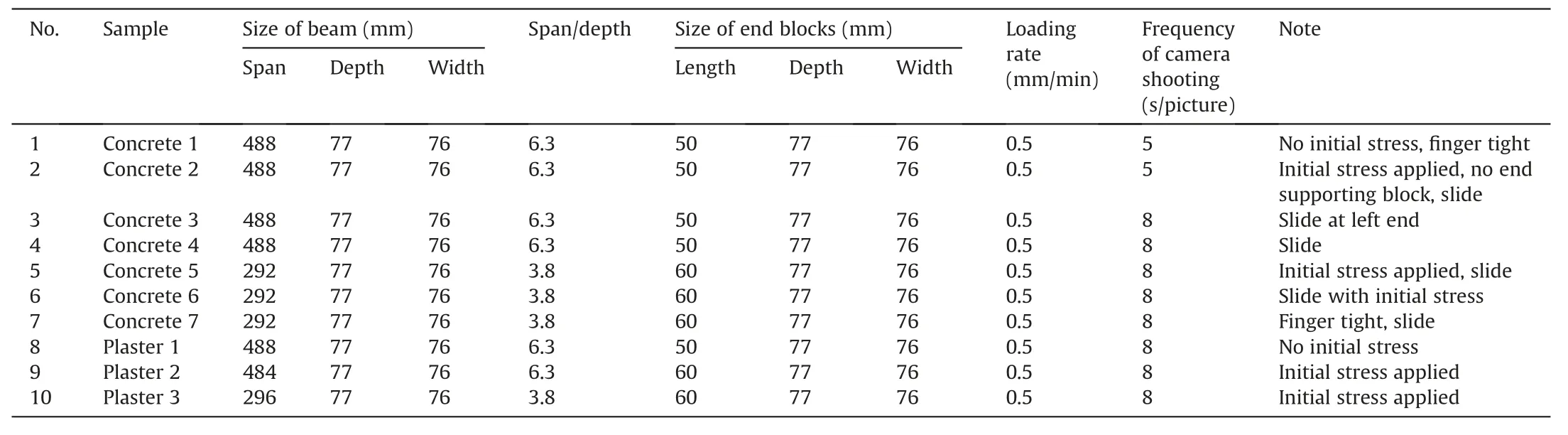
Table 2Summary of the tests conducted.
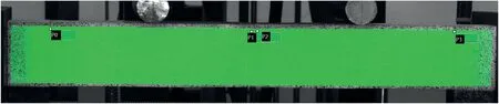
Fig. 9. Four points selected to monitor the deflection of concrete 1.
In reality, the stress distribution along the boundary is not necessarily linear, and experimental studies are necessary to determine its exact geometry (Tsesarsky and Talesnick, 2007).Based on the review of the experimental investigations, no test results were able to give the stress distributions at the abutments and midspan as either the beam tested was an intact beam or the instruments used were limited.In this paper,a series of two-block voussoir beams were tested. The displacement and strain distributions at midspan and abutment were measured by Vic-3D digital image correlation (DIC) system.
2. Physical investigation
A series of tests was performed to investigate the behaviour of a two-block voussoir beam under transverse loading;two of the tests were explained below.The objectives of this series of tests were:(1)to investigate the behaviour of voussoir beams;and(2)to calibrate the numerical model for further investigation using the results from these tests.
Fig.10. Loadedeflection relationship for concrete 1.
2.1. Testing apparatus
The testing apparatus consists of a constraining frame, loading system, and Vic-3D correlation system which will be discussed in detail in the following sections.
2.1.1. Constraining frame
The constraining frame consists of two end-plates of 25 mm in thickness,which was connected via four screwed rods of 30 mm in diameter, as shown in Fig. 2. The vertical supports of the two abutment blocks are two limestone blocks.
2.1.2. Loading system
The load was applied by a servo-controlled loading frame,and a two-point load-spreading system was used, as shown in Fig. 3.
2.1.3. Vic-3D correlation system
The displacement and deformation on the beam surface were measured by the Vic-3D DIC system, as shown in Fig. 4. Photogrammetric analysis provided insights into the response of the rock mass during application of transverse loading and assisted in identifying the failure path that occurred. The Vic-3D correlation system tracked the deformation of the subset, as shown in Fig. 5.Only information at the centre of the subset will be output after processing.In these tests,subset size suggested by the software was 3535 pixels.The cameras used had a resolution of 20482048 pixels.
Table 3Characteristics of the two images selected.
In typical set-up, the Vic-3D DIC system can see an in-plane displacement accuracy of 1/50,000 of the field of view. This means that if a 1-m area is imaged,a 20-mm motion can be detected(Correlated Solutions, 2010). The final set-up is shown in Fig. 6.
2.2. Beam sample
From the literature review, three materials were considered:concrete,plaster and sulfaset.Since the sulfaset provider could not be contacted,only concrete and plaster samples were made for the tests, as shown in Fig. 7.
The properties of the plaster and concrete samples are detailed in Table 1. The Poisson’s ratio may be less accurate than other pa-rameters because the instrument for transverse displacement measurement slightly pierced into the cylinder samples during the test.
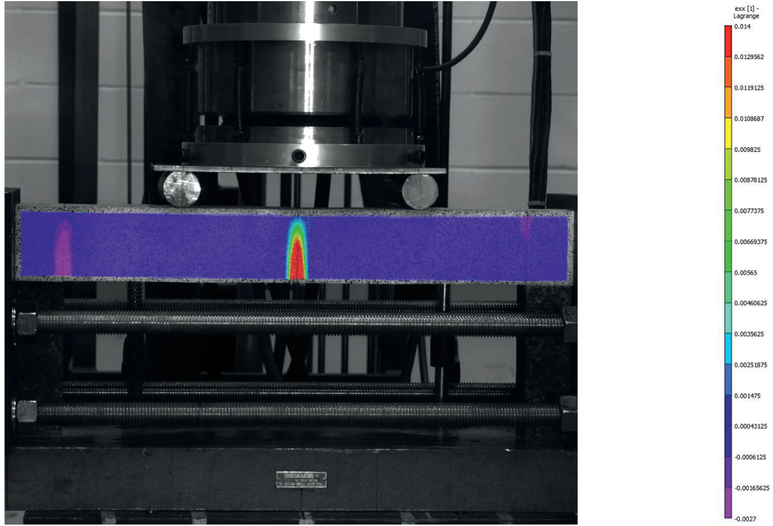
Fig.12. Strain εxx contour of the image concrete 1-033.
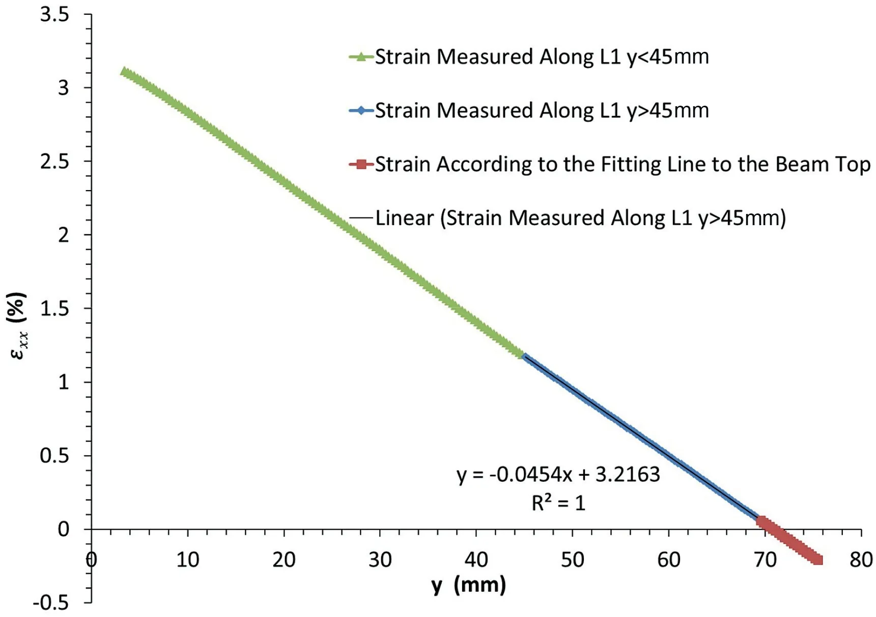
Fig.13. Strain along line L1 at the midspan of image concrete 1-033.
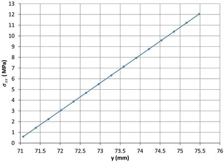
Fig.14. Compressive stress distribution along line L1 at the midspan of image concrete 1-033.
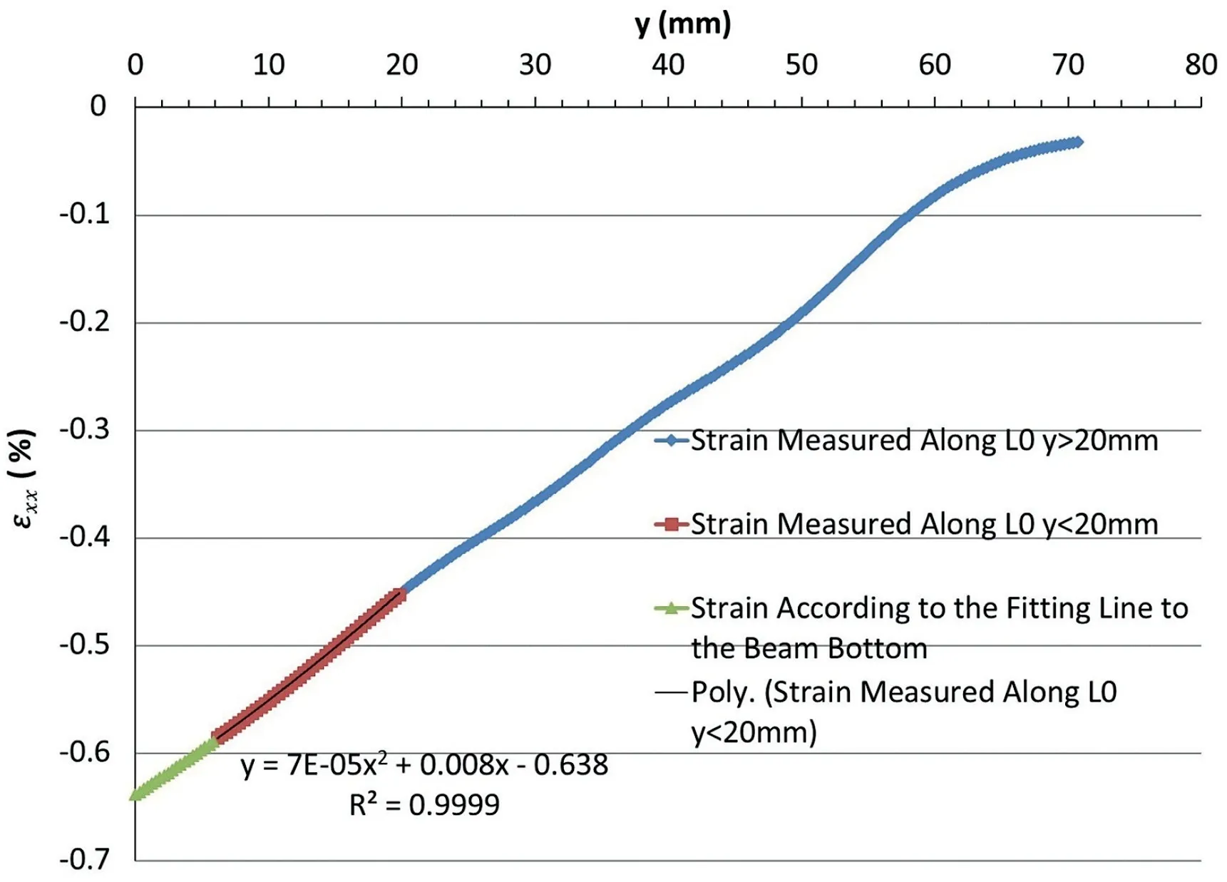
Fig.15. Strain along line L0 at the abutment of image concrete 1-033.
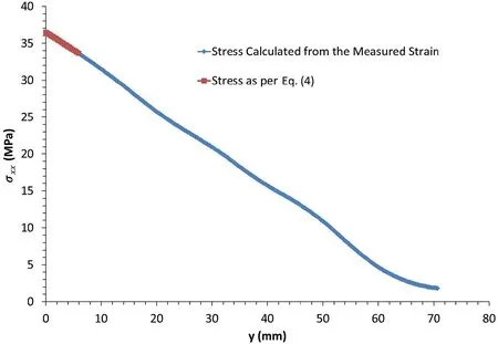
Fig.16. Stress distribution at the abutment of image concrete 1-033.
In order to be tracked by the Vic-3D DIC system, the front surface of the beam was painted with black speckles on a white background(see Fig.8).All of the tests performed are summarised in Table 2.
2.3. Typical behaviour of voussoir beam test
The concrete 1 and plaster 1 in Table 2 were selected to describe the behaviour of a concrete voussoir beam and a plaster voussoir beam, respectively, during the test.
2.3.1. Typical behaviour of concrete voussoir beams
(1) Loadedeflection relationship.Four points on the beam’s front surface were selected to monitor the displacement of the beam(see Fig. 9). To detect sliding at the abutment, pointsP0 andP3 were selected. These will detect the slide at both sides of the voussoir beam near the abutments. The deflection at the centre was measured at pointsP1 andP2, located at the left block and right block near the centre, respectively.
The loadedeflection relationship is shown in Fig. 10. The load was applied by the MTS loading frame controlled in specified speed of 0.5 mm/min. Five deflections were presented. The load-MTS deflection gave the full failure path of voussoir beam tested. As the tracking of monitoring points was lost after large deformation occurred,the other four deflections did not cover the whole failure path. The load vs.P1 andP2 average deflection gave the relationship between the load and the defection at the centre of voussoir beam. The load vs.P0 andP3 average defection gave the relationship between the load and slide induced at the abutment. The relationships between the load and deflection of MTS and deflection at centre of voussoir beam with slide deducted were presented as well.
(2) Stress distributions at the midspan and abutment.In the linear range for load-deflection of the beam behaviour, two images were selected for analysing the stress distributions at the abutment and midspan of the voussoir model under transverse load. The parameters of the images are presented in Table 3.
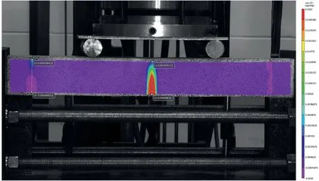
Fig.17. Horizontal strain εxx contour of the image concrete 1-040.
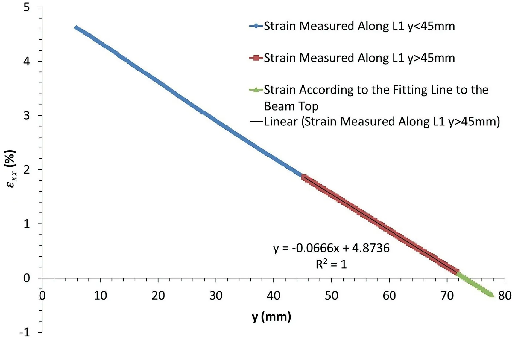
Fig.18. Strain along the line L1 at the midspan of image concrete 1-040.

Fig.19. Strain along the line L0 at the abutment of image concrete 1-040.
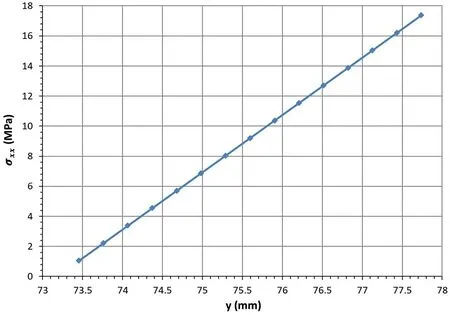
Fig.20. Compressive stress along the line L1 at the midspan of image concrete 1-040.
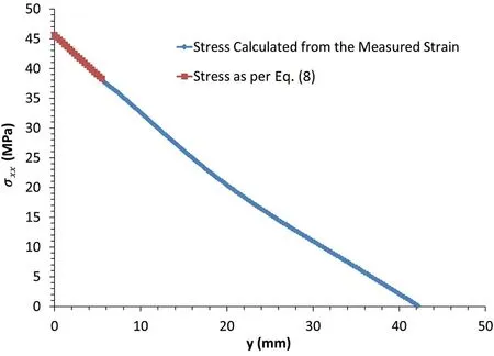
Fig.21. Stress distribution along the line L0 at the abutment of image concrete 1-040.
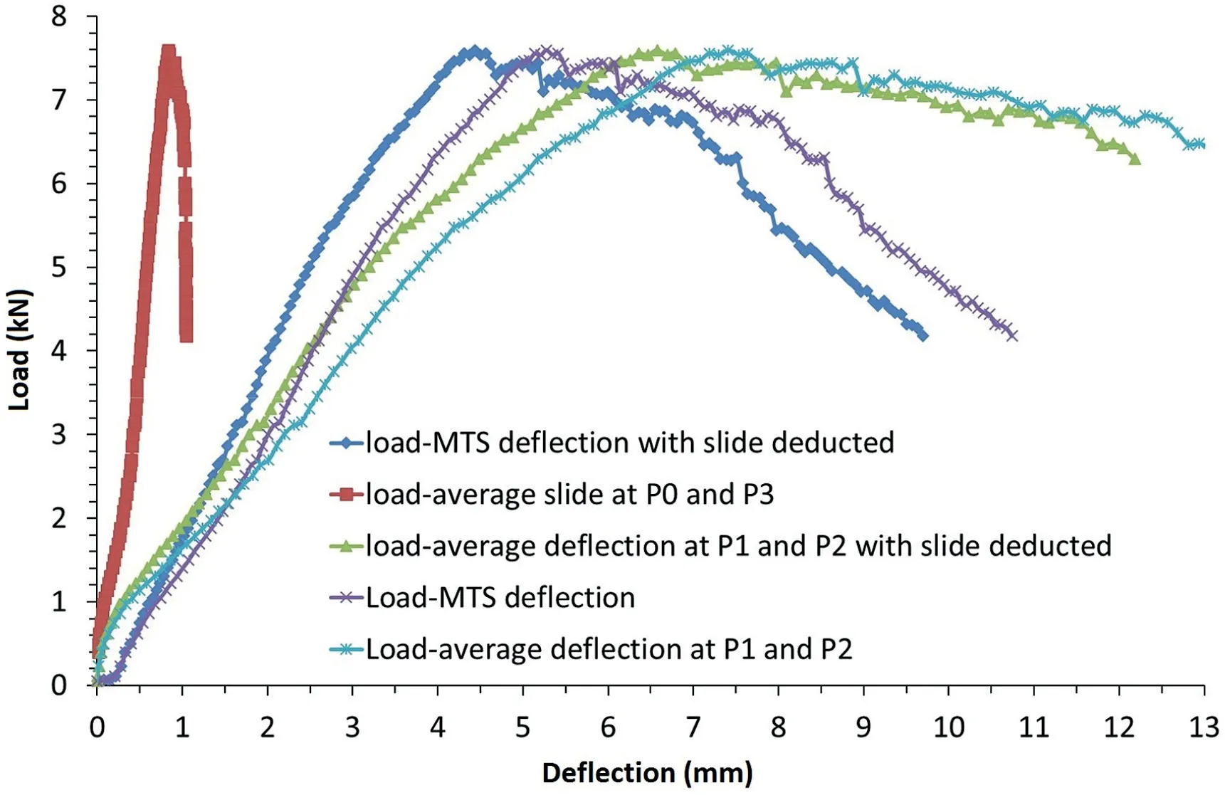
Fig. 22. Loadedeflection relationship for plaster 1.
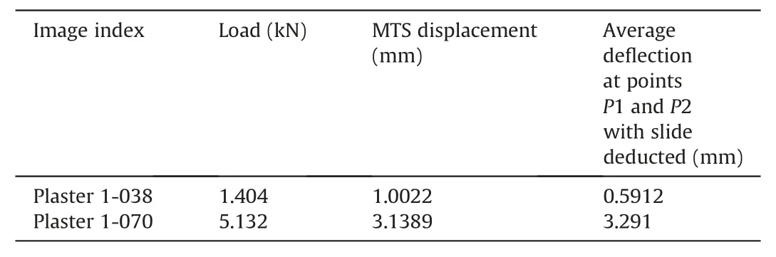
Table 4Characteristics of the two images selected.
Two lines,L0 andL1,were drawn at the abutment and midspan,respectively, to extract the strain along the two lines, as shown in Fig.11.
It is observed that the area near the edges of the front surface is not covered by the contour in Fig.11.This is a result of the principles of Vic-3D DIC system and also the limitations of camera resolution.The depth of the uncovered area was nearly 5 mm from the horizontal edges,which was around 7%of the depth of the front surface of the beam. This made the deformation at the very top and very bottom of the beam unknown.This lost area was of high interest.At this stage, the strain of this area was approximated by the trend line.
In this study, the positive strain is tension, and the negative strain is compression. The positive stress is compression.
(a) Image concrete 1-033.The contour of the horizontal strain εxxis shown in Fig. 12. As the deformation at the very top and very bottom of the surface is unknown,a fitting method is used to find the strain distribution in this area.
The strain measured along lineL1 at the midspan is shown in Fig. 13. There is a linear relationship between the strain and the beam thickness at the upper part of the beam, as shown in following equation withR21:

whereyis the thickness of the beam at the midspan.
Fig.13 shows that the strain is in compression wheny>70:84 mm, and the thickness of the beam or the length of lineL1 ist75.48 mm.Therefore,the ratio of the compression zone depth to the beam thickness at the midspan isN0.0614.
From the compressive strain in Fig.13 and the Young’s modulus of the concrete sample in Table 1, the compressive stress at the midspan is calculated, as shown in Fig.14. From Eq. (1), the equation for stress distribution along lineL1 at the midspan is

The strain measured along lineL0 at the abutment is shown in Fig.15.Wheny<20 mm,the best fitting relationship between the strain and the beam thickness is written as follows, withR20:9999:

Fig.15 shows that the compression zone is extended over the whole depth of the beam.The ratio of the compression zone to the beam thickness at the abutment isn1. Further investigation is needed to determine whether this is a consequence of the experiment set-up.
The stress distribution at the abutment is shown in Fig. 16.Similarly, the stress distribution at the lower abutment is
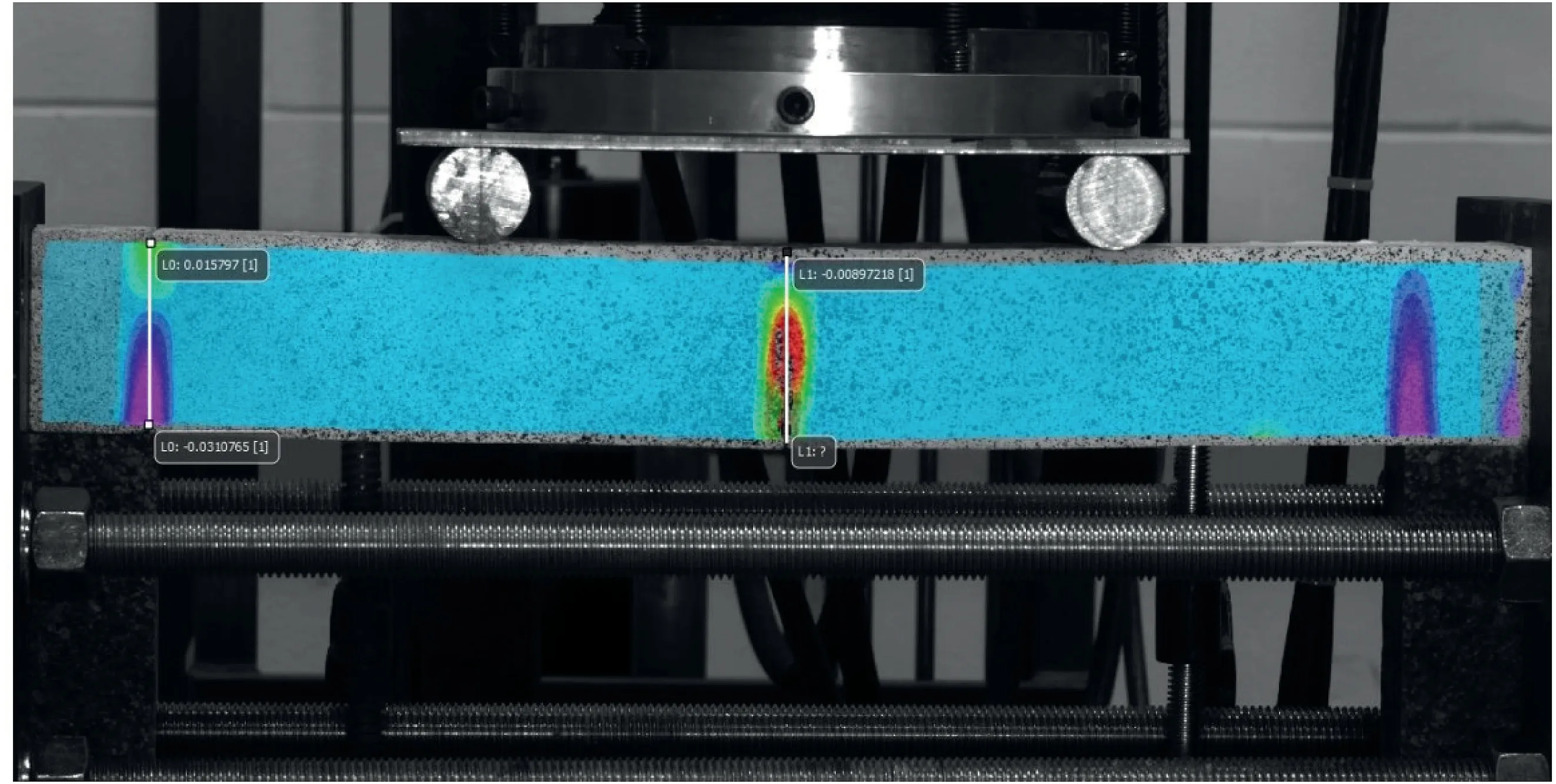
Fig. 23. Two lines drawn at the abutment and midspan for strain extraction of plaster 1.
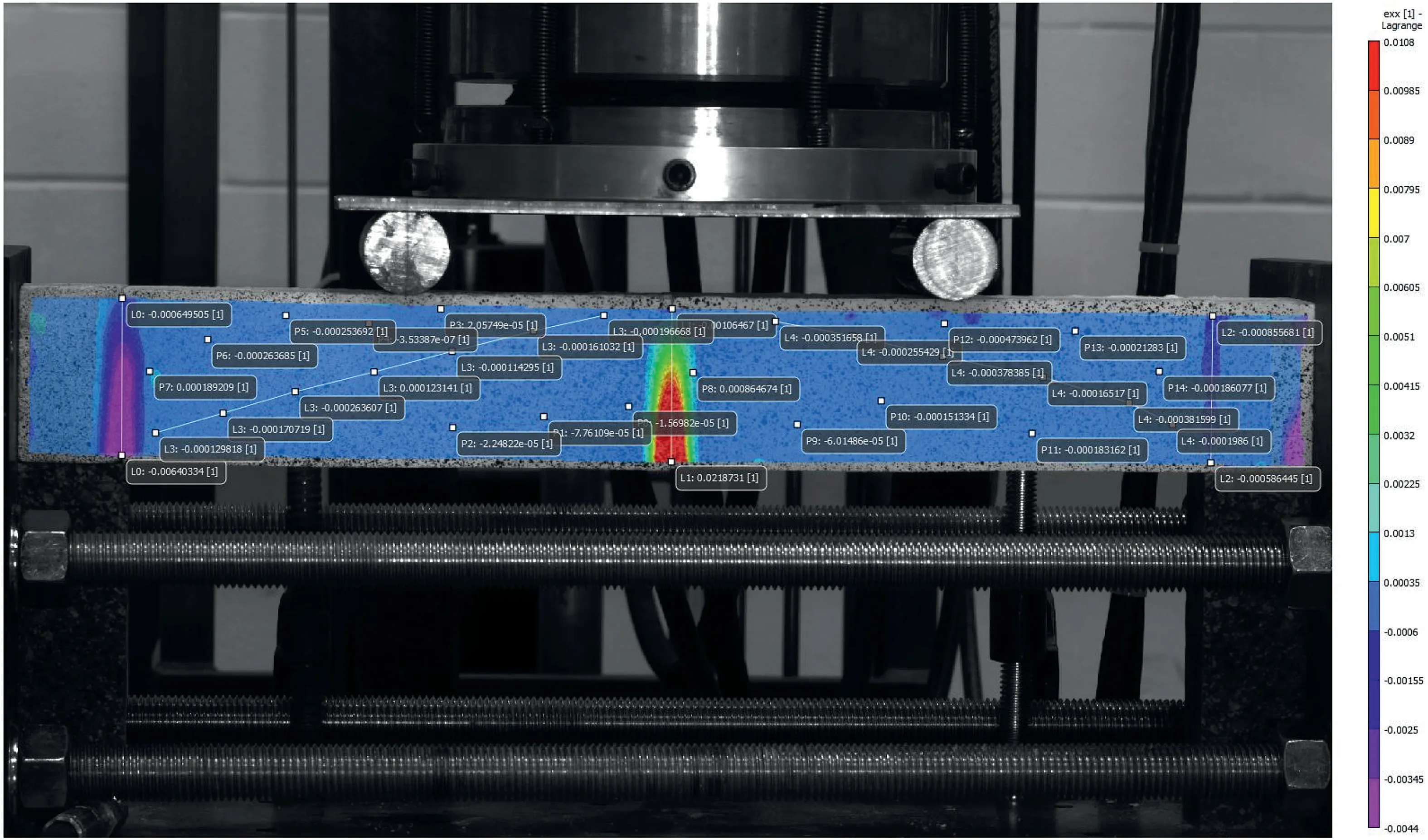
Fig. 24. Strain εxx contour of the image plaster 1-038.
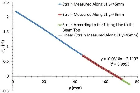
Fig. 25. Strain along the line L1 at the midspan of image plaster 1-038.
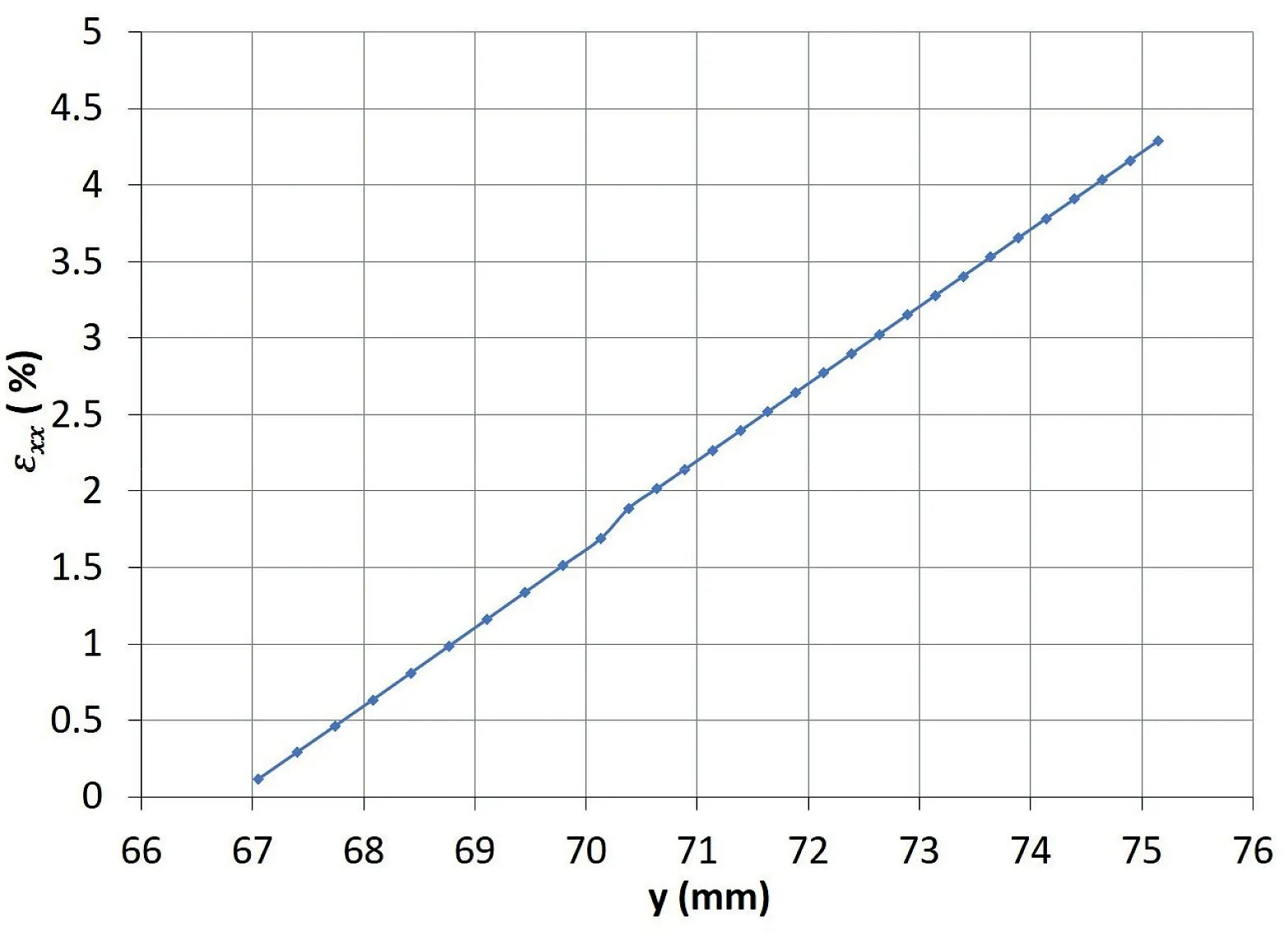
Fig. 26. Compressive stress along the line L1 at the midspan of image plaster 1-038.

(b) Image concrete 1-040.Similarly,the image concrete 1-040 was analysed in the same way as that for image concrete 1-033. The contour of horizontal strain of image concrete 1-040 is shown in Fig.17. The strain along the midspan and abutment was extracted and is presented in Figs.18 and 19, respectively. With the Young’s modulus known, the stress distribution along midspan and abutment was obtained and is shown in Figs. 20 and 21, respectively.
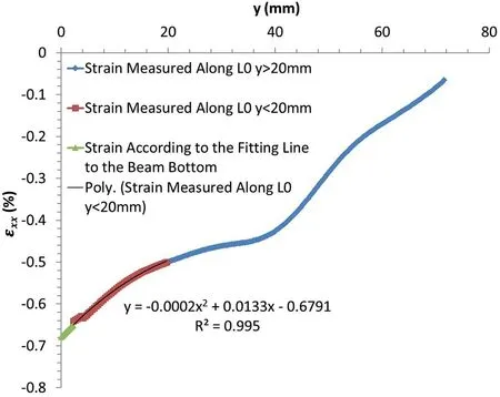
Fig. 27. Strain along the line L0 at the abutment of image plaster 1-038. The stress calculated along the line L0 at the lower abutment is shown in Fig. 28 and fitted by following equation, with t 76.16 and n 1.
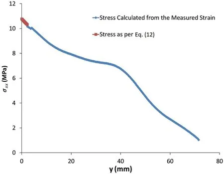
Fig. 28. Stress distribution along the line L0 at the abutment of image plaster 1-038.
The strain along the lineL1 at the upper midspan can be represented by the following linear equation, withR21:

The strain along the lineL0 at the lower abutment can be represented by following polynomial equation,withR20.9998:

The stress along the lineL1 at the upper midspan is obtained as follows, witht77.7386 andN0:0586:

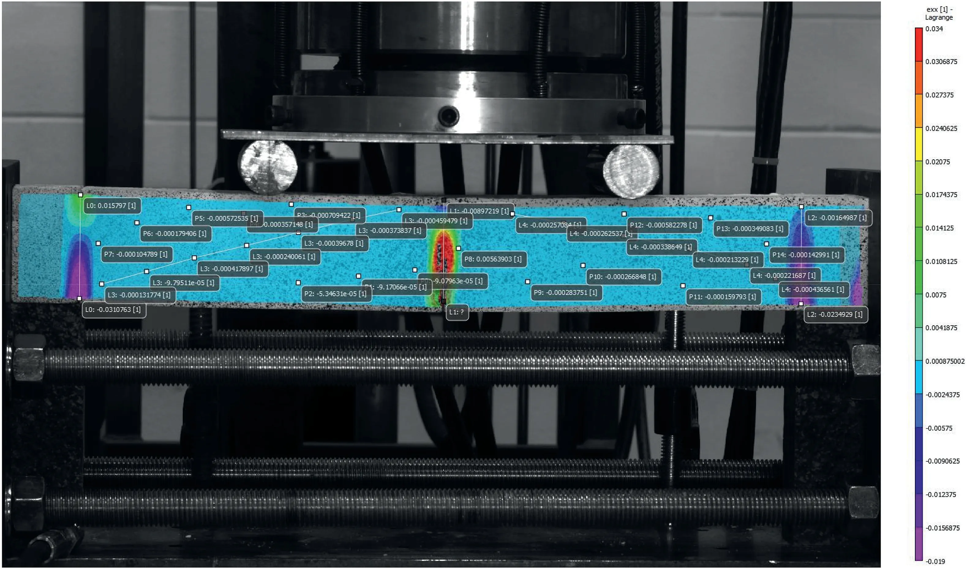
Fig. 29. Strain εxx contour of the image plaster 1-070.
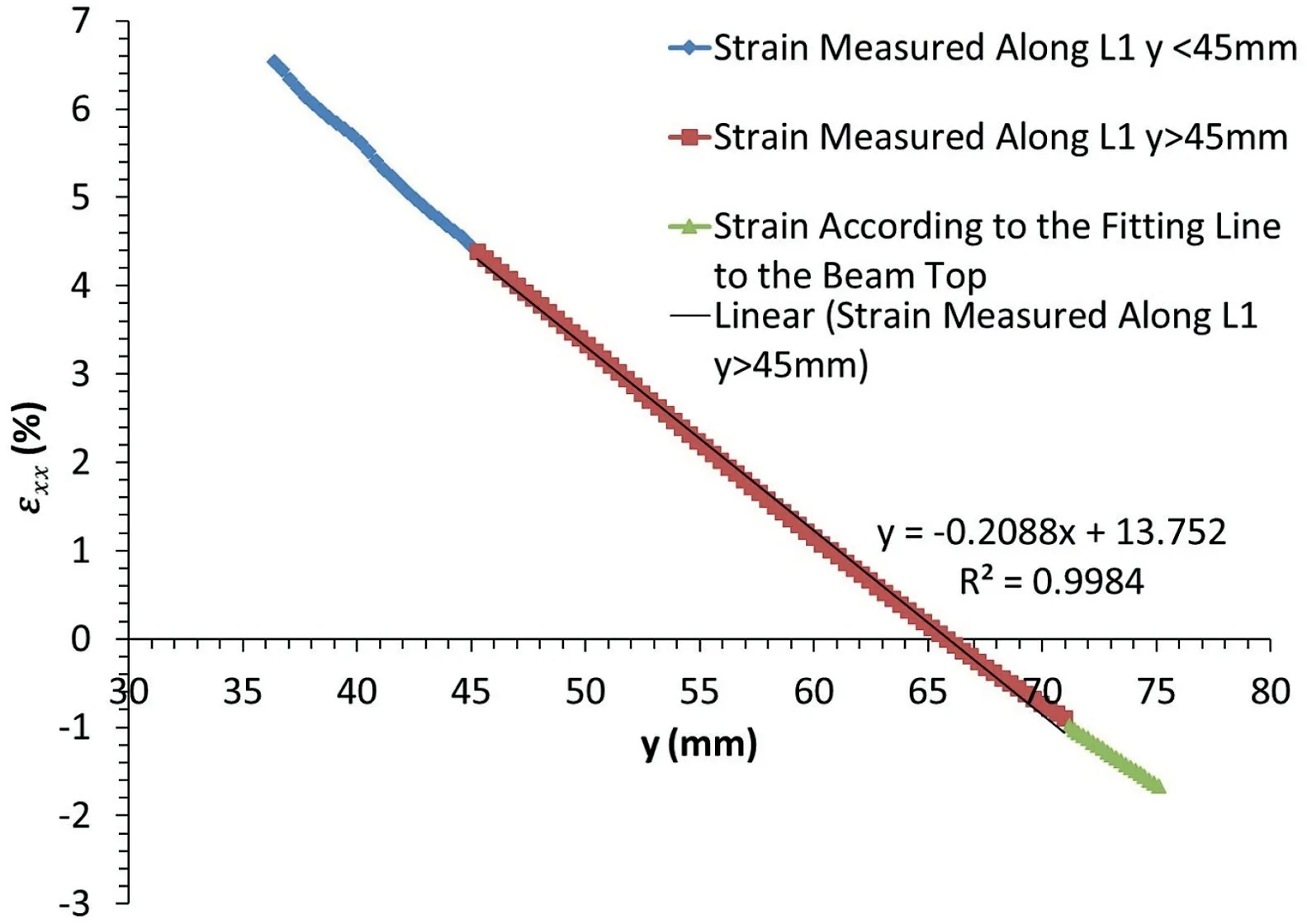
Fig.30. Strain along the line L1 at the midspan of image plaster 1-070.The strain along the line L1 at the upper midspan can be fitted as follows, with R2 0.9984.
The stress along the lineL0 at the lower abutment is obtained as follows, witht76:106 andN0:5536:

2.3.2. Typical behaviour of plaster voussoir beams
Plaster 1 in Table 2 is selected to show the behaviour of plaster voussoir beams. The following analysis is similar to the one performed for the concrete voussoir beam above.
(1) Loadedeflection relationship.Similarly, four points were selected to track the displacement at abutment and midspan of the voussoir beam, as shown in Fig. 9. The loadedisplacement relationship is presented in Fig. 22.
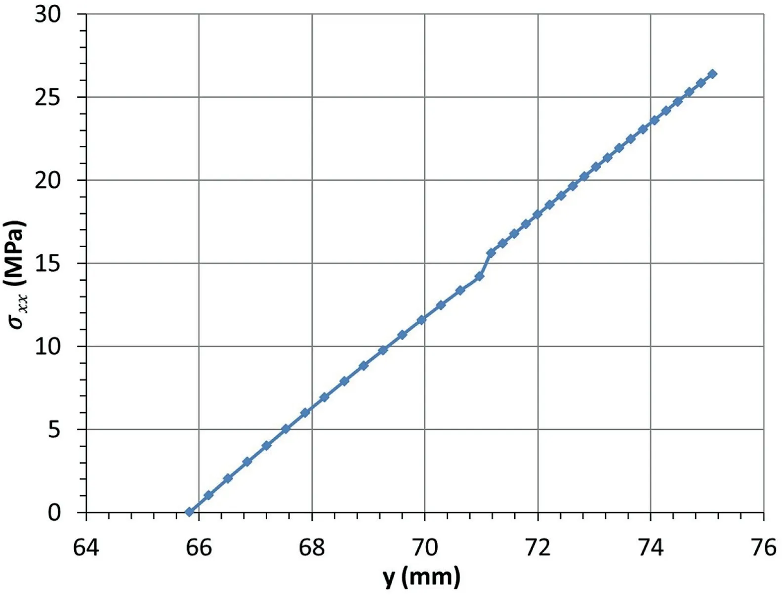
Fig. 31. Compressive stress along the line L1 at the midspan of image plaster 1-070.The strain along the line L0 at the lower abutment is shown in Fig.32 and fitted by the following equation, with R2 0.9998.
(2) Stress distributions at the midspan and abutment.Within the linear range of loadedeflection relationship, two images, image plaster 1-038 and image plaster 1-070, were selected to investigate the stress distribution characterises at midspan and abutment.The load and displacement of the two images are presented in Table 4.
The two lines,L1 andL0, to extract the strain distribution at midspan and abutment are shown in Fig. 23. This image is the contour of the horizontal strain of image plaster 1-070.
(a) Image plaster 1-038.The contour of the horizontal strain εxxis shown in Fig.24,which shows that it is under compression over the whole beam thickness between the midspan and abutment.
The strain along the midspan was extracted and is shown in Fig. 25. The strain along the lineL1 at the upper midspan can be fitted by a linear equation, withR20:99:

With the Young’s modulus, the stress at the midspan was obtained by Eq. (10), witht75.145 andN0.1131. The stress distribution at the upper part of midspan is shown in Fig.26.

Similarly,the strain along the abutment is shown in Fig.27 and fitted by following equation, withR20.995:
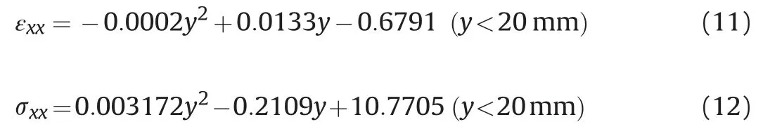
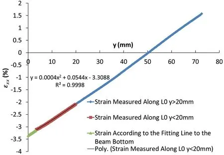
Fig. 32. Strain along the line L0 at the abutment of image plaster 1-070. The stress along the line L0 at the lower abutment is shown in Fig.33 and fitted by the following equation, with t 75.09 and n 0.666.
Fig. 33. Stress distribution along the line L0 at the abutment of image plaster 1-070.
(b) Image plaster 1-070.The contour of the horizontal strain εxxis shown in Fig.29.The strain along the midspan was extracted and is shown in Fig. 30.

The stress along the lineL1 at the upper midspan is shown in Fig. 31 and fitted by following equation, witht75.0984 andN0.1234:

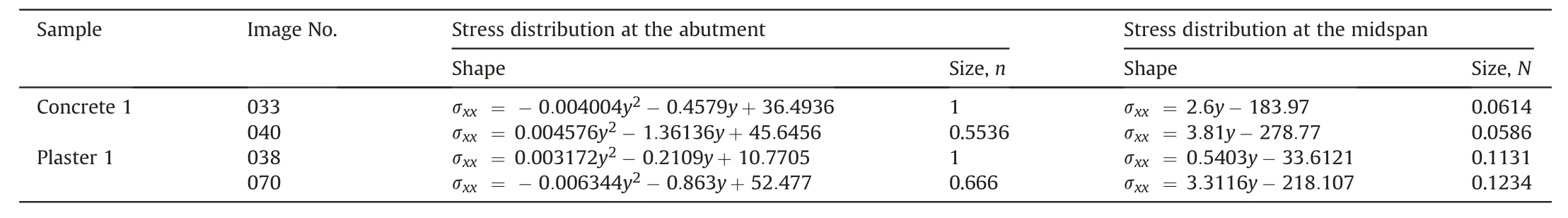
Table 5Summary of the characteristics of stress distribution.
The strain along the lineL0 at the lower abutment is shown in Fig. 32 and fitted by the following equation, withR20.9998:

The stress along the lineL0 at the lower abutment is shown in Fig.33 and fitted bythe following equation,witht75.09 andn0.666:

3. Results and discussion
The characteristics of stressdistribution are summarised inTable 5.Fromthesephysicaltestsutilizingthephotogrammetricmeasures,itis firstly foundthatthe stressdistributions at the midspan and abutment are different both in shape and depth. The stress distribution is changing as the loading changes as well.These are different from the assumptions made in previous analyses. These findings should be included in the theoretical modelling of voussoir beams.
It is should be noted the strain measured including not only the strain in the beam body but also the displacement of the joints.This resulted in the relative large strain at the joints.
4. Conclusions
The findings are summarised as follows:
(1) The stress distribution at the midspan is best fitted by a linear function, and the extent of the distribution is much smaller than that at the abutment. The depth of the distribution changes with increasing loading.
(2) The stress distribution at the abutment is best fitted by a polynomial function, and the extent of the distribution is more than one half of the beam’s thickness.The distribution decreases rapidly with an increasing load.
(3) The maximum stress at the abutment is larger than that at the midspan.The first stress is nearly two times that of the lastone.
(4) The shear sliding failure at the abutments is likely to occur with the voussoir beams of high strength and low span/thickness ratio. For stable voussoir beams, sliding also occurred at the beginning of the test, until it ceased at a certain stage. The load-bearing ability of the beam kept increasing at this time. This indicates the onset of stable arching after initial shearing.
(5) Except for the area near the top of the abutment, the whole beam is under axial compression. This means that the thickness of the arch developed is equal to the beam’s thickness.
Declaration of Competing Interest
The authors wish to confirm that there are no known conflicts of interests associated with this publication and there has been no significant financial support for this work that could have influenced its outcome.
 Journal of Rock Mechanics and Geotechnical Engineering2020年3期
- Journal of Rock Mechanics and Geotechnical Engineering的其它文章
- Crack initiation of granite under uniaxial compression tests: A comparison study
- Reliability analysis of slopes considering spatial variability of soil properties based on efficiently identified representative slip surfaces
- Critical state model for structured soil
- Coupled hydro-mechanical analysis of expansive soils: Parametric identification and calibration
- A modified soil water content measurement technique using actively heated fiber optic sensor
- Benchmark solutions of large-strain cavity contraction for deep tunnel convergence in geomaterials