
Numerical research on effect of overlap ratio on thermal-stress behaviors of the high-speed laser cladding coating*
2021-01-21 02:15:38XiaoxiQiao喬小溪TonglingXia夏同領(lǐng)andPingChen陳平
Chinese Physics B 2021年1期
Xiaoxi Qiao(喬小溪), Tongling Xia(夏同領(lǐng)), and Ping Chen(陳平)
School of Mechanical Engineering,University of Science and Technology Beijing,Beijing 100083,China
Keywords: high-speed laser cladding,overlap ratio,thermal-stress evolution,residual stress and deformation,numerical simulation
1. Introduction
Laser cladding is a kind of surface modification technology,which is widely used in the fields of aerospace,automobile, petroleum, and so on. It utilizes a high-energy-density laser beam to melt the alloy power and form a cladding layer metallurgically bonded to the metallic substrate. The cladding coating has the advantages of low dilution ratio and good bond condition, which can significantly improve the anti-corrosion and wear resistance of the substrate surface.[1,2]However,due to the rapid heating and cooling phenomenon of the molten pool during laser cladding, and the difference in thermal expansion properties between the coating and the substrate, the cladding coating has obvious local plastic deformation and residual stress,which will easily lead to cracks and affect the fatigue life of the mechanical parts.[3–6]Therefore, it is crucial to study the thermal-stress evolution, residual stress, and deformation of laser cladding coating.
The laser cladding process involves complex physical phenomena,such as metallurgy,phase transformation,molten pool expansion, and solidification shrinkage.[7–11]For the multi-track laser cladding coating, its temperature and stress evolution processes are even more complicated. Due to the limitation of experimental methods,[12]the numerical method is widely adopted for its advantages in obtaining the thermalstress evolution and the three-dimensional distribution of residual stress and deformation, which can help to reveal the generation mechanism of residual stress and deformation, as well as the high-risk area caused by the residual stress concentration.
Residual stress is influenced by the scan speed, power,overlap ratio, etc.[13–15]So far, researchers have done many numerical simulations on the thermal-mechanical evolution during the laser cladding process. The models of powder flow and molten pool flow fields are improved to study the complex physical phenomena of laser cladding.[16–20]Farahmand et al.[15]established a numerical model to study the multitrack laser cladding process with an overlap ratio of 25%.Results show that the residual stress is high at the interface of the cladding coating and substrate, where it has a high crack tendency. Sun et al.[21]developed a numerical model with an overlap ratio of 33% to study Ni60A coatings, and found that the longitudinal residual stress(LRS)increased the crack susceptibility. Chew et al.[22]developed a 3D numerical model with an overlap ratio of 50% to investigate the residual stress for the laser cladding of AISI 4340 steel powder onto a similar substrate material.Results indicated that the deposited cladding layer could reduce the tensile residual stress of the previous track cladding coating,and the resulting local stress peak may damage the fatigue performance. Ghorashi et al.[23]also analyzed the residual stress of the multi-track laser cladding process numerically and captured the stress relaxation and hardening phenomena.
In practical industrial applications, due to the limitation of the width and thickness of single-track laser cladding coating, multi-track laser cladding coating is used to cover the whole work surface and to improve its corrosion resistance and wear resistance. In the multi-track laser cladding process, the overlap ratio is an important parameter, which will directly affect the quality of multi-track cladding coating.[24]Meanwhile, the corresponding thermal-stress evolution during the laser cladding process,the residual stress distribution,and residual deformation will be more complex;and the complex interactions between each track cladding layer, as well as between the cladding coating and the substrate cannot be neglected. Prasad et al.[25]found experimentally that increasing the overlap ratio can improve the wear resistance of the coating. Zhao et al.[26]studied the effects of overlap ratio on the mechanical property of YCF101 laser cladding coating, and results showed that overlap mode could improve the re-melting area, control the cracks and pores in the cladding coating,and refine the microstructure.
In the process of laser cladding, scanning speed is also an important parameter, which will affect the coating quality and cladding efficiency. Since 2013,Fraunhofer proposed the high-speed laser cladding technique first,[27,28]and it has gained wide attention. The high-speed laser cladding coating has the advantages of low dilution ratio,small surface roughness, few pores and inclusions, and small thickness, which is more suitable for industrial application.[29]However, during the process of high-speed laser cladding, the heating speed and solidification rate of the molten pool are much higher than those of the traditional cladding coating;thus,the”rapid heating and rapid cooling” phenomenon is more severe than that of the traditional cladding.
However,research on the influence of the overlap ratio on the thermal-mechanical behaviors of high-speed laser cladding coating is still lacking,and the mechanisms of heat accumulation and thermal deformation need further study.[30]In this paper, the thermal-stress evolution mechanism during the highspeed multi-track laser cladding process,as well as the effect rules of the overlap ratio on the thermal-stress evolution and the residual stress and deformation,are investigated.Section 2 introduces the experimental equipment and the laser cladding parameters. Section 3 introduces the numerical details, including control equation, material parameters, and boundary conditions, as well as the developed geometric model of the high-speed laser cladding coatings with overlap ratios of 10%,30%, and 50% based on the experimental results. Section 4 presents the results and discussion about the influence rules of the overlap ratio, mainly focusing on the thermal-stress evolution mechanism of the high-speed laser cladding,as well as the residual stress and deformation.
2. Experiment detail
An RF-J1500 laser cladding equipment is used to prepare the cladding coating,as shown in Fig.1(b). The device adopts a coaxial powder feeding mode,and the schematic diagram of the laser cladding coating process is shown in Fig.1(a).Argon is used as the carrier gas and protective gas. In our study,the cladding parameters used in the numerical simulations are the same as those in experiments. The laser power, scan speed,and feeding rate are 1200 W,25 mm/s,and 120 mg/s,respectively. And the overlap ratios used are 10%, 30%, and 50%.The powder and substrate materials are Ni60A nickel-based self-fluxing alloy and 316L stainless steel,respectively.
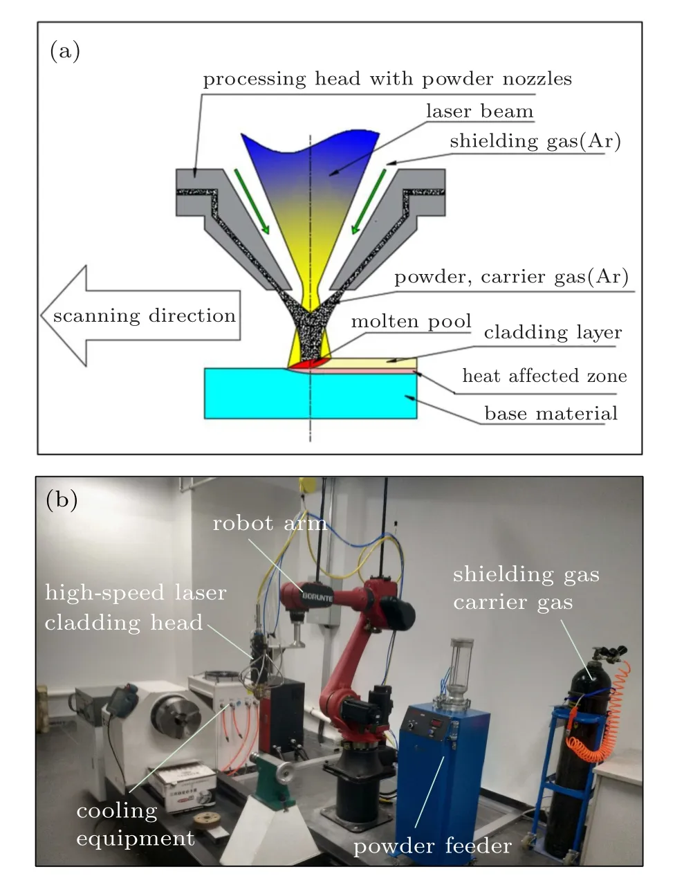
Fig. 1. (a) Schematic diagram of laser cladding. (b) High-speed laser cladding equipment.
3. Numerical simulation detail
3.1. Geometric model and meshing
The cross-section geometry of the high-speed laser cladding coating is different from that of the traditional lowspeed cladding coating. In the simulation, the geometric model of a single-track cladding coating is established based on the experimental result, as shown in Fig. 2(a). Since there is no dilution zone before laser cladding, the geometry model does not need to consider the shape of the dilution zone. The size of the substrate used in the study is 30mm×30mm×4mm, as shown in Fig. 2(b). In order to reduce the discontinuity of stress distribution caused by geometric end effects,[31]the length of the cladding coating in this study is 25 mm, which is slightly shorter than the length of the substrate. The laser scanning direction is defined as the Y-direction (i.e., longitudinal direction), and the vertical direction of laser scanning is defined as the X-direction (i.e.,transverse direction).
Three overlap ratios of 10%, 30%, and 50% are analyzed in this study, and the corresponding geometric model and mesh model are shown in Figs. 2(e)–2(g). And the track number used in the cladding is five. For the overlap ratio of 10%, its cross-section geometry has no obvious difference with that of the single-track coating due to the small overlapping area between each track coating. Then the geometric model is established, as shown in Fig. 2(e). When the overlap ratios are 30% or 50%, the interaction between each track coating is obvious. According to the coating thicknesses of 0.25 mm and 0.35 mm obtained experimentally,the geometric models established are shown in Figs.2(f)and 2(g).[22]
The mesh model adopted in the study is shown in Fig. 2(c). In order to improve the accuracy of numerical simulation, the meshes of the cladding coating and its adjacent substrate are encrypted (see Figs. 2(c), 2(e), 2(f), and 2(g)). Further, the grid independence is verified, and the results are shown in Fig. 2(d). According to change rules of the maximum temperature, the maximum stress and strain,and the calculating time varying with mesh number, Grid 3 is finally adopted, which can meet the calculation accuracy requirement. The minimum element size of grid 3 is 0.05mm×0.05mm×0.3mm,the relative error of molten pool temperature is less than 0.5%, and the relative error of maximum residual stress is less than 1.7%.
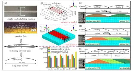
Fig. 2. Geometric and mesh models of highspeed laser cladding coating with overlap ratios of 10%, 30%, and 50%: (a) single-track coating geometry model,(b)the geometry model,and(c)the mesh model of the substrate and the multi-tracks coating,(d)mesh independence verification,and the geometric model and mesh model of the coating for overlap ratios of(e)10%,(f)30%,and(g)50%.
3.2. Material parameters
The substrate material used is 316L stainless steel, and its melting range is 1400?C–1460?C. The powder material is nickel-based self-fluxing alloy Ni60A,which has excellent corrosion resistance and wear resistance,and its melting range is 960–1040?C. To simplify the analysis, the solidification points of 316L and Ni60A are set to be 1400?C and 960?C,respectively,and the freezing point of 316L and Ni60A contact interface is assumed to be 1180?C.[14]That is to say,when the node temperatures of the substrate material,coating material,and the interface of the two materials are reduced to 1400?C,960?C,and 1180?C,respectively,the node can be regarded as solidified. Specific parameters, such as thermal conductivity,specific heat capacity, young’s modulus, yield strength, and density of the substrate and powder materials,can be found in the literatures.[21,32]
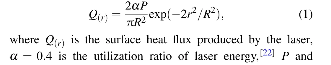
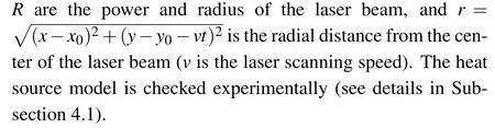
3.3. Laser heat source model
Gaussian heat source is used in our simulation, and the model equation is[18,33]
3.4. Heat conduction differential equation
In laser cladding,the heat conduction obeys Fourier law,and its partial differential equation is[3,18]
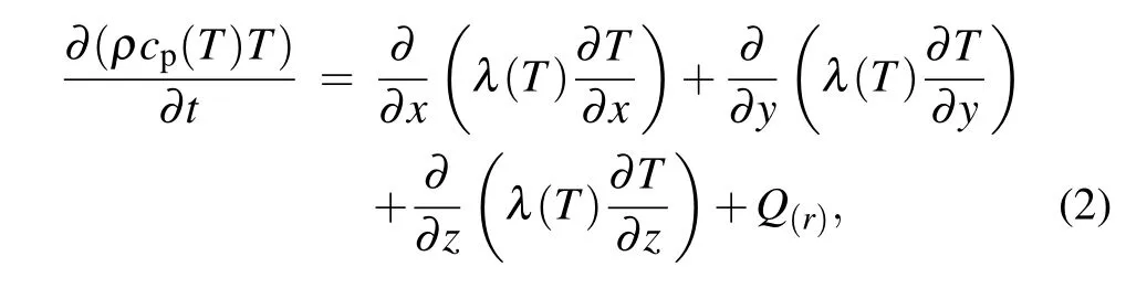
where ρ is the material density, cp(T) and λ(T) are the specific heat capacity and thermal conductivity varying with temperature T.
3.5. Boundary conditions
In the simulation,the initial thermal boundary conditions are
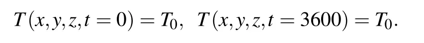
When t =3600 s, the substrate and cladding coating are regarded to be completely cooled down to the room temperature. In the laser cladding process, the energy loss mainly includes thermal conduction, thermal radiation, and thermal convection.Thus the relationship among them is defined as[15]

where n is the unit normal vector, ?T/?n is the derivative of temperature in n direction, and hcis the thermal convection coefficient, which is 80 W/m2·K[23]under the condition of forced convection between the carrier and protective gas.σ =5.67×10⁻⁸W/m2·K4is Stefan–Boltzmann constant. ε(0 <ε <1) is the emission coefficient, due to the relatively high radiation coefficient of the molten pool, ε =0.8 is used in this study.[34]Γ is the area affected by the laser beam. T is the surface temperature,and T0=20?C is the ambient temperature.
3.6. Thermal stress coupling analysis method
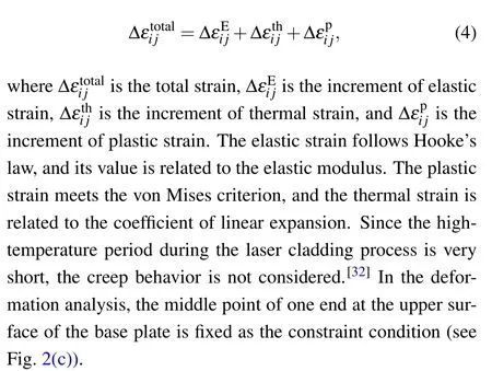
The indirect coupling method is adopted for the thermal analysis and stress analysis. Firstly, the temperature field of laser cladding is calculated, and then each step results of the transient temperature field are used as the input of the stress field model. The calculation of the mechanical stress is based on the thermo-elastoplastic model. The substrate material used is austenitic stainless steel,and most of the nickel-based corrosion-resistant alloys have austenitic structure, so the effect of phase transformation needs not to be considered.[35]In this study, elastic strain, thermal strain, and plastic strain are considered,and the total strain is[36,37]
In the simulation, the element activation method[38]is used. It means that the properties of the coating material are close to zero before the formation of the molten pool. When the temperature exceeds the material melting point,its thermal and mechanical properties are activated. In the laser cladding process, the laser beam not only interacted with the coating powder but also with the substrate,[39]as shown in Fig. 3.In other words, when the heat source passes, both the active cladding material and a part of the substrate surface absorb the laser energy at the same time. Figure 3(a)shows the area where the substrate directly interacts with the laser, and the corresponding thickness of the substrate interacting with laser energy is 0.05 mm. Figure 3(b) shows the energy absorption region.
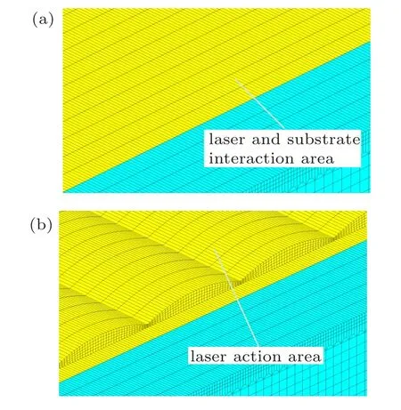
Fig.3. (a) The interaction area of laser and substrate. (b) The laser action area during the cladding process.
4. Results and discussion
4.1. Validation of heat source efficiency and temperature field
Due to the energy loss during the photo-thermal conversion process of the laser equipment,the heat source efficiency is calculated by comparing the experimental and numerical simulation results. The results show that when the energy utilization rate is 0.4,the simulation result is consistent with the experimental result in terms of appearance and size of the coating,as shown in Fig.4(b).Further,the solidification rates at AJ points are extracted,as shown in Fig.4(a). The results show that with solidification distance increasing from point A to point J,the solidification rate first decreases sharply and then gradually tends to be stable, which is consistent with the results obtained in the reference[14](see Fig.4(a)). In summary,the results indicate that the temperature field model adopted in this study is accurate.

Fig.4.Heat source check:(a)the heat source and the corresponding solidification ratio at the crosssection of the coating,(b)the appearance and size of the cladding coating obtained by experiment and simulation.
4.2. Temperature evolution
The cloud images of the temperature field and the temperature rate for the overlap ratio of 10%at t=1 s are extracted,as shown in Fig.5.During the laser cladding process,there are hightemperature gradients around the molten pool. Especially in the front of the molten pool,the highest temperature gradient is more than 1200?C/mm (960?C/0.8 mm). Meanwhile,the maximum heating rate of the molten pool is also located in the front of the molten pool,reaching 23180.7?C/s. The main reason is that, due to the high scanning speed, both powder material and the substrate material in the front of the molten pool are heated rapidly to the melting point temperature and melt,but the heat cannot be transferred out immediately.
Because the heat flux density at the center of the laser heat source is the highest,thus the highest temperature point,along with the critical point of temperature rising and cooling of the molten pool, are just in the center of the laser heat source,and the corresponding highest temperature of molten pool is 1879.2?C.After the laser source passing through,the molten pool begins to cool. The higher energy loss and lower energy input make the cooling rate of the latter part of the molten pool large. The maximum cooling rate is-8909.5?C/s,located at the geometric center of the molten pool,as Fig.5(b)shows.
The results show that, due to the high scanning speed,the maximum heating rate and the maximum cooling rate obtained in this study are much higher than that of the traditional lowspeed laser cladding. Therefore, the ‘rapid heating and rapid cooling’ phenomenon in the high-speed laser cladding process is more pronounced. However,it does not mean it will result in high residual stress and high residual deformation. In contrast, high scanning speed can greatly reduce the heat absorbed per unit length by the material, which is conducive to reducing the dilution ratio and local plastic deformation of the material near the molten pool.
The temperature evolution process of multi-track cladding coating with a 10% overlap ratio is extracted further, as shown in Fig. 6. It can be seen that there is apparent heat accumulation generated during the laser cladding process. And the heat accumulation can reheat the previous track cladding coating and preheat the substrate of the following track cladding coating. When the heat is accumulated to a certain extent, the preheat effect will be significantly enhanced, which will influence the residual stress and deformation.[8,40,41]As Fig.6(d)shows,the temperature of the fifth track cladding substrate reaches 310?C during the fourth track cladding process. It will reduce the temperature difference between the cladding coating and the substrate,which is conducive to reduce the residual stress at the position.
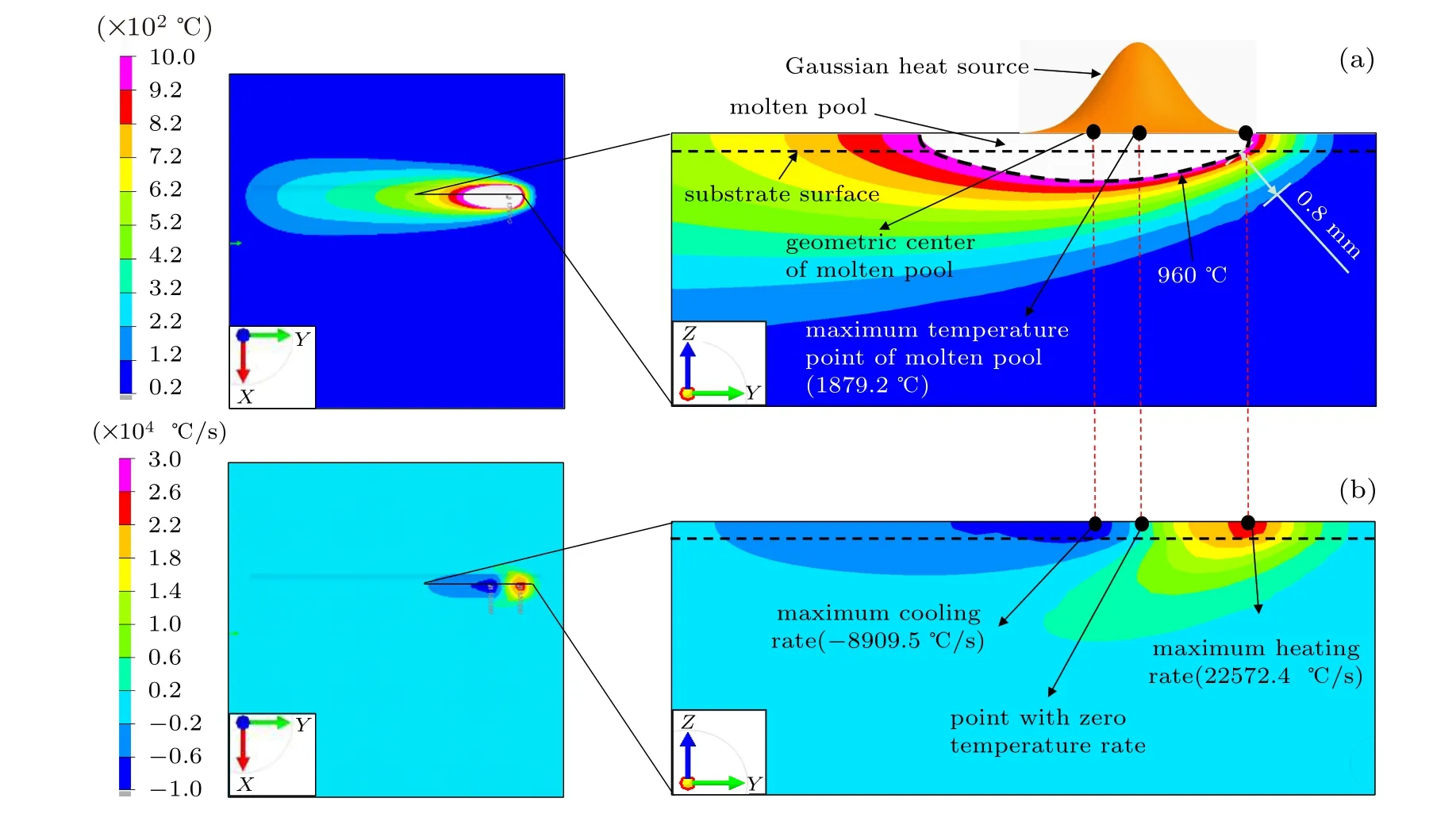
Fig.5. The cloud images of(a)temperature and(b)temperature rate for the overlap ratio of 10%at t=1 s.
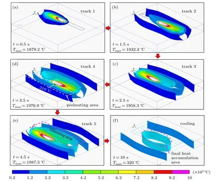
Fig.6. The temperature evolution process of the five-track laser cladding coating with an overlap rate of 10%: (a)t=0.5 s;(b)t=1.5 s;(c)t=2.5 s;(d)t=3.5 s;(e)t=4.5 s;(f)t=10 s in the cooling process.
During the cooling process after t=5 s,the highest temperature position of the coating is located at the center of the fourth track coating due to heat accumulation, which will result in the highest residual stress and increase the crack susceptibility in this position. Increasing the overlap ratio will gradually shift the highest temperature position in the cooling process to the center of the cladding coating. When the overlap ratio is 30%,the position is in the middle of the third and fourth coating. When the overlap ratio is 50%, the highest temperature position is located in the third track cladding coating.
At the same time,the scanning speed is also an important factor affecting the highest temperature position in the cooling process. The simulation results in the Refs.[15,23]show the heat accumulation always tends to the last track coating for the laser cladding with a scanning speed of 3 mm/s and an overlap ratio of 50%. While in our study, a high scanning speed of 25 mm/s is used. High scanning speed puts the middle of the substrate in poor heat dissipation condition,and then the final heat accumulate appears in the region.
Further,the temperature evolution processes of the points on the top center of each track cladding coating are monitored.The positions of the five points, P1, P2, P3, P4, and P5, are shown in Fig.7(a). The corresponding temperature evolution curves for the overlap ratios of 10%,30%,and 50%are shown in Figs.7(b),7(c),and 7(d),respectively.

Fig.7. (a)The positions of the five monitored points and their corresponding temperature evolution curves for the overlap ratio of(b)10%,(c)30%,and(d)50%.
Figure 7 shows that the laser heat source will reheat the previous track coating,and there is an apparent second temperature peak caused by the reheat effect during the laser cladding process.For example,the second peak temperature of point P1 rises again to 406.7?C during the second track cladding process,as Fig.7(b)shows. Due to the heat accumulation effect,the second peak temperatures of each monitored point increase with the proceeding of the laser cladding. And the laser heat source can preheat the substrate of the next track coating;thus,the maximum temperature of each monitored point increases with the proceeding of the laser cladding. From Fig. 7(b),we can see that the maximum temperature of the point P1 is 1879.2?C for the overlap ratio of 10%, while the maximum temperature of the point P2 rises to 1902.3?C.
Meanwhile, the maximum temperature and the second peak temperature of each monitored point also increase with the overlap ratio increasing. For example,with the overlap ratio increasing from 10% to 50%, the maximum temperature of the point P5 changes from 1957.3?C to 2028.1?C,as well as the second peak temperature of the point P1 changes from 406.7?C to 967.1?C.When the overlap ratio increases to 50%,the second peak temperature of the point P1 reaches 967.1?C,higher than the melting point of Ni60A(960?C),which means that more than half of each track cladding coating will be remelted. This“re-melting”phenomenon[42]can strengthen the metallurgical bonding between the adjacent track coating and improve the cladding coating performance.[25]
4.3. Stress and deformation evolution
Firstly,the stress and strain distribution of the coating and substrate at t =1 s is analyzed, including Von Mises stress(VMS),transverse stress,and longitudinal stress,as shown in Fig. 8. In the laser cladding process, powder materials and a part of the substrate are melted, forming a high-temperature molten pool. Because the VMS and thermal stress of the melted metal are very tiny, then it is convenient to judge roughly the solid-liquid interface of the molten pool with VMS and thermal strain clouds, as Fig. 8(a) shows. The materials adjacent to the molten pool also are heated to high temperatures and will have a large thermal expansion (Fig. 8(b)),but its expansion will be limited by the surrounding lowtemperature materials (Fig. 8(e)), thus resulting in compressive stress and large thermal strain in the area. After the laser heat source passing through, the molten pool material begins to cool down and solidify. Due to the solidification shrinkage of the cladding coating, it generates compressive stress in the transverse direction (see Fig. 8(c), and tensile stress in the longitudinal direction(Fig.8(d)). The complex stress distribution will pull the substrate upward to bend and deform(see Fig.8(e)),which damages the original appearance of mechanical parts and even causes cracks and other defects, thus affecting their corrosion and wear resistance and fatigue life.
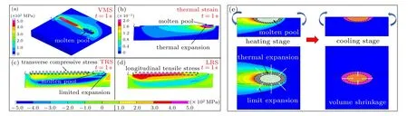
Fig.8. The cloud images of(a)Von Mises stress,(b)longitudinal section thermal strain,(c)longitudinal section transverse stress,and(d)longitudinal section longitudinal stress,as well as(e)the stress and deformation mechanism of the laser cladding process.
The transverse compressive stress is beneficial to suppress the generation of cracks. In contrast,the excessive longitudinal tensile stress will lead to the generation and propagation of cracks.[40]Especially under the cyclic load working condition, cracks will be easy to occur and propagate at the interface of the coating and substrate. Meanwhile, the stress state of the cladding coating is also closely related to the overlapping ratio, which will make the stress distribution at the joint of coating and substrate more complex. Further,the longitudinal stress evolution process at path 1 for different overlap ratios are given, where path 1 is in the middle of the interface between the coating and substrate and perpendicular to the cladding track,as Fig.9 shows.
The results show that due to the reheat effect, the deposition of each new track coating reduces the longitudinal stress of the previous track coating,which is defined as‘stress release’.[23]For example, when the overlap ratio is 10%, the stress value decreases from 377 MPa at t=3 s to 199 MPa at t =4 s during the fourth track cladding. Meanwhile, a local stress peak will form at path 1 after each track coating is deposited. And due to the preheat effect, the longitudinal stress peak value decreases with the tracks increasing. That is because the preheat effect can reduce the temperature difference between the cladding coating and the substrate of the next track. For the coating with an overlap ratio of 10%, its local stress peak value changes from 377 MPa at t =3 s to 307 MPa at t=4 s,as Fig.9(b)shows.
There are stress release and the decreased stress peak phenomena for all the three overlap ratios, which are closely related to the reheat and preheat effects. Moreover,with the increase of the overlap ratio,the lapped area between each track coating increases,and part of the high-temperature surface of the previous track cladding coating will become the substrate of the next track cladding layer. Due to the heat treatment effect between each track coating, the average residual stress for the multi-track coating is relatively lower than that of the single-track laser cladding coating.
Stress and deformation are closely related to each other.Further,the longitudinal deformation evolution for the overlap ratio of 10%is obtained,as shown in Fig.10. In order to observe the deformation process clearly,the deformation value of the cloud image is magnified by 50 times,and the middle point of one end of the upper surface of the substrate is fixed as the clamping condition of the numerical model(see Fig.10(a)).
From Figs.9 and 10, we can see that after the first track cladding coating is finished (t =1 s), the substrate presents a slight upward “convex” trend, as shown in Fig. 9(b). In addition, there is large tensile stress inside the coating due to its solidification shrinkage, and compressive stress inside the substrate surrounding the coating due to its thermal expansion limited by the surrounding low-temperature material, as shown in Fig.10(b). At t=2 s,there is an apparent stress relaxation phenomenon of the first track coating due to the reheat effect. During the subsequent cladding process,the stress distribution and stress relaxation phenomena of each track coating are similar to that of the first track coating. However, the tensile stress area increases,and the compressive stress amplitude and area of the surrounding substrate also gradually increase.Meanwhile,the substrate”concave”deformation gradually becomes more serious.
When the fifth track coatings are finished at t =5 s, the substrate shows an apparent“concave”deformation,as shown in Fig.10(f). Finally,when the substrate is fully cooled down at t=3600 s,it shows longitudinal tensile stresses in the coating area,and the surrounding substrate exists large longitudinal compressive stresses, as shown in Fig. 9(b). The reason is that the tensile stress, caused by the solidification shrinkage of the cladding coatings and the nearby high-temperature materials,leads to the upward bending of the substrate,which will compress the surrounding substrate,thus resulting in compressive stress in the region. At the same time,the transverse shrinkage of the cladding coating will also cause the substrate to bend upward, then finally the substrate is in the“concave”state.

Fig.9.The location diagram of(a)path 1 at the interface between coating and substrate,and the corresponding longitudinal stress evolution on path 1 for the overlap ratios of(b)10%,(c)30%,and(d)50%.

Fig.10. For the coating with an overlap ratio of 50%,its stress and deformation evolution varying with time: (a)t=0.1 s,(b)t=1 s,(c)t=2 s,(d)t=3 s,(e)t=4 s,and(f)t=5 s.
The stress evolution mechanism and the substrate deformation trend for the three overlap ratios are consistent.However, the final longitudinal stress distribution and amplitude of the cladding coating vary with the overlap ratio. At t =3600 s, the maximum longitudinal residual stress (LRS)tends to locate at the middle of the substrate with the overlap ratio increasing. For example, the maximum LRS appears near the fourth cladding coating for the overlap ratio of 10%,while the maximum LRS appears near the third cladding layer for the overlap ratios of 30% and 50%, as Figs. 9(c)and 9(d) show. It is closely related to the heat accumulation during the laser cladding. The heat accumulation region will be the last one to finish the solidification shrinkage process, which leads to the largest residual tensile stress in the region.
It is worth noting that there is an apparent residual stress mutation at the overlap joint of each track coating for the overlap ratio of 10% (Fig. 9(b)), which may cause geometric defects. In order to analyze the reason, the temperature, stress,and strain evolution of node 3(N3)and middle node(MN)on path 1 are extracted,as Fig.11 shows.
The difference in stress and strain curves of points N3 and MN is mainly related to their temperature evolution. During the laser cladding process, the highest historical temperature of point N3 is 1185.9?C (larger than the melting point of 1180?C), and it will melt when the temperature exceeds the melting point. While the historical maximum temperature of point MN is 1089.9?C, which means it is in a solid phase throughout(see Fig.12(c)). When the laser heat source passes through the two points, the material at point N3 will melt, its stress reduces to zero instantly, and then the tensile stress will be produced during the subsequent cooling process. However, for the point MN, the compressive stress will be generated due to the restriction of surrounding materials on its high-temperature thermal expansion, and the compressive stress reaches the maximum value when the heat source passes through. Their different stress evolution behaviors finally result in the different residual stress of the two points.
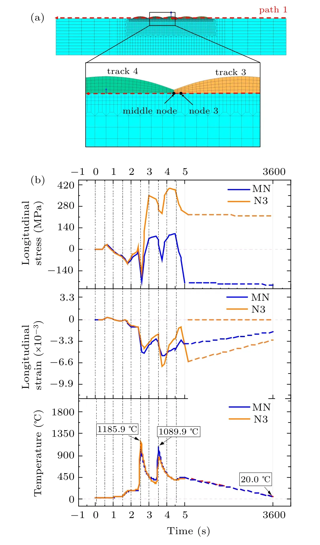
Fig. 11. The position of (a) the monitoring points N3 and MN, and their corresponding(b)temperature,stress,and strain evolution curves.
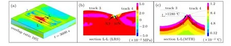
Fig.12. (a)The location diagram,(b)longitudinal residual stress cloud image,and(c)maximum temperature history cloud image of the L-L section for the coating with an overlap ratio of 10%.
Further, the residual longitudinal stress and maximum temperature history cloud images of the L-L cross-section including N3 and MN points are obtained,as shown in Fig.12.The results show that due to the low overlap ratio,the input energy at the lap joint is insufficient, which makes the lap joint in a compressive stress state,while the rest region of this section is in a tensile stress state. The sudden stress change will lead to geometric defects at the lap joint.[13,43,44]Therefore,the overlap ratio of multi-track cladding coating should not be too low,otherwise unnecessary defects and abnormal residual stress may appear at the lap joint(see Fig.12(b)),resulting in cracks and reducing the fatigue life of the cladding coating.
4.4. Residual stress and deformation
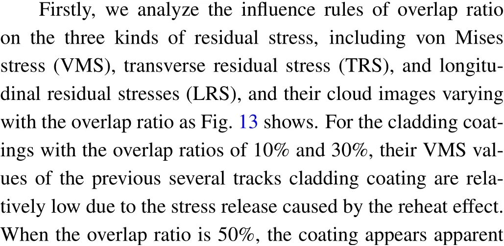
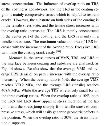

Fig.13. The residual stress distributions of VMS,TRS,and LRS for the overlap ratios of 10%,30%,and 50%.
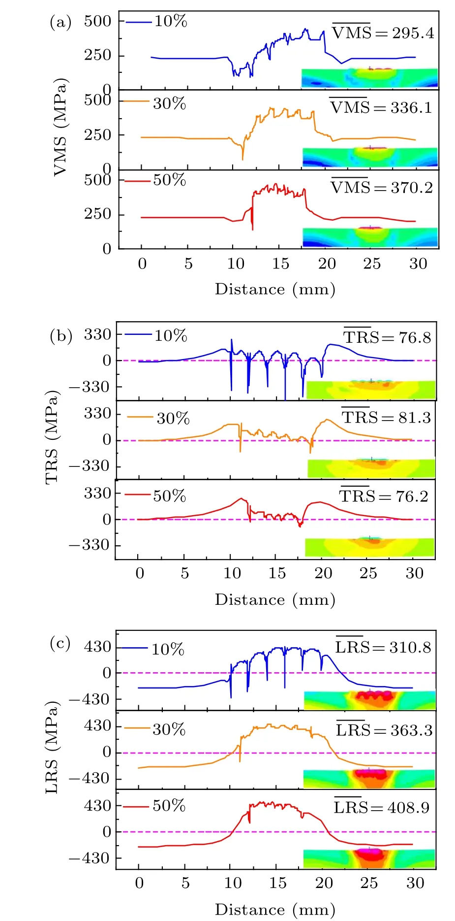
Fig. 14. The (a) VMS (b) TRS and (c) LRS on path 1 for coating with overlap ratios of 10%,30%,and 50%.
After the complex temperature, stress, and strain evolution process, the substrate and cladding coating will produce not only residual stresses but also large residual deformations. In order to analyze the residual deformation of the cladding substrate,the deformation of the fixed point(given in Fig. 10(a)) is set to zero. The residual deformation cloud of the cladding substrate with the overlap ratio of 10%is shown in Fig.15(a),and its maximum deformation is about 0.46 mm.At the same time,the residual deformations at the four corners of the cladding substrate for the three different overlap ratios are obtained, as shown in Fig. 15(b). Results show that with the increase of the overlap ratio, the deformations of the four corners decrease, and the deformation trends for all the three overlap ratios are consistent,that is,concave in the center and warping in four corners of the substrate.

Fig.15. (a)Residual deformation cloud image of the coating with an overlap ratio of 10%and(b)effect of overlap ratios on the residual deformation at the four corners of the cladding substrate.

Fig.16. The cloud images of(a)maximum temperature history and(b)longitudinal residual stress of the crosssection including path 1 for the coatings of 10%,30%,and 50%.
High overlap ratio enhances the heat accumulation depth,and makes the tensile residual stress extend to the deeper position of the substrate,as shown in Fig.16,which will balance part of the LRS of the upper surface caused by the coating shrinkage,and decrease the upward warping trend of the substrate,but increase the final VMS and LRS.Therefore,according to the thickness of the substrate and the allowable deformation,the overlap ratio can be increased appropriately to improve the cladding coating quality and to reduce residual deformation and the possibility of cracks. However,a high overlap ratio will increase the heat amount per unit volume, thus enlarging the heat-affected zone and hardening depth of the substrate,and increasing the average residual stress.
5. Conclusion
In the paper, the geometric model of high-speed laser cladding coating is established based on the corresponding laser cladding experiment. And a thermal-stress sequential coupling numerical model is developed to reveal the evolution mechanism of temperature, stress, and strain during the laser cladding process and study the influence of the overlap ratio on their evolution rules.
The temperature,strain,and stress evolution processes of the multi-track cladding coating are extremely complex. During the laser cladding process,with the increase of the overlap ratio,the heat accumulation tends to the center of the cladding coating, which is related to the scanning speed and heat dissipation conditions. Thus, the highest LRS also inclines to locate at the center of the laser cladding coating. When the overlap ratio is 10%, the largest LRS appears near the fourth track cladding coating.For the overlap ratios of 30%and 50%,the maximum residual LRS appears near the third cladding coating.
For the coating with a small overlap ratio,there are apparent residual stress mutations at the lap joint, which will tend to form cracks. High overlap ratios will slow down stress relaxation, enhance the preheating treatment strength, and reduce the residual deformation. When the overlap ratio is 50%,more than half of each track coating will be re-melted,which will enhance the metallurgical bond strength and reduce the geometric defects. However,increasing the overlap ratio will enlarge the heat-affected zone and hardening depth of the substrate,and also will increase the average residual stress.
猜你喜歡
思維與智慧·上半月(2025年2期)2025-02-21 00:00:00
民間故事選刊(2022年20期)2022-10-30 01:10:29
民間故事選刊·下(2022年10期)2022-05-30 15:51:26
民族音樂(2019年6期)2020-01-15 06:50:20
創(chuàng)新作文(小學版)(2019年10期)2019-09-25 08:12:22
小學生導刊(2018年1期)2018-03-15 08:02:41
草原歌聲(2018年3期)2018-01-24 07:06:52
小天使·四年級語數(shù)英綜合(2017年6期)2017-06-07 22:45:22
第二課堂(初中版)(2017年3期)2017-05-08 09:58:58
民間故事選刊·下(2014年2期)2014-02-26 02:21:22
- Chinese Physics B的其它文章
- Numerical simulation on ionic wind in circular channels*
- Interaction properties of solitons for a couple of nonlinear evolution equations
- Enhancement of multiatom non-classical correlations and quantum state transfer in atom–cavity–fiber system*
- Protein–protein docking with interface residue restraints*
- Effect of interaction between loop bases and ions on stability of G-quadruplex DNA*
- Retrieval of multiple scattering contrast from x-ray analyzer-based imaging*