
Effects of splined shaft bending rigidity on cylinder tilt behaviour for high-speed electrohydrostatic actuator pumps
2019-02-27 09:00:12JunhuiZHANGYunCHENBingXUMinPANQunCHAO
CHINESE JOURNAL OF AERONAUTICS 2019年2期
Junhui ZHANG,Yun CHEN,Bing XU,Min PAN,Qun CHAO
aThe State Key Laboratory of Fluid Power and Mechatronic Systems,Zhejiang University,Hangzhou 310027,China
bDepartment of Mechanical Engineering,University of Bath,Bath BA2 7AY,United Kingdom
Abstract High-speed axial piston pumps are hydraulic power supplies for electro-hydrostatic actuators(EHAs).The efficiency of a pump directly affects the operating performance of an EHA,and an understanding of the physical phenomena occurring in the cylinder/valve plate interface is essential to investigate energy dissipation.The effects of the splined shaft bending rigidity on the cylinder tilt behaviour in an EHA pump need to be considered,because the deflection and radial expansion of a steel shaft rotating at a high speed cannot be ignored.This paper proposes a new mathematical model to predict the cylinder tilt behaviour by establishing a quantitative relationship between the splined shaft deflection,the cylinder tilt angle,and the tilt azimuth angle.The moments exerted by the splined shaft are included in the equilibrium equation of the cylinder.The effects of solid and hollow splined shafts equipped in an EHA pump prototype are compared at variable speeds of 5000-10,000 r/min.With a weight saving of 29.7%,the hollow shaft is experimentally found to have almost no influence on the volumetric efficiency,but to reduce the mechanical efficiency by 0.6-2.4%.The results agree with the trivial differences of the simulated central gap heights of the interface between the two shafts and the enlargement of the simulated tilt angles by the hollow shaft.The findings could guide designs of the cylinder/valve plate interface and the splined shaft to improve both the efficiency and power density of an EHA pump.
KEYWORDS Electro-hydrostatic actuator pump;Mathematical models;Rigidity;Splined shaft deflection;Tilt behaviour prediction
1.Introduction
High-speed axial piston pumps are commonly applied in aircraft and carrier rockets due to their high power density as well as weight and space savings.Lightweight and compact pumps in small packages with stable operation and high power efficiency over the full operating range are consistently pursued.1,2This challenge requires employing low-density materials and downsizing pump components without compromising their strengths.Replacing the solid shaft with a hollow one is among the methods,since the strength-to-weight ratio of a hollow shaft could be 36%greater than that of a solid shaft with the same outer radius.3However,the shaft bending rigidity is reduced by removing the core of the shaft.According to the structure of a typical axial piston pump used in an electro-hydrostatic actuator(EHA)for aerospace applications,a splined shaft drives and supports the cylinder.The cylinder tilt behaviour will be influenced if the curvature of the splined shaft is large enough.Previous studies have shown that the deflection and radial expansion of a steel shaft due to the bending load and the temperature rise caused by a high operating speed cannot be ignored.4,5Since the cylinder/valve plate interface represents one of the main sources of energy dissipation,6the excessive bending of the splined shaft would reduce the pump efficiency by raising the contact friction and leakage flow.
The lubrication characteristics of the cylinder/valve plate interface need to be investigated in order to understand the relationship between the splined shaft bending rigidity and the cylinder tilt behaviour.Although some practical and convenient design methods based on the assumption of a constant gap height between the cylinder and the valve plate are popular in the industry,7,8the dynamic characteristics of a cylinder rotating at a high speed are complicated due to various forces acting on it,including the inertia forces of the piston-slipper assemblies.9The micro motion such as the tilt behaviour directly affects the lubricating film geometry and even causes severe wear,which will contribute to a sharp decrease of the pump efficiency or damage the rotating kit.
Different mathematical models considering the cylinder tilt behaviour were proposed to reveal the characteristics of the oil film in order to estimate the energy losses of the friction pair.Bergada et al.10developed a detailed set of explicit equations to determine pressure distribution,leakage,forces,and moments for the cylinder.Their calculation was based on the assumption that the thickest oil film was on the highpressure side.Zecchi and Ivantysynova11developed a fluid structure thermal interaction model accounting for nonisothermal flow in the gap between the cylinder and the valve plate,as well as pressure and thermal elastic deformations in the solid bodies.Wegner et al.12implemented a simulation model and a solid friction model for the cylinder/valve plate interface to compare different design geometries at various operating points.In these models,the reaction moments of the splined shaft were not considered or assumed to be zero.Yamaguchi13theoretically analysed the motion of the cylinder considering the influence of the elastic splined shaft and predicted the fluid film shape for different load conditions.However,the inertia forces of the piston-slipper assemblies,especially the relation between the splined shaft deflection and the cylinder tilt behaviour,were not taken into account.
Experimental studies were also undertaken to investigate the influences of operating conditions and relevant dimensions of pumps on the cylinder tilt behaviour.Bergada et al.14measured the clearance between the cylinder and the valve plate.They found that the maximum film thickness position moved to a new location at a low temperature,a small swash plate angle,and a low outlet pressure.Deeken15measured the gap height of the cylinder/valve plate pair on a special test rig.His measured and simulated results showed a good corresponding tendency that the cylinder tilt angle decreased as the outlet pressure increased.It was also found that the variation of the rotational speed gave rise to a change in the tilt azimuth.Kim et al.16measured the fluid film thickness with different structures of the valve plate sliding surfaces.They found that the outlet pressure and the structures significantly affected the thickness and location of the minimum fluid film.The above experiments were conducted at a low speed of less than 2000 r/min,and the effects of the splined shaft bending rigidity were not studied.It can be concluded that the previous findings did not provide enough information for guiding the design of high-speed EHA pumps.
Splined shafts are commonly used in pumps to transfer rotary motion and torsion to cylinders.The cylinder tilt behaviour can lead to an angular misalignment between the cylinder and the splined shaft which has been recognized as a harmful behaviour to splines because it accelerates fretting and abrasive wear.17Hong et al.18studied the load distributions on the spline at different misalignment angles of 0.04°,0.08°,and 0.12°,demonstrating that a significant load concentration was generated at the edge of the spline and thus resulted in an unnegligible tilt moment which could even deflect the splined shaft.Therefore,the moment equilibrium equation of the cylinder needs to include the tilt moment caused by the splined shaft.
This paper aims to study the effects caused by the splined shaft bending rigidity on the micro motion of the cylinder and EHA pump performances.A predicting model considering the splined shaft deflection is established to achieve the cylinder tilt angle,tilt azimuth angle,and the central gap height during an entire shaft revolution under various operating conditions.Performance tests of an EHA pump prototype are carried out on a high-speed test rig to verify the predicting model.The effects of solid and hollow splined shafts are compared to guide the design of high-speed EHA pumps.
2.Mathematical model
A double-direction EHA pump,which integrates a nine-piston rotating group and can operate at a high speed of up to 10,000 r/min,is used for investigation.The hydraulic circuit of its regulator system and the ideal pressure-displacement characteristic curve are presented in Fig.1.The maximum displacement is 7.25 mL/r.When the pressure at the outlet exceeds the value of the turning point determined by the precompressed length of the spring pressing the swash plate,the displacement decreases linearly as the pressure increases.
The main inner parts of the EHA pump are shown in Fig.2.In Fig.2(a),a cross-sectional view of the EHA pump with external forces and coordinate systems is depicted.The valve plate is fixed on the shell of the pump with two pins,and a compression spring generating a spring force,Fsp,pushes the cylinder towards it.The cylinder is driven via the splined shaft which is supported by a sleeve bearing and a deep groove ball bearing.The piston-slipper assemblies revolve with the cylinder,and a centrifugal force,Fci,acts at each assembly's centre of mass.Meanwhile,each piston moves back and forth inside the cylinder chamber,periodically suctioning and discharging oil through the valve plate ports.The pressurized fluid inside each cylinder chamber exerts the primary force,Fpi,in theZaxis.The swash plate creates a side force,Fsi,acting on the centre of each piston-slipper ball joint due to its inclination.The friction force produced between the piston and the cylinder bore is not considered.TheZaxis is coincident with the centreline of the splined shaft.The origin of the coordinate systemO-XYis at the supporting point of the deep groove ball bearing.The coordinate systemO1-X1Y1is assigned to the cylinder/valve plate interface.The coordinate systemO2-X2Y2is attached to the intersection point of theZaxis and the plane containing the centre points of each piston-slipper ball joint,which is also in the centre of the spline length.
The cylinder with sector pads uniformly distributed in a circle outside the external sealing land is illustrated in Fig.2(b).Sealing land and sector pad dimensions as well as the rotation angle θ1are presented,too.The valve plate with main kidney port and timing groove dimensions can be found in Fig.2(c).Because the research object is a double-direction pump,the grooves connecting the ports are axis-symmetrically distributed.Therefore,the sealing lands as well as the main kidney ports and the timing grooves are divided into 18 subregions to evaluate the pressure distribution,respectively,which are numbered from 1 to 18.When the cylinder rotates clockwise as shown in Fig.2(b),the high-and low-pressure ports are distributed as shown in Fig.2(c).
2.1.Effect of the deflected splined shaft
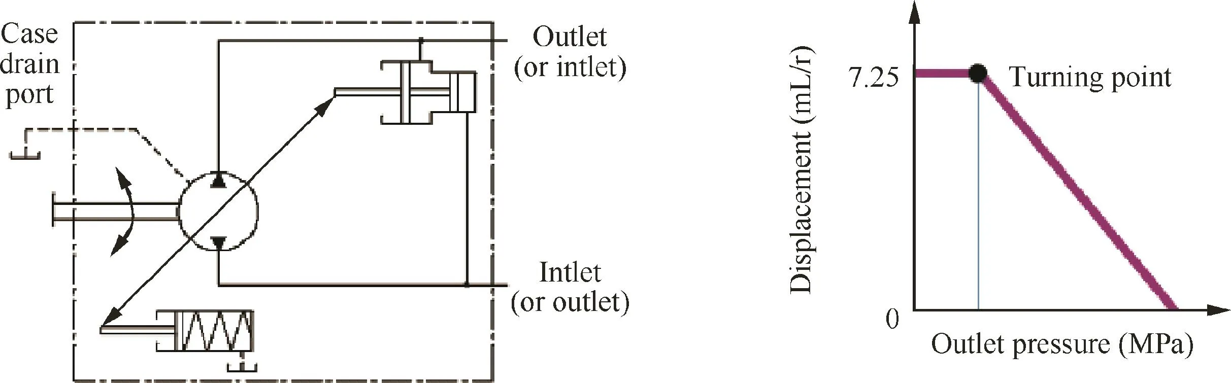
Fig.1 Hydraulic circuit of the EHA pump's regulator system(left)and ideal pressure-displacement characteristic curve(right).
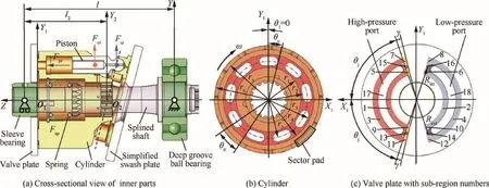
Fig.2 Main inner parts of the EHA pump.
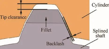
Fig.3 Fillet,tip clearance,and backlash of the spline pair.
The fillet,tip clearance,and backlash of the spline pair shown in Fig.3 allow the cylinder to slightly tilt in absence of constraints before interfering with the splined shaft.However,the flash temperature of the spline tooth surfaces can reach about 180°C even at a rotational velocity of 2090 r/min,19which means that the thermal expansion would diminish the clearance between spline teeth.Additionally,when the pump operates,almost all the teeth of the external spline are in contact with the internal spline,and significant load concentrations are caused at the ends of the spline in theZaxis.18Therefore,to derive equations considering the influence of the deflected splined shaft,the following simplifications and assumptions are made in this study:
I.When the compact EHA pump operates at a high ambient temperature caused by the high operating speed,the clearance between spline teeth is assumed to be diminished so that no matter how small the cylinder tilt angle is,the splined shaft will be deflected at the same angle.
II.The load concentrations on the cylinder spline are simplified as two concentrated forces,and their acting points are assumed to locate at either edge of the spline as depicted in Fig.4,where the cylinder tilt angle and the splined shaft deflection are exaggerated.
III.The splined shaft is assumed to be a simply supported beam,aiming to establish practical equations of the relation between the parameters determining the cylinder tilt behaviour and the splined shaft deflection.
The maximum cylinder tilt angle α and the clearance heighthhave the following relation in a full fluid film lubrication regime10:

As shown in Fig.5,the maximum tilt angle α occurs at the tilt azimuth angle θαwhere the oil film is thickest.At the same location,the local azimuth angle θ is 0°.h0is the central gap height.
According to Assumptions I-III,the cylinder is subjected to tilt moments about theX2andY2axes,Mx_shaftandMy_shaft,and the splined shaft bends in the same azimuth as the cylinder tilt,as illustrated in Fig.4.Thus,the directions of the moments acting on the splined shaft are opposite toMx_shaftand
My_shaft.The angle between the tangent to the deflected shaft at pointO2and theZaxis would be equal to the cylinder tilt angle.The aforementioned relations between the parameters determining the cylinder tilt behaviour and the splined shaft deflections are defined as follows:
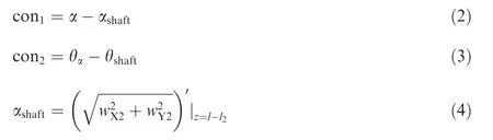
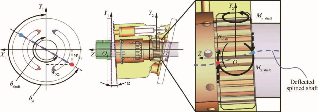
Fig.4 Tilt moments caused by two concentrated forces on the cylinder spline.
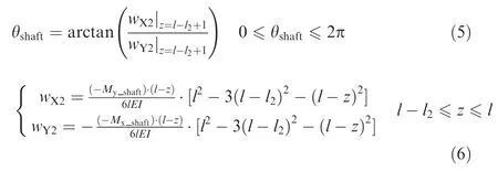
where con1and con2are the balance parameters with the unit of radian;αshaftis the angle between the tangent to the deflected shaft at pointO2(z=l-l2)and theZaxis;θshaftis the angle between the bending direction of the splined shaft and theY1axis at pointz=l-l2+1;wX2andwY2are the deflections of the splined shaft along theX2andY2axes,respectively,which are derived by integrating the differential equation of the deflection curve for a simply supported beam.3Because the values ofwX2andwY2at pointO2are zero,θshaftis calculated at the point which is 1 mm away from pointO2,that is,z=l-l2+1.
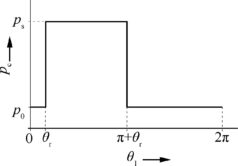
Fig.6 Simplified pressure profile for the first cylinder chamber where θr= π/2- θj- θc- γ.
2.2.Forces and moments on cylinder
The pressure distribution for the first cylinder chamber in Fig.2(b)is shown in Fig.6,neglecting the trapping phenomenon and the influence of back flow.From the moment that the cylinder port starts to connect the high-pressure port of the valve plate(θ1= θr)to the moment that it starts to connect the low-pressure port(θ1= π + θr),the cylinder chamber pressure,pc,is equal to the outlet pressureps;otherwise,pcis equal to the inlet pressurep0.Thus,Fpiis described as in Eq.(7).Due to the nonuniform pressure distribution for the cylinder chambers,Fpialso creates moments about theX2andY2axes,Mx_pandMy_p,as in Eqs.(8)and(9).Every 2π/9 rad of rotation,the pressure distribution for the cylinder chambers varies with the rotation angle θ1as
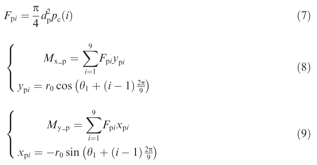
whereypiandxpiare the moment arms to theX2andY2axes,respectively.
FciandFsiare shown in Eqs.(10)and(11).They create two moments about theX2axis as in Eqs.(12)and(13).
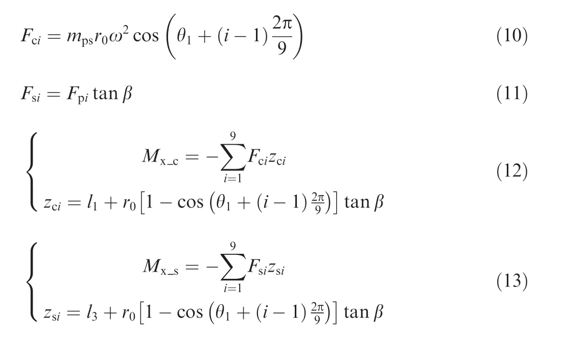
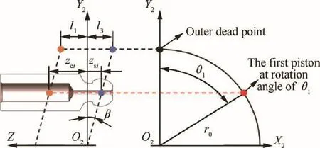
Fig.7 Schematic of piston motion on swash plate.
wherezciandzsiare the moment arms to theX2axis,which are calculated according to the piston motion on the swash plate shown in Fig.7.
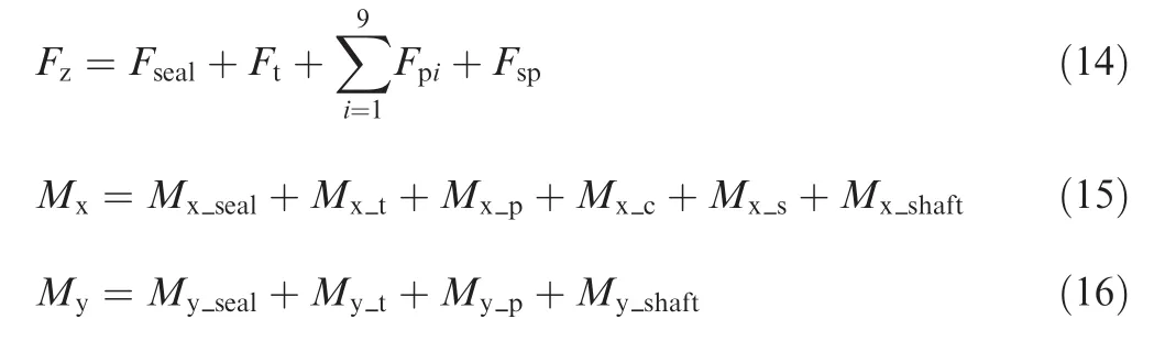
FciandFsiare transferred to the cylinder through the piston/-cylinder lubricating gap.All the forces and moments mentioned above are balanced by the fluid film in the cylinder/valve plate interface.The hydrostatic and hydrodynamic effects play a dominant role in determining the pressure distribution for the sealing lands.For the sector pads outside the external sealing land,the hydrostatic pressure approaches the tank pressure.However,the shear velocity of the sector pads is high enough to generate extra pressure caused by the thermal wedge effect which is much higher than the tank pressure.As a result,the force,Fseal,and moments,Mx_sealandMy_seal,due to the pressure distribution for the sealing lands as well as the main kidney ports and the timing grooves,and the force,Ft,and moments,Mx_tandMy_t,due to the pressure distribution for the sector pads compose the forces and moments generated by the fluid film in the cylinder/valve plate interface.
The cylinder is balanced when the resultant external force in theZaxis,Fz,and moments about theX2andY2axes,MxandMy,are equal to zero,as written in the following equations:
2.2.1.Effects of main kidney ports and the timing grooves
piseal(r,θ)is the pressure distribution for the sealing lands as well as the main kidney ports and the timing grooves,and the subscript denotes an identifier of the sub-regions as shown in Fig.2(c),that is,p1represents the pressure distribution for the internal sealing land along the main kidney port on the high-pressure side.Supposing that the gap flow between the cylinder and the valve plate is laminar and incompressible and moves only in the radial direction,the Reynolds equation in the polar coordinate is
where iseal=1,2,...,11,12.When iseal=13,15,17,piseal=ps;when iseal=14,16,18,piseal=p0.
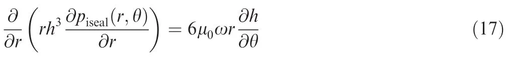
After the first integration,Eq.(17)turns into Eq.(18),and after the second integration,Eq.(19)is obtained.The constantsC1andC2are related to the boundary conditions along the main kidney ports and the timing grooves in Eq.(20).
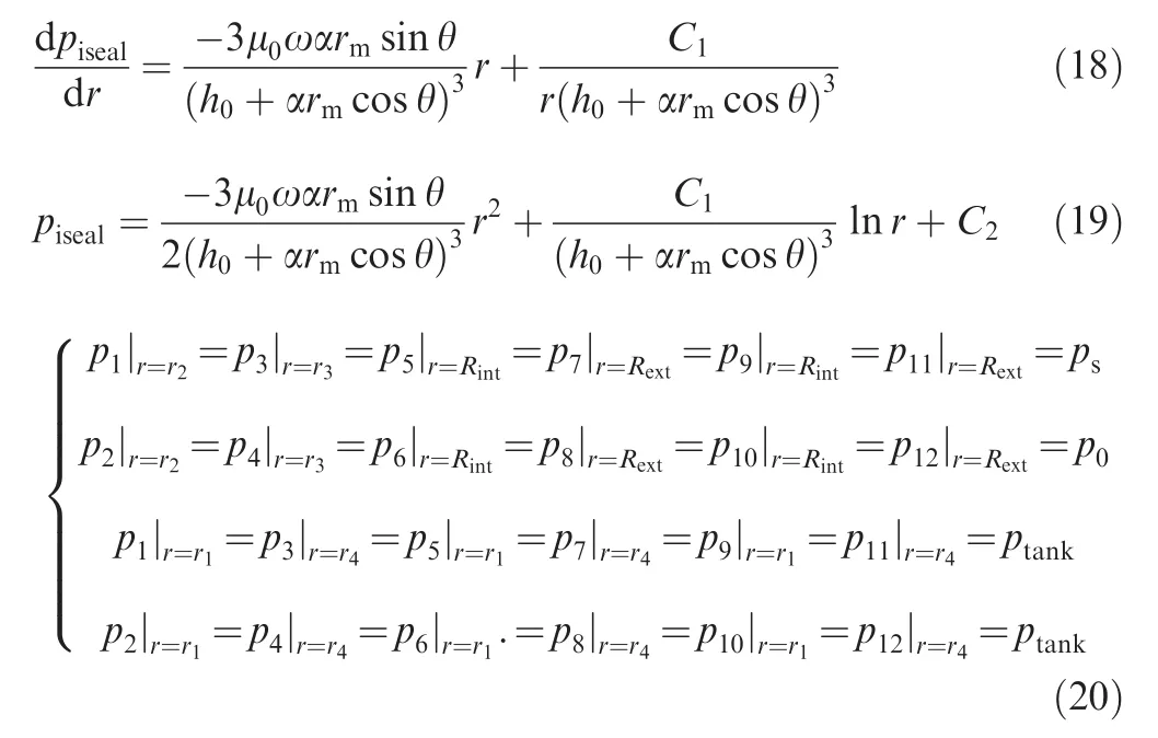
The pressure distributionpiseal(iseal=1,2,...,11,12)is given in Eq.(21),and the values of the constantsrn,re,rm,andpxare given in Table 1 for different values of iseal.
Because the tilt cylinder generates a converging oil film region and a diverging oil film region at the same time,large negative pressures would appear in the diverging region if the Sommerfeld boundary condition is used.20Therefore,the half-Sommerfeld boundary condition is employed,and the negative pressure values ofpiseal(r,θ)are set to bepiseal(r,0).21
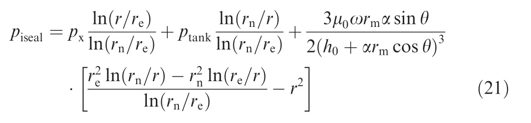
The forces and moments due to the pressure distributionpisealare expressed as in Eqs.(22)-(24).The effect of the tilt azimuth angle θαis considered,while the influence caused by the cylinder rotation angle θ1is ignored.Fiseal,Mx_iseal,andMy_isealrepresent the force and moments created by the corresponding pressure distributionpiseal.The values of the constants θd,θs,rd,andrsare listed in Table 2 for different subregions.
Thus,the force,Fseal,and moments,Mx_sealandMy_seal,due to the pressure distribution for the sealing lands as well as the main kidney ports and the timing grooves are obtained as follows:
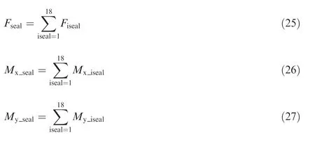
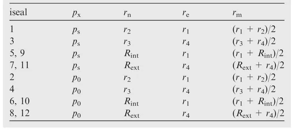
Table 1 Values of the constants rn,re,rm,and pxfor different values of iseal.
2.2.2.Thermal wedge effect of sector pads
The average gap height of every sector pad in a full fluid film lubrication regime is described as follows:

whereit=1,2,...,Zt,in whichZtis the number of sector pads;rmt=(r6+r5)/2.
The starting and end azimuth angles of every sector pad can be obtained by

where θx∈ [0,θtt].
The heat generated by the Couette flow is assumed to be devoted to the temperature rise of the gap flow.22Using the average shear velocity in Eq.(30)and the energy conservation theory,the relationship between the thermal wedge bearing pressure and the fluid density variation caused by the temperature rise is established in Eq.(31).
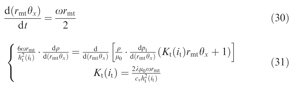
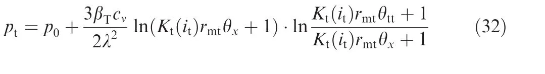
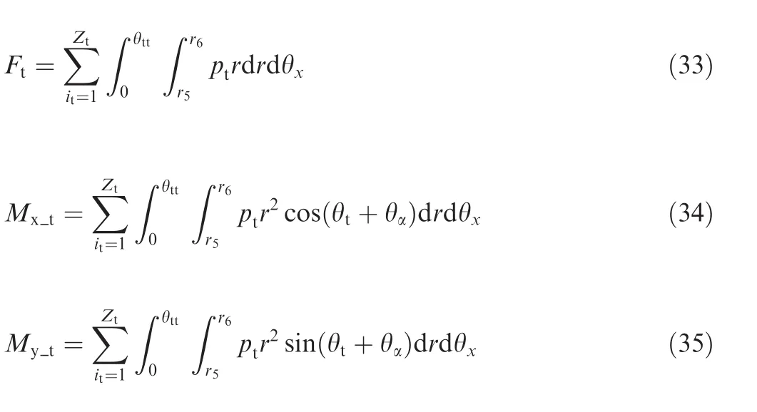
whereKt(it)is a constant for a given sector pad.Then,by integrating Eq.(31),ptis derived as The force and moments due to the pressure distribution for the sector pads are expressed as in Eqs.(33)-(35).They are influenced by both the tilt azimuth angle θαand the cylinder rotation angle θ1.Because Eqs.(34)and(35)couldn't obtain explicit integral formulas,the double integrals are numerically evaluated.
2.3.Gap flow between cylinder and valve plate
According to Poiseulle's law,the velocity distribution is as follows:

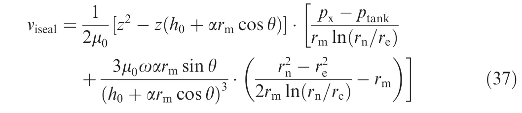
Substituting Eq.(18)and the boundary conditions into Eq.(36),the velocity distribution along the average radius is obtained in Eq.(37).The values ofrn,re,rm,andpxare given in Table 1 for different sub-regions.
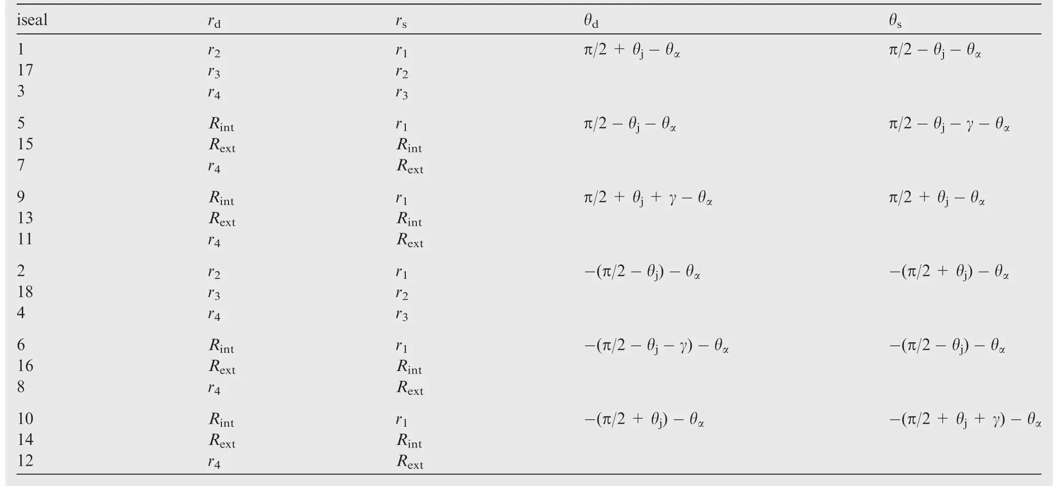
Table 2 Values of constants θd,θs,rd,and rsfor different values of iseal.
For the external sealing lands,the pressure decreases as the radius increases,which leads to the gap flow travelling outward.Therefore,the velocity for the internal sealing lands has an opposite sign compared to that for the external sealing lands.The leakage across each sub-region is shown in Eq.(38).The values of θdand θsare given in Table 2 for different subregions.
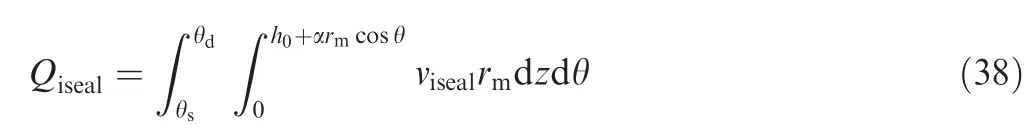
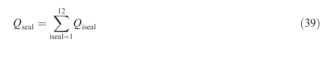
The total leakage for the valve plate is the addition of the leakage across each sub-region of the sealing lands where iseal=1,2,...,11,12 as shown below:
2.4.Iteration method
The equations described above compose a simulation model which predicts the cylinder tilt behaviour during an entire shaft revolution under different operating conditions.A schematic of the solving procedure is illustrated in Fig.8.The parameters determining the cylinder tilt behaviour are unknown in advance,so the model starts with the initial values ofh0,α,and θα,and then generates a sequence of iterates converging to a solution by using the SQP(sequential quadratic programming)method.23Since the cylinder/valve plate friction pair is assumed to operate under full fluid film lubrication conditions,the values ofh0and α are checked to avoid solid contact at each iteration step before being substituted into the nonlinear constraint functions.There are two situations for the constraint functions:(1)α=0,and(2)α>0.In the first situation,the cylinder is parallel to the valve plate,so the splined shaft provides a supporting force in theY2axis rather than moments,that is,the constraints ofMx_shaft=0 andMy_shaft=0 need to be satisfied.In the second situation,the cylinder tilts,so the balance parameters,con1andcon2,determining whether the cylinder is moment-balanced are evaluated.The net moments,MxandMy,or the balance parameters,con1andcon2,as well as the net force,Fz,are updated until a solution satisfying the constraints is found.SinceMx,My,con1,con2,andFzcannot reach the ideal value of zero due to computational errors,the simulation eventually terminates when the required accuracies shown in Fig.8 are achieved.The final values of the forces and moments described in Section 2.2 are those calculated at the last iteration step,and the gap flow of the cylinder/valve plate interface can be obtained with the solution ofh0,α,and θα.
3.Experimental procedure
Experiments of an EHA pump prototype shown in Fig.9 are conducted to validate the mathematical model.The micro motion of the cylinder and the gap flow of the cylinder/valve plate interface in a high-speed and compact pump are hard to be measured directly.Previous works proved that the cylinder tilt behaviour significantly influences the power losses of a pump.6,24Therefore,the total leakage,the input torque,and the efficiencies of the prototype are measured to investigate the effects of the splined shaft bending rigidity on the cylinder tilt behaviour.
Photographs of the high-speed test rig for measuring the pump's performance parameters are shown in Fig.9.The prototype is driven by a servo motor which can be continuously adjusted from 0 r/min to 16000 r/min.A speed torque sensor is connected to the output shaft of the servo motor.Pressure and temperature sensors are mounted on a manifold which is connected to the outlet,inlet,and case drain ports of the prototype.The total leakage of the prototype is measured by a flowmeter.The working fluid is pumped to the prototype inlet by a charge pump.Two proportional relief valves are located on the delivery lines of the charge pump and the prototype,respectively.A heat exchanger is utilized to maintain the oil temperature of the tank.Table 3 gives detailed descriptions of the main sensors used in the experiments,and signals obtained from the sensors are collected using NI DAQ modules.
The solid and hollow splined shafts assembled in the EHA pump prototype are shown in Fig.10,and the inner and outer diameters noted are used to calculate their shaft bending rigidities.On the premise that both the solid and hollow splined shafts satisfy the strength requirement,a weight loss of 0.035 kg is achieved.Compared with the weight of the solid shaft(0.118 kg),about 29.7%weight is reduced for the hollow one.The dimensions of the sealing lands and sector pads are reported in Table 4.The contacting surfaces of the cylinder and the valve plate in the tests were manufactured with a grinding process which gave a surface roughness of 0.2 μm and a flatness of 2 μm,while the mathematical model only considers an ideally smooth surface in full film lubrication.
Both the solid and hollow splined shafts are studied with a broad range of tests,performed starting from 5000 r/min and increasing in steps of 1000 r/min up to the highest speed of 10000 r/min,at an outlet pressure of 7 MPa.The outlet pressure and the speed are kept constant in each test.The value of the turning point as shown in Fig.1 is adjusted to 7 MPa in order to keep the displacement at the maximum value during the experiments.The pump operates at 1000 r/min,2 MPa for 30 min before data acquisition.
4.Results and discussion
4.1.Simulated moments on balanced cylinder
The simulated moments acting on the balanced cylinder as a function of the speed at the cylinder rotation angle θ1=0°are given in Figs.11 and 12.The magnitudes and directions of the moments are affected by the operating conditions and have a strong relationship with the cylinder tilt behaviour as analysed below.
(1)Mx_sealandMy_seal:Because the structure of the valve plate is symmetric about theX1axis,the magnitude ofMx_sealwill be zero if the cylinder is parallel to the valve plate.Accordingly,the nonzero values ofMx_sealresult from the nonuniform distribution of the oil film thickness,which leads to a hydrodynamic effect in the converging oil film region and a pressure drop in the diverging oil film region.Consequently,the moment direction ofMx_sealindicates whether the cylinder tilts towards the positive or negativeX2axis,and it can be judged that the location of the minimum gap height lies on the positiveX2axis at all the tested speeds from 5000 to 10000 r/min.The magnitude ofMy_sealgradually declines as the speed rises,stemming from a decreased tilt angle or an increased central gap height while the cylinder tilts towards the negativeY2axis,or from the reason that the location of the minimum gap height moves towards the positiveY2axis.
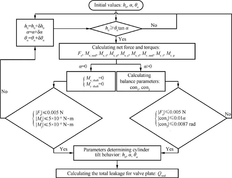
Fig.8 Simulation scheme.
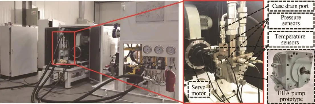
Fig.9 EHA pump prototype and the high-speed test rig.
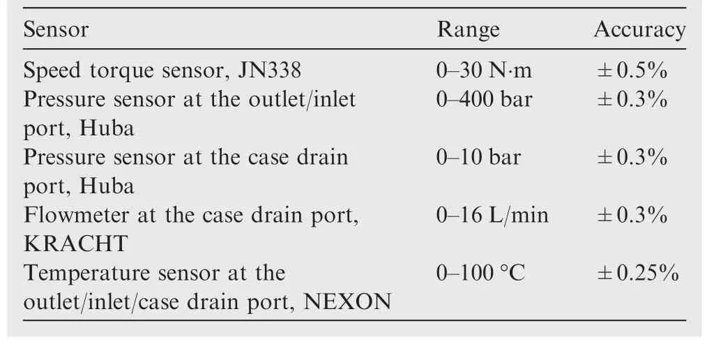
Table 3 Detailed descriptions of main sensors used in the experiments.
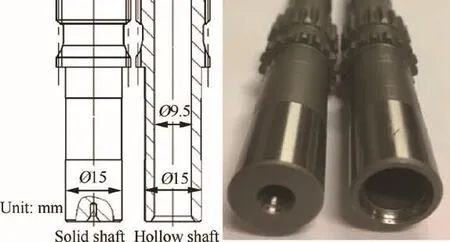
Fig.10 Dimensions of splined shafts.
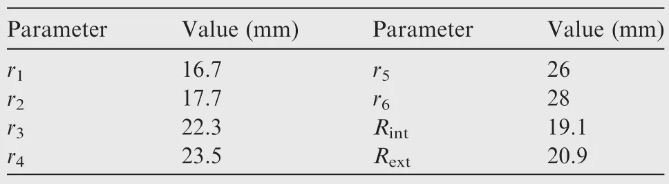
Table 4 Dimensions of sealing lands and sector pads.
(2)Mx_tandMy_t:Because of the centrosymmetric distribution of the sector pads,the moments ofMx_tandMy_tare always in the direction opposite to the tilting to prevent a further enlargement of the tilt angle.The simulated pressure and gap distributions at the cylinder rotation angle θ1=0°in Fig.13 also indicate that the location of the peak pressure caused by the thermal wedge effect corresponds to that of the minimum gap height where a green arrow points to.Therefore,the moment direction ofMy_tis opposite to that ofMx_sealat any time.From the moment direction variation ofMx_t,it can be deduced that the changed tilt direction is the main cause of the descent ofMy_seal.
(3)Mx_shaftandMy_shaft:Due to the assumptions in this paper,the moment directions ofMx_shaftandMy_shaftare opposite to the cylinder tilt direction.At the cylinder rotation angle θ1=0°,Mx_pandMx_sare in the negative direction whileMx_cis positive.As the speed rises,the increasingMx_cgradually counterbalancesMx_pandMx_s,and then exceeds the summation of them.That is why the magnitude ofMx_shaftdecreases at first and then rises in the direction opposite to that ofMx_c,which indicates that the moment created by the centrifugal force exerts a dominant influence on the cylinder tilt behaviour at a high speed.As the magnitude ofMy_sealdecreases with the speed in the preceding analysis,My_shaftincreases to counterbalanceMy_p.Besides the tilt direction,the tilt angle is estimated to reach the lowest value at a speed of 9000 r/min where both the values ofMx_shaftandMy_shaftare close to zero.
As for the impacts of the splined shaft bending rigidity,theMx_tandMy_tmagnitudes of the solid shaft are lower than those of the hollow shaft,representing that the tilt angles of the hollow shaft are larger than those of the solid shaft.Nevertheless,theMy_shaftmagnitude of the solid shaft is higher,which implies that the solid shaft is able to bear a higher load and generate a smaller deflection.
4.2.Simulated cylinder tilt behaviour
The simulated central gap height,tilt angle,and azimuth of the minimum gap height as a function of the speed at the cylinder rotation angle θ1=0°are plotted in Fig.14.A phase difference of 180°exists between the azimuth angle of the thinnest oil film and the tilt azimuth angle θα.It is clearly seen that the central gap height increases almost linearly with the speed because the improved hydrodynamic and thermal wedge effects push the cylinder away from the valve plate.Then,it is important to notice that the trends of the tilt angles and minimum gap height locations are consistent with the variations of the moments acting on the cylinder.The curves of the tilt angles have negative slopes until reaching the same operating points where the magnitudes of bothMx_shaftandMy_shaftare close to zero.The curves of the minimum gap height locations also show transitions when the speed reaches 9000 r/min.At the transition point,the cylinder is almost parallel to the valve plate,and the thinnest oil film is predicted to be at the azimuth angle of about 68°on the high-pressure side.For a speed ranging from 5000 r/min to 8000 r/min,the cylinder is predicted to tilt towards the high-pressure side and be close to the inner dead point;at a speed of 10,000 r/min,it is prone to tilt towards the outer dead point.The simulated results indicate that the operating conditions for a given cylinder to rotate steadily are limited in a range.
The comparison between the solid and hollow shafts denotes that the splined shaft bending rigidity has little influence on the height values and tilt azimuth angles,but affects the tilt angles slightly.The tilt angles are within a range of 0.0001°-0.0035°,and their maximum disparity between the solid and hollow shafts is less than 0.0005°,which is in agreement with the trivial differences ofMx_shaftandMy_shaftbetween the two shafts.
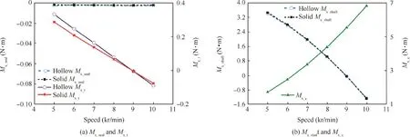
Fig.11 Simulated moments about the X2axis on balanced cylinder at outlet pressure ps=7 MPa.
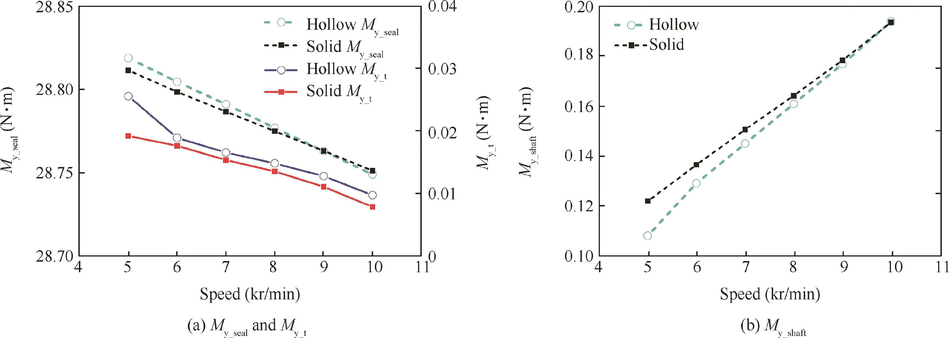
Fig.12 Simulated moments about the Y2axis on balanced cylinder at outlet pressure ps=7 MPa.
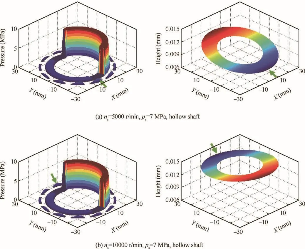
Fig.13 Simulated pressure and gap height distributions for cylinder/valve plate interface.
4.3.Comparison between simulated and experimental results
The simulated azimuths of minimum gap heights as a function of the cylinder rotation angle at 10000 r/min,7 MPa with the hollow shaft are shown in Fig.15.A sudden change of the azimuth at θ1=25°results from a decrease in the number of cylinder chambers connected with the outlet.The EHA pump prototype was dismantled to detect the valve plate surface after running for 30 min at the same operating condition.As shown in Fig.15,a very light scratch was found close to the outer dead point on the high-pressure side.The results show that the simulated azimuth angles roughly correspond to the actual wear location on the valve plate.
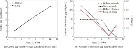
Fig.14 Simulated results of cylinder tilt behaviour for different speeds at outlet pressure ps=7 MPa.
The simulated gap flow between the cylinder and the valve plate and the measured case drain flow are drawn in Fig.16.It is obvious that both the simulated gap flows and the measured leakages increase almost linearly as a function of the speed,even though the simulated cylinder tilt angles vary in a nonlinear way.Due to the inconspicuous disparity of the simulated tilt angles between the solid and hollow shafts,the gap flow curve of the solid shaft almost coincides with that of the hollow shaft.Meanwhile,the variation of the measured case drain flow between the solid and hollow shafts is less than 0.1 L/min,resulting in a tiny difference of the volumetric efficiencies between them,as found in Fig.17(a).The measured results agree with the simulated ones,and a conclusion that lowering the splined shaft bending rigidity can slightly raise the cylinder tilt angle without affecting the volumetric efficiency can be obtained.
It is also important to point out that the mechanical ef ficiencies of the hollow shaft are found experimentally to be 0.6-2.4%lower than those of the solid shaft,and an increment of the measured input torques is the direct cause,as shown in Fig.17(b).In addition,the reduced amount of the mechanical efficiency reaches the peak at 5000 r/min,where the increment of the simulated tilt angle between the solid and hollow shafts is the highest,while the simulated central gap height is the lowest.This is because the slightly enlarged tilt angles caused by a lower splined shaft bending rigidity increase the frictional losses of the cylinder/valve plate friction pair dramatically.Ultimately,the overall efficiencies of the solid shaft in the experiments are 0.7-2.1%higher than those of the hollow shaft.Hence,to achieve a weight loss without reducing the mechanical efficiency,the dimensions of the cylinder/valve plate interface need to be redesigned by using a method in which the effects of the splined shaft bending rigidity are taken into account.
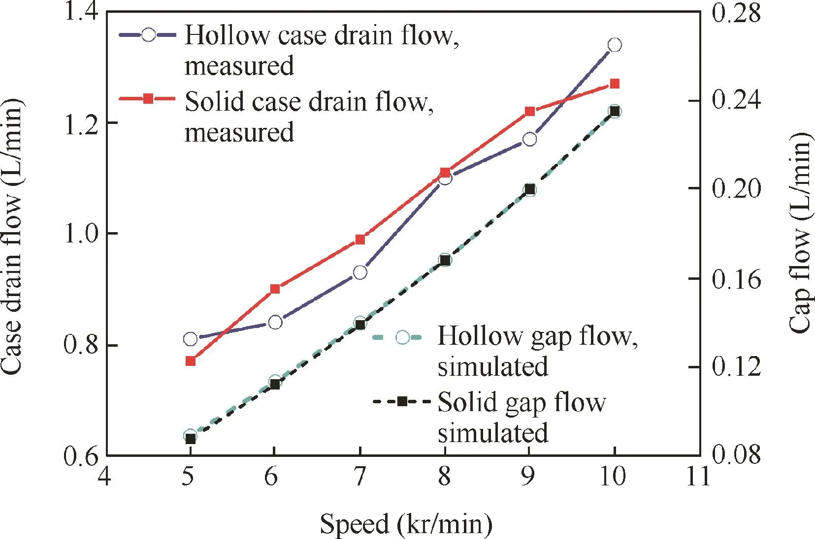
Fig.16 Simulated gap flow between cylinder and valve plate and measured case drain flow of tested prototype at outlet pressure ps=7 MPa.
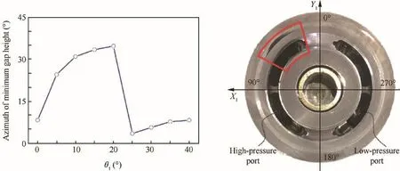
Fig.15 Simulated cylinder tilt azimuths at outlet pressure ps=7 MPa and shaft speed ns=10000 r/min(left)and worn valve plate of tested prototype(right).
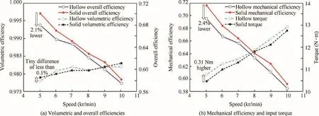
Fig.17 Efficiencies and input torques of tested prototype at outlet pressure ps=7 MPa.
5.Conclusions
A cylinder tilt behaviour-predicting model considering the splined shaft deflection is established.The moments exerted by the splined shaft are included in the model by establishing a quantitative relationship between the magnitude and direction of the splined shaft deflection,the cylinder tilt angle,and the tilt azimuth angle.A flow rate equation in combination with the cylinder tilt behaviour is built to calculate the gap flow of the cylinder/valve plate friction pair.Numerical and experimental investigations based on an EHA pump prototype are performed with a broad range of operating points,and the following conclusions are drawn:
(1)Employing a hollow shaft instead of a solid one achieves a weight saving of 29.7%and almost has no influence on the volumetric efficiency of the tested prototype,but reduces the mechanical efficiency of the prototype by 0.6-2.4%.The experimental phenomena can be explained by the trivial differences of the simulated central gap heights between the two shafts and the enlargement of the simulated tilt angles by the hollow shaft.
(2)Both the simulated gap flows of the cylinder/valve plate interface and the measured case drain flows of the prototype increase almost linearly as a function of the speed,even though the simulated cylinder tilt angles vary in a nonlinear way.
(3)The actual wear location on the valve plate of the prototype running for 30 min at 10000 r/min,7 MPa with the hollow shaft was close to the outer dead point on the high-pressure side,which roughly corresponds to the simulated azimuths of minimum gap heights.
(4)In the future,a more specific relationship between the cylinder tilt behaviour and the splined shaft deflection needs to be established,and the micro motion of the cylinder in the EHA pump needs to be measured to provide a direct evidence for conclusions.
Acknowledgements
The authors would like to appreciate the financial supports received from the National Basic Research Program of China(973 Program)(No.2014CB046403)and the National Natural Science Foundation of China(Nos.U1509204 and 51605425).
 CHINESE JOURNAL OF AERONAUTICS2019年2期
- CHINESE JOURNAL OF AERONAUTICS的其它文章
- Guide for Authors
- Special Issue call for papers: Emerging Technologies of Unmanned Aerial Vehicles
- Identification of the state-space model and payload mass parameter of a flexible space manipulator using a recursive subspace tracking method
- Efficiency optimized fuel supply strategy of aircraft engine based on air-fuel ratio control
- Event-triggered adaptive control for attitude tracking of spacecraft
- Reliable flight performance assessment of multirotor based on interacting multiple model particle filter and health degree