
Investigation on a vertical radial flow adsorber designed by a novel parallel connection method☆
2018-05-26 07:29:04ZhengshuDaiMengYuDaozheRuiXuejunZhangYangZhao
Zhengshu Dai,Meng Yu ,Daozhe Rui,Xuejun Zhang ,*,Yang Zhao
1 School of Energy and Power Engineering,University of Shanghai for Science and Technology,Shanghai 200093,China
2 Key Laboratory of Refrigeration and Cryogenic Technology of Zhejiang Province,Institute of Refrigeration and Cryogenics,Zhejiang University,Hangzhou 310027,China
1.Introduction
Large-scale cryogenic air separation systems have attracted considerable attention in recentyears,due to the increasing demand for industrial gas.Purification plays an important role in cryogenic air separation systems.It contributes to the elimination of high freezing-point contaminants in the air from previous processes,such as water vapor and carbon dioxide,which could cause problems like freeze-up and explosion[1].Vertical radial flow adsorbers are widely used in purification process of large-scale cryogenic air separation systems.The non-uniformity of air flow distribution in vertical radial flow adsorbers[2,3]has a bad effect on the utilization efficiency of adsorbents.Reforming the structure of the vertical radial flow adsorber is considered as one of the most effective ways to solve the above problem.
From the open literatures,researches have studied on optimizing the air flow distribution in vertical radial flow reactors,which have similar structures as vertical radial flow adsorbers used in large-scale cryogenic air separation systems.Zhang et al.[4]proposed a reasonable design of the uniform fluid distribution device for radial flow reactors.It was based on the measurements of momentum exchange coefficient and perforated resistance coefficients of the divided flow channel and combined flow channel.Chang and Calo[5]carried out a theoretical study to reveal the effect on the air flow distribution caused by four flow configurations in a radial flow fixed-bed reactor.Chang et al.[6]pointed out that uniform flow distribution in a radial flow fixed bed reactor could be obtained by adjusting the dimensions of the reactor.Yoo and Dixon[7]proposed a hydrodynamic model to investigate the im-pactfactors on the flow distribution in a mixed- flow reactor.The results showed that the flow distribution was mainly determined by inlet Reynolds number of air in the center pipe,ratio of center pipe cross-sectional area to annulus cross-sectional area,and ratio of bed resistance to flow resistance.Ponzi and Kaye[8]found that the non-uniformity of air flow distribution had a bad effect on the predicted conversion and selectivity in a radial flow fixed-bed reactor.Kareeri et al.[9]found that the ratio of the center pipe cross-sectional area to that of the annular channel has a significant effect on the flow distribution in a radial flow reactor using Computational Fluid Dynamics(CFD).Li and Zhu[10]got the conclusion that the uniformity of the pressure profiles in the distributing channels and collecting channels in the axial direction has a significant effect on the flow distribution of each layer.Zhang et al.[11]derived a differential equation by pressure drop analysis in the Z- flow type radial flow adsorber with a cone in the middle of the central pipe.The differential equation determined the ideal cross-sectional radii of the cone along the axis and provided theoretical support for designing Z- flow type radial flow adsorber.Farsi[12]conducted research on reactors with new configurations,and compared the new configurations with the conventional tubular reactors.It was found that production capacity was improved about 2.8%and 3.7%respectively in one-stage and two-stage membrane configurations.Hamedi et al.[13]presented comparisons among a conventional packed bed axial flow reactor,an optimized axial flow reactor and a novel optimized packed bed radial flow reactor.
From the literatures mentioned above,it could be seen that reforming the vertical radial flow reactors structurally could result in better performance of the reactors.Since there are few research found in reforming the structure of the vertical radial flow adsorbers used in large-scale cryogenic air separation systems,a novel parallel connection method was proposed to design the vertical radial flow adsorber in the present work,so as to overcome the non-uniformity of air flow distribution in the adsorber.Experimental apparatus was designed and constructed,and a CFD-based model was developed using commercial software Fluent.The model was verified with experimental data,and simulation results of air flow distribution,the static pressure drop and the radial velocity in the newly designed adsorber were obtained.Comparisons were also made between the height-increasing method and the parallel connection method.Finally,the geometric parameters of annular flow channels and the adsorption bed thickness of the upper unit in the parallel-connected vertical radial flow adsorber were optimized so that the air could penetrate the upper and lower adsorbents simultaneously.
2.Numerical Modeling and Validation
2.1.Geometric model
The traditional vertical radial flow adsorber generally includes a center pipe,an internal porous cylinder,an adsorption bed,an external
if ned as Y direction,and the origin of coordinate was set at the central bottom of the adsorber.The structured quadrilateral grid of the computational domain was generated by Gambit 2.4.6 and the near-wall mesh was re fined,as illustrated in Fig.2(b).

The equal cross-sectional area model was adopted,ensuring that the outer annulus could be divided into two flow channels with the same cross-sectional area,thus the upper and lower unit could have the same adsorption capacity.Eq.(1)should be satisfied as obtaining the radius of the upper external porous cylinder R1:porous cylinder and an outer annulus.From the axial flow direction,the air flow in center pipe and outer annulus could be parallel flow(Z- flow)or counter flow(Π- flow).From the radial flow direction,the air flow directions could be centripetal(CP)or centrifugal(CF).The CP-Z air flow type configuration was adopted in the present work.
The schematic diagrams of CP-Z vertical radial flow adsorbers are shown in Fig.1.In order to increase the air treatment capacity of the traditional adsorber[shown in Fig.1(a)],height-increasing method and parallel connection method were adopted to increase the treatment capacity of air in the adsorbers,as shown in Fig.1(b)and(c).An internal deflector,an external deflector and a middle baffle are used to separate the adsorption bed independently into the upper and lower units with parallel connection method.For the purpose of comparison,the following assumptions were made:1)The adsorption bed thickness in Fig.1(b)remains the same as that in Fig.1(a).The cross-sectional area of outer annulus and the adsorption bed height in Fig.1(b)are doubled,compared with those in Fig.1(a).2)The height of the upper and lower units in Fig.1(c)keeps the same as that in Fig.1(a).The cross-sectional area of outer annulus and the adsorption bed thickness of the lower unit in Fig.1(c)remain the same as those in Fig.1(b).The adsorption bed thickness of upper unit was determined by the volume of adsorbents.3)The inlet air velocities in Fig.1(a),(b)and(c)are the same.
Since the configuration of the adsorber designed by parallel connection method is axisymmetric,half of the adsorber was adopted when developing the geometric model,as shown in Fig.2(a).The axial flow direction was defined as X direction,the radial flow direction was de-
The radius of upper internal porous cylinder R2could be determined by Eq.(2),thus the upper unit and the lower unit could have the same volume of adsorbents.


Fig.1.The schematic diagrams of CP-Zvertical radial flow adsorbers.1—center pipe,2—internal and external porous cylinders,3—outerannulus,4—adsorption bed,5—internal deflector,6—middle baffle,7—external deflector.
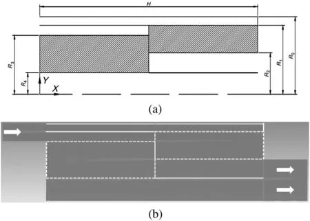
Fig.2.Schematic of the geometric model and the computational mesh for the numerical analysis.
Geometric parameters of the adsorber are listed in Table 1.

Table 1 Geometric parameters of the adsorber
2.2.Governing equations
The adsorbents inside the adsorber could be considered as porous media which would have a great effect on the air flow characteristics.As a consequence,the regions in the adsorber could be classified into two sections.Section 1 is the flow channels without adsorbents,while Section 2 is the adsorption bed with adsorbents.
The governing equations of Section 1 are represented as follows.
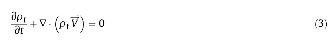
The continuity equation:
The momentum equation:

whereis the stress tensor(kg·m·s?2);is the volume force acting on a unit mass of fluid(N·m?3);ρfis the air density(kg·m?3);is the air velocity(m·s?1);p is the static pressure(Pa).
The porous media model is coupled with the governing equations of Section 2[14],details are as follows.
The continuity equation:

The momentum equation:
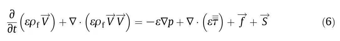
whereis the momentum source term related to porous media(Pa·m?1);ε is the bed porosity.
The momentum source term in Eq.(6)was calculated by the following eqs[14,15].:

where μ is the dynamic viscosity(Pa·s);α is the permeability(m2);C1is the inertial resistance coefficient(m?1);smis the mass source term caused by adsorption process(kg·m?3·s?1).
The first term in Eq.(7)is the Darcy term which represents the resistance in porous media.The second term in Eq.(7)is the Forchheimer term which is regarded as the modification of Darcy term.The third term in Eq.(7)is the momentum variation caused by adsorption process.Under the typical operating condition of adsorber(p=0.6 MPa,T=288.15 K),the mass fractions of water vapor and carbon dioxide in air are 0.061%and 0.457%respectively.The ratio of the third term to the firstterm is 5.08×10?5by calculation,which could be negligible.As a result,it is reasonable to neglect the third term and concentrate on the first and the second term.The airvelocity was determined by the air flow rate and the cross-sectional area of the adsorber.Other parameter values in Eq.(7)are listed in Table 2.
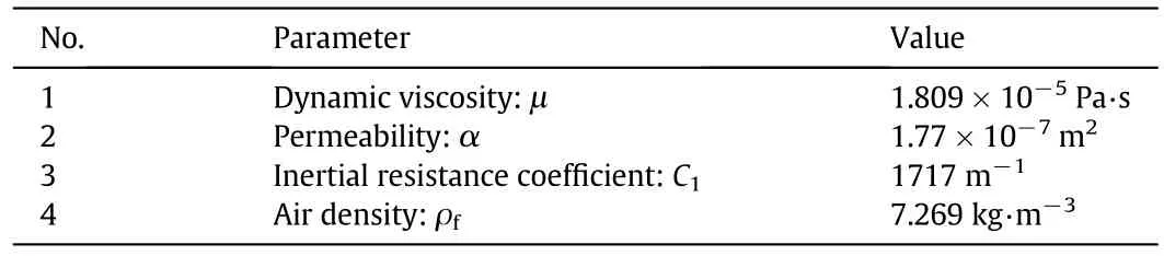
Table 2 The parameter values under the typical operating condition
2.3.Boundary conditions and initial conditions
The boundary condition of inlet is the velocity-inlet type with air flow rate 550 m3·h?1and initial temperature 298.15 K,while the outlet is the pressure-outlet type boundary condition with outlet pressure 0.1 MPa.The air is considered as an incompressible fluid due to its relatively low velocity.The density and the dynamic viscosity of the air in the adsorber under the conditions of 298.15 K and 0.1 MPa are 1.1685 kg·m?3and 1.8492 × 10?5Pa·s respectively.All the walls are considered stationary without slipping,and the standard wall functions were adopted to deal with the conditions near walls.
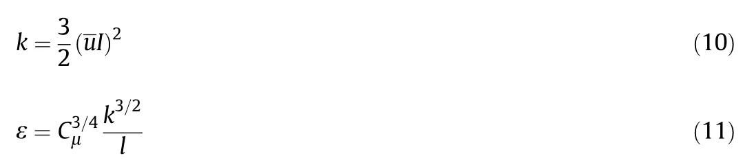
The turbulence parameters under the inlet and outlet conditions are turbulent kinetic energy(k)and turbulent dissipation rate(ε),which could be calculated by the following equations:where I is the intensity,which could be represented as I=0.16×R e?1/8and the Reynolds number should be calculated by the maximum velocity of the air in the specific cross-sectional area;l is the turbulence length scale,which could be calculated by hydraulic diameter L with the equation l=0.07 L;Cμis the empirical constant in the turbulence model,which takes the value as 0.09;u represents the average velocity at some specific cross-sectional area(inlet and outlet).
The hydraulic diameter above was determined to be replaced by the equivalent diameter[16].Table 3 shows the inlet and outlet conditions of the air in the adsorber.Furthermore,the porous-jump model was selected to treat the internal and external porous cylinders,and the specific parameter values are listed in Table 4.

Table 3 The inlet and outlet parameter values of the air in the adsorber
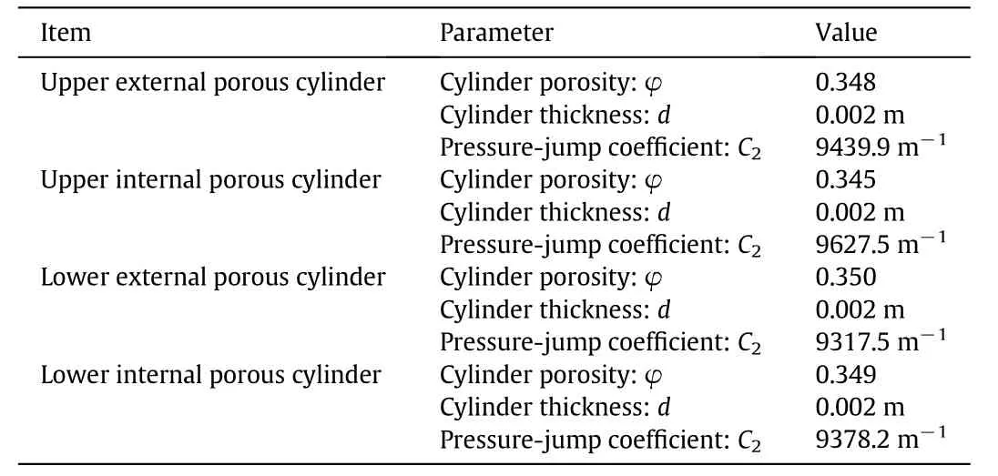
Table 4 The porous-jump parameter values of internal and external porous cylinders
The pressure-jump coefficient C2could be calculated by the following equation:

where c is the orifice discharge coefficient,equals to 0.62 in the present work[9]as reference.
2.4.Solution methods
The SIMPLE algorithm was used to solve the pressure–velocity coupled equations.The standard k-ε model was adopted.The PRESTO!interpolation algorithm was chosen to solve the pressure term.The first order upward discretization scheme was given to solve the convection term.The central difference method was selected to solve the diffusion term.Convergence standard for all the equation residuals were set within 10?5.
2.5.Grid independence analysis
In order to select suitable grid quantity for a better computational accuracy,the grid independence analysis has been conducted.The mesh was set with six different grid quantities from 25000 to 158000,respectively.Fig.3 shows the calculating pressure at external porous cylinder with the height of 0.3 m,and it could be seen that the percentage difference of pressure calculating at 111376 cells from that using 142360 cells is 0.008%,which means that increasing grid cell number has ignorable effect on improving calculation precision.Thus,the mesh with a cell number of 111376 was chosen in the present work.
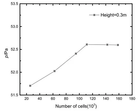
Fig.3.Grid independence analysis.
2.6.Validation of the CFD model
In order to verify the reliability of the above model,experiments were carried out for adsorbers designed by both height-increasing method and parallel connection method.Fig.4 shows the experiment apparatus of CP-Z flow type vertical radial flow adsorber.The experimental system mainly consists of the air compressor,buffer tank, flow meter,CP-Z flow type vertical radial flow adsorber and pressure measurement system.The air is sent into the pipe of the experimental system by an air compressor after removing large particles of impurities from the air by a filter screen,then it enters into the bottom of the adsorber after being stable in a buffer tank and finally flows through the entire adsorber before being discharged from the top of the adsorber.The experiment was carried out at normal pressure and temperature,and the flow rate was regulated by coarse adjustment(valve 1)and fine adjustment(valve 2)in order to maintain the stability of the specific flow rate.Several measurements were set at different height along the axial flow direction of the adsorber.Too many measuring points set will definitely destroy the original flow distribution inside the adsorber,thus a flexible pressure guide measuring system was designed in order to avoid that.The measuring point could be adjusted continuously along the pressure guide pipe in the adsorber height direction.There are three pressure guide measuring devices inside the adsorber,which means that three pressure data could be obtained at each measuring height to ensure the accuracy.Each measuring device consists of a guide rail,a sealing wood and a pressure guide pipe,shown in Fig.5.The guide rail was fixed and the flexible pressure guide pipe was installed inside the guide rail,and the pressure guide pipe was connected with the differential pressure transmitter.The air at the measuring points of the internal and external porous cylinders of the adsorber at different height could be obtained and guided to the differential pressure transmitter by sliding the pressure guide pipe in the guide rail.The radial static pressure drop between the internal and external porous cylinders at different height could be measured by the differential pressure transmitter.

Fig.4.Experiment apparatus of CP-Z flow type vertical radial flow adsorber.1.Air compressor,2.Valve 1,3.Valve 2,4.Buffer tank,5.Flow meter,6.CP-Z flow type vertical radial flow adsorber,7.Pressure measurement system.
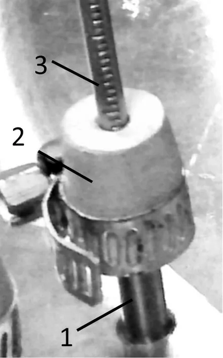
Fig.5.Flexible pressure guide measuring device.1—Guide rail;2—Sealing wood;3—Pressure guide pipe.
The CFD-based model was adopted to obtain the variations of the radial static pressure drop between the internal and external porous cylinders with the height of the adsorbers designed by height-increasing method and parallel connection method at the same inlet flow rate(550 m3·h?1)respectively.Figs.6 and 7 show the comparisons between the experimental data and simulation results.Δp represents the radial static pressure drop between the internal and external porous cylinders,and H represents the height of the adsorbers.From Figs.6 and 7,it could be concluded that the variation trend of Δp with H for both the simulation results and the experimental data are almost the same,but there still exists slight differences between values for the experimental data and the simulation results(31.78 Pa–58 Pa).

Fig.6.Variation of the radial static pressure drop between the internal and external porous cylinders with the height of the adsorber designed by height-increasing method.

Fig.7.Variation of the radial static pressure drop between the internal and external porous cylinders with the height of the adsorber designed by parallel connection method.
The slight deviations between the experimental data and the simulation results may be caused by two aspects:the experimental measurement and the simulation simplification.From the experimental measurement aspect,some measurement errors could not be avoided.The total error of the pressure measurement system is±13 Pa,including the calibration error(±1 Pa),the differential pressure transmitter error(±10 Pa)and the random error(±2 Pa).The full scale of the differential pressure transmitter is 250 Pa,and the measurement range in the experiment is from 20 to 80 Pa,which is relatively small compared to the full scale,and this will lead to larger measurement errors caused by the differential pressure transmitter.The total error of the flow meter is ±17.25 m3·h?1,including the calibration error(±0.75 m3·h?1),the flow sensor error(±15 m3·h?1)and the random error(±1.5 m3·h?1).From the simulation aspect,simplifications were made in the model:1)The adsorption bed porosity is assumed to be a constant value during simulation rather than a variable in actual experiment.Along the radial flow direction,the porosity on the edge of the adsorption bed is larger than that in the center of the adsorption bed.In axial flow direction,the porosity of the upper adsorption bed is larger than that in the lower adsorption bed due to the gravity effect of the adsorbants and the air flow effect through the adsorbants.2)The momentum source term in the porous media model could not comprehensively express the disturbance effect of adsorbants on the air flow.In the experiment,the disturbance effect not only exists in radial flow direction but also exists in axial flow direction,and the disturbance effect occurred in axial flow direction is not considered in the simulation.
From the above analysis,it could be seen that some of the errors could not be avoided,and those are the main reasons for the existence of the slight deviations between the experimental data and the simulation results.But obviously the variation trend for experimental data and simulation results could match perfectly with each other.The conclusion could be drawn that the CFD-based model could be considered as a reliable model.
3.Results and Discussion
In this section,simulation results are obtained by the reliable CFD-based model.The air flow distribution and radial velocity along the height direction of the adsorber are discussed,and comparisons are made between the height-increasing method and the parallel connection method.Finally,the optimal geometric parameters of annular flow channels and the optimal adsorption bed thickness ratio of the upper and lower units are also obtained.
3.1.Comparison of the flow field characteristics
Fig.8 shows the comparison of radial static pressure drop variation along the height of the adsorbers designed by height-increasing method and parallel connection method as the inlet flow rate is 550 m3·h?1.It could be observed that the static pressure drop along the height of the adsorber designed by the height-increasing method ranges from 4.4 Pa to 446 Pa and increases at an increasing speed.While the static pressure drop along the height of the adsorber designed by the parallel connection method ranges from 13.7 Pa to 74.6 Pa and increases at a much slower speed.Asharp decline could be observed in the middle position of the adsorption bed height,this discontinuity is caused by the independence between the upper and lower units of the adsorber.In addition,as the adsorption bed height is from 0 m to 0.25 m,the static pressure drop along the adsorber height in the adsorber designed by the parallel connection method is larger than that of using the height increasing method.The reason is that more air passes through the lower unit of the adsorber designed by the parallel connection method compared with the adsorber designed by the height-increasing method,which is beneficial to the uniformity of the flow distribution.
To ensure the uniformity of the air distribution along the height of the adsorber,the static pressure drop between the internal and external porous cylinders should be kept constant along the axial flow direction of the adsorption bed[17].That is to say the ideal static pressure drop should be a horizontal line shown in Fig.8 if the air distribution along the axial flow direction of the adsorption bed is completely uniform.However,from Fig.8,it could be seen that the static pressure drop along the axial flow direction of the adsorber designed by the height increasing method severely deviates from the ideal one.The difference between the maximum and minimum static pressure drop is 441.6 Pa by using the height-increasing method,which could hardly reach the industrial standards.The difference between the maximum and minimum static pressure drop by using the parallel connection method is 60.9 Pa and it is reduced by 86.2%compared with that of using the height-increasing method.Moreover,the upper unit of the adsorber designed by the parallel connection method has much lower static pressure drop compared with that of the adsorber designed by the height increasing method.As a consequence,the energy consumption is effectively reduced when the air passes through the adsorption bed as the parallel connection method is adopted.

Fig.8.Comparison of radial static pressure drop variation along the height of the adsorbers designed by height-increasing method and parallel connection method.
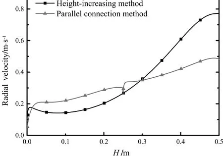
Fig.9.Comparison of radial velocity variation along the height of the adsorbers designed by height-increasing method and parallel connection method.
Fig.9 shows the comparison of the radial velocity at the external porous cylinder of adsorbers designed by the height-increasing method and parallel connection method as the inlet flow rate is 550 m3·h?1.From Fig.9,it could be clearly seen that the range of the radial velocity at the external porous cylinder of adsorber designed by the parallel connection method(from 0.054 m·s?1to 0.471 m·s?1)is narrower than the velocity range at the external porous cylinder of adsorber designed by the height-increasing method(from 0.141 m·s?1to 0.771 m·s?1).The variation of radial velocity at the external porous cylinder of adsorber designed by the parallel connection method has a discontinuity in the middle position of the adsorption bed height,which is similar to the variation of static pressure drop shown in Fig.8.The comparison of the radial velocity variation along the height of the adsorbers designed by two different methods indicates that the radial velocity at the external porous cylinder of adsorber designed by the parallel connection method is much more uniform,which means that the air distribution along the height of the adsorber could be much more uniform,and the maximum radial velocity at the top of the adsorber designed by the parallel connection method is reduced by 39%compared with that of using the height-increasing method.
3.2.Comparison of the uniformity
On account of the fact that the radial velocity is not only the function of the pressure drop between the internal and external porous cylinders,but also the function of the axial velocity in the center pipe and outer annulus.Therefore,a quantitative measurement of uniformity M for the axial flow distribution at a certain cross section is defined[18–20]as follow:
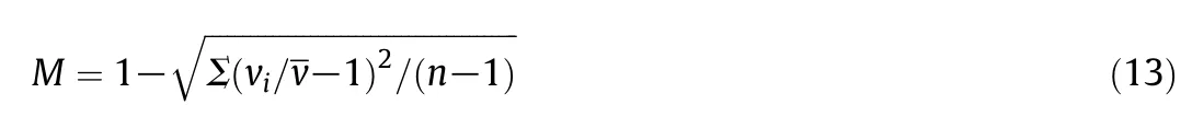
where viis the radial velocity of the air at a certain annular cross section(m·s?1);n is the measuring number of the data points;is the average radial velocity of the air at a certain annular cross section(m·s?1).
From the definition of uniformity M,it could be concluded that the greater uniformity M could lead to more uniform air distribution along the height of adsorber.The uniformity M at the external porous cylinder of the adsorber designed by the parallel connection method is 0.70,and the uniformity is improved by 80%compared with the uniformity M(0.39)of the adsorber designed by the height-increasing method.Aconclusion could be drawn that the air could pass through the external porous cylinder more uniformly by using the parallel connection method,which is beneficial to the air distribution in the adsorption bed.
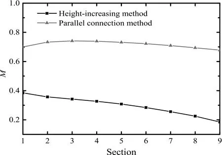
Fig.10.Comparison of the uniformity M on certain cross sections by using the parallel connection method and height-increasing method.
In order to clearly show the variation of the air uniformity in the adsorption bed,nine annular cross sections were established from outside to inside direction,and the cross sections were denoted as section-1 to section-9.The uniformity M of every annular cross section of the adsorber designed by the parallel connection method and height increasing method were calculated by Eq.(13)and the results are shown in Fig.10.The uniformity M varies slightly along the radial direction of the adsorber designed by the parallel connection method,and maintains at a higher level at all the cross sections compared with that of the adsorber designed by the height-increasing method.It is noteworthy that the uniformity M of the air distribution inside the adsorber designed by the height-increasing method decreases along the radial flow direction.The reason is that the flow inside the adsorption bed is two-dimensional,the air flows to the top of the adsorber along the axial flow direction and passes through the adsorption bed along the radial flow direction at the same time which makes the uniformity M decrease.However,in the case of using the parallel connection method,the middle baffle could effectively weaken the axial air flow between the upper and lower units,which avoids the deterioration of the air distribution and maintains the uniformity M at a relatively high level.
3.3.Optimization of geometric parameters of annular flow channels
In this section,the equal hydraulic radius model was established to optimize the geometric parameters of annular flow channels,and comparisons are made with the equal cross-sectional area model mentioned in Section 2.1.
The hydraulic radius of the upper and lower unit is 21 mm in the equal hydraulic radius model since the entire hydraulic radius of annular flow channels is 42 mm.The parameters of the lower unit are kept unchanged,while the parameters of the upper unit will be adjusted.After adjustment,it could be found that the cross-sectional area of annular flow channel in the upper unit is larger than that in the lower unit.As a result,the radius of upper internal porous cylinder R2could be determined by Eq.(14)in order to match the adsorption capacity of adsorbents in the upper and lower unit.Geometric parameters of the equal hydraulic radius model are listed in Table 5.


Table 5 Geometric parameters of the equal hydraulic radius model
Fig.11 shows the comparison of the radial velocity at the external porous cylinder along the height of the adsorbers by using different models as the inlet flow rate is 750 m3·h?1.From Fig.11,it could be clearly seen that the radial velocities at the external porous cylinder using the equal hydraulic radius model are higher than those of using the equal cross-sectional area model in the lower unit,while the radial velocities at the external porous cylinder using the equal hydraulic radius model are lower than those using the equal cross-sectional area model in the upperunit.It indicates that the radial velocity at the external porous cylinder using the equal hydraulic radius model is much more uniform.The reason for that is there is more resistance in the upper unit due to the thicker adsorption bed compared with the equal cross-sectional area model.Consequently,the uniformity of the adsorber is improved when more air passes through the lower unit and less air passes through the upper unit.

Fig.11.Comparison of radial velocity at the external porous cylinder along the height of the adsorbers by using equal cross-sectional area model and equal hydraulic radius model.
In order to clearly show the variation of the air uniformity in these two models, five annular cross sections were established from outside to inside direction and the cross sections were denoted as section-1 to section-5.The uniformity M of every annular cross section of the adsorberby using equal cross-sectional area model and equal hydraulic radius model were calculated by Eq.(13)and the results are shown in Fig.12.The uniformity M increases at the beginning and then decreases slightly by using equal cross-sectional area model.The uniformity M maintains at a higher level from section-1 to section-3 and then decreases sharply by using equal hydraulic radius model.It is noteworthy that the uniformity M at the internal porous cylinder by using equal hydraulic radius model is lower than that by using equal cross-sectional area model.The reason is that the adsorption bed thickness of the upper unit using equal hydraulic radius model is much thicker than that of using equal cross-sectional area model,which could lead to lager surface area contraction.Meanwhile,lager surface area contraction means higher air velocity which is not conducive to the uniformity M,as shown in Fig.13.However,the uniformity M from section-1 to section-3 are more significant since the adsorption bed is cylindrical,which means the amount of adsorbents from outside to inside is gradually reduced.Therefore,the geometric parameters of annular flow channels using equal hydraulic radius model is superior to that of using equal cross-sectional area model.

Fig.12.Comparison of the uniformity M on certain cross sections by using equal cross sectional area model and equal hydraulic radius model.

Fig.13.Comparison of radial velocity at the internal porous cylinder along the height of the adsorbers by using equal cross-sectional area model and equal hydraulic radius model.
3.4.The optimization of the adsorption bed thickness ratio
The equal cross-sectional area model of the adsorber designed by the parallel connection method was established by filling the equivalent volume of adsorbents in the upper and lower units.The adsorption bed of the upper unit is thinner and the penetration resistance is smaller than that of the lower unit.The treatment capacity of air in the upper unit thus is much larger than that in the lower unit,the adsorbents in the upper and lower units could not be used efficiently.Optimizing the adsorption bed thickness of the upper unit could make both units be penetrated simultaneously by the air flow and improve the efficiency of using the adsorbents in adsorption space in both units.
Further studies were conducted to determine the optimal upper unit bed thickness.To simplify the problem,some assumptions were made:1)keep the parameters of the lower unit unchanged;2)the optimization was conducted based on the equal hydraulic radius model.Consequently,the adsorption bed thickness could be optimized by changing the diameter of the upper internal cylinder,and the adsorbent filling ratio of the upper and lower units equals to the designed air flow rate ratio of the upper and lower units.
Based on the above assumptions, five geometric models of the adsorbers designed by the parallel connection method were established,namely A,B,C,Dand E.The specific parameters of the geometric models are shown in Table 6,Qdis the adsorbent filling ratio of the upper and lower units as well as the designed air flow rate ratio of the upper and lower units,δ is the adsorbent bed thickness ratio of the upper and lower units,see Eq.(15)and Eq.(16).where A is the adsorption bed radial cross-sectional area(mm2);H is the height of the adsorption bed(mm);subscripts u and l represent the upper unit and the lower unit respectively.


Table 6 Parameters of five geometric models
The radial velocity distribution of the air at the external porous cylinder was obtained by simulation for the five different geometric models.Fig.14 shows the effect of adsorbents filling ratio on radial velocity at the external porous cylinder along the height of adsorbers with five geometric models.It could be seen that the radial velocity in the lower unit(0–0.25 m)increases with the increase of the adsorbents filling ratio,and the radial velocity in the upper unit(0.25–0.5 m)decreases with the increase of the adsorbents filling ratio.The average radial velocity ratios between the upper and lower units in five geometric models could be obtained by averaging the integrals of the radial velocity of the air at the external porous cylinder along the height of adsorbers,results are shown in Table 7.

Fig.14.Effect of adsorbents filling ratio on radial velocity of the air at the external porous cylinder along the height of adsorbers with five geometric models.
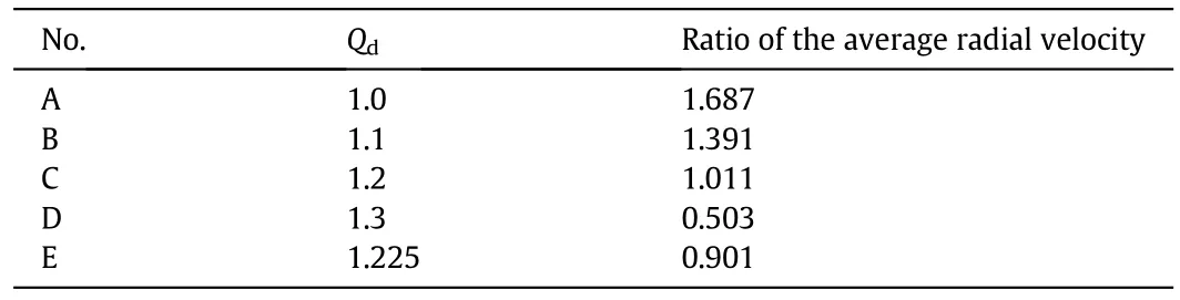
Table 7 Average radial velocity ratios between the upper and lower units in five geometric models
The actual air flow rate ratio of the upper and lower units equals to the ratio of the average radial velocity at the external porous cylinder of the upper and lower units multiplied by the ratio of the surface area of the external porous cylinder,as represented in Eq.(17):
whereis the average radial velocity of the air at the external porous cylinder(m·s?1);A′is the surface area of the external porous cylinder(mm2);subscripts u and l represent the upper unit and lower unit respectively.
By Eq.(17),the actual air flow rate ratios between the upper and lower units in five geometric models could be calculated,shown in Table 8.

Table 8 Actual air flow rate ratios between the upper and lower units in five geometric models
Fig.15 shows the effect of the adsorption bed thickness ratio of the upper and lower units on the actual and designed air flow rate ratio of the upper and lower units.The X-axis is the adsorption bed thickness ratio of the upper and lower units,and the Y-axis is the air flow rate ratio of the upper and lower units.Two curves were obtained by nonlinear fitting of Qdand Qsin five geometric models.The intersection(δ=0.966,Q=1.181)of the two curves means Qd=Qs,i.e.the designed air flow rate ratio matches the actual air flow rate ratio of the upper and lower units and the adsorption bed could be penetrated simultaneously.It could be concluded that in order to ensure that the adsorption bed be penetrated by air simultaneously,the optimal adsorption bed thickness of the upper unit should be slightly thinner than that of the lower unit,its ratio is 0.966.
Fig.15.Effect of adsorption bed thickness ratio on the actual and designed air flow rate ratio of the upper and lower units.
4.Conclusions
In order to solve the non-uniformity of air distribution inside the adsorber caused by height increase of the adsorption bed,the parallel connection method was proposed in the present work.A CP-Z flow type vertical radial flow adsorber was designed by the parallel connection method,experimental apparatus was constructed and the CFD-based model was developed to investigate the air distribution and radial velocity of the air flow along the height of the adsorber,comparisons were made between the traditional height-increasing method and the parallel connection method.In addition,the optimal geometric parameters of annular flow channels and the optimal adsorption bed thickness of the newly designed adsorber were also obtained.Conclusions were drawn as follows.
(1)The CP-Z flow type vertical radial flow adsorber could be divided into two independent adsorption units designed by the parallel connection method.The difference between the maximum and minimum radial static pressure drop is reduced by 86.2%compared with that of the adsorber designed by height-increasing method,which means the air distribution inside the newly designed adsorber could be more uniform.
(2)By adopting the parallel connection method to design the CP-Z flow type vertical radial flow adsorber,the radial velocity at the top of the adsorption bed could be reduced by 39%,and the uniformity of the air distribution inside the adsorber could be increased by 80%compared with those in the adsorber designed by the height-increasing method.
(3)Optimization of geometric parameters of annular flow channels was conducted.In order to get higher uniformity,the geometric parameters of annular flow channels using equal hydraulic radius model is superior to that of using equal cross-sectional area model.
(4)The optimal adsorption bed thickness ratio of the upper and lower units is 0.966,in which case the upper and lower adsorption units could be penetrated by air simultaneously,thus the adsorbents in adsorption space could be used more efficiently.
The above conclusions show that the parallel connection method could effectively solve the problem of non-uniformity of air distribution caused by height increase of the adsorption bed,and make the usage of the adsorbents in adsorption space more efficiently.This method could be used in purification process of large-scale cryogenic air separation industry to increase the treatment capacity of air efficiently.
Nomenclature
A adsorption bed radial cross-sectional area,mm2
A′ surface area of the external porous cylinder,mm2
C1inertial resistance coefficient,m?1
C2pressure-jump coefficient,m?1
c orifice discharge coefficient
D diameter,mm
d cylinder thickness,m
f volume force acting on a unit mass of fluid,N·kg?1
H height of the adsorption bed,mm
I intensity
M uniformity
n measure number of the data points
p static pressure,Pa
Q flow ratio of upper and lower units
R radius,mm
R e Reynolds number
momentum source term caused by porous zone,Pa·m?1
s source term caused by adsorption,kg·m?3
T temperature,K
air velocity,m·s?1
v radial velocity of the air at a certain annular cross section,m·s?1
v average radial velocity of the air at a certain annular cross section,m·s?1
Δp radial static pressure drop
α permeability,m2
δ adsorbent bed thickness ratio of upper and lower units
ε bed porosity
μ dynamic viscosity,Pa·s
ρ density,kg·m?3
τ stress tensor,kg·m·s?2
φ cylinder porosity
Subscripts
d design
f fluid
i a certain annular cross section
l lower unit
m mass
p particles
s simulation
u upper unit
0 the upper outer annulus
1 the upper external porous cylinder
2 the upper internal porous cylinder
3 the lower external porous cylinder
4 the lower internal porous cylinder
[1]F.G.Kerry,Industrial Gas Handbook,CRC Press,Boca Raton,2010.
[2]J.L.Lu,X.J.Zhang,L.M.Qiu,X.L.Wang,Theoretical analysis of uniform flow distribution in vertical radial adsorption bed,CIESC J.63(S2)(2012)21–25(in Chinese).
[3]Y.Chen,X.J.Zhang,J.L.Lu,L.M.Qiu,X.B.Zhang,D.M.Sun,Z.H.Gan,Flow characteristics of radial flow adsorber and its structure parameters optimization,CIESC J.65(9)(2014)3395–3402(in Chinese).
[4]C.F.Zhang,Z.B.Zhu,M.S.Xu,B.C.Zhu,An investigation of design on the uniform fluid distribution for radial flow reactors,J.Chem.Ind.Eng.28(1)(1979)67–90.
[5]H.C.Chang,J.M.Calo,An analysis of radial flow packed bed reactors,ACS Symp.Ser.168(1981)305–329.
[6]H.C.Chang,M.Saucier,J.M.Calo,Design criterion for radial flow fixed-bed reactors,AIChE J.29(6)(1983)1039–1041.
[7]C.S.Yoo,A.G.Dixon,Modelling and simulation of a mixed- flow reactor for ammonia and methanol synthesis,Chem.Eng.Sci.43(10)(1988)2859–2865.
[8]P.R.Ponzi,L.A.Kaye,Effect of flow mal distribution on conversion and selectivity in radial flow fixed-bed reactors,AIChE J.25(1)(2004)100–108.
[9]A.A.Kareeri,H.D.Zughbi,H.H.Al-Ali,Simulation of flow distribution in radial flow reactors,Ind.Eng.Chem.Res.45(8)(2006)2862–2874.
[10]R.J.Li,Z.B.Zhu,Investigations on hydrodynamics of multilayer π-type radial flow reactors,Asia Pac.J.Chem.Eng.7(4)(2012)517–527.
[11]X.J.Zhang,J.L.Lu,L.M.Qiu,X.B.Zhang,X.L.Wang,A mathematical model for designing optimal shape for the cone used in Z- flow type radial flow adsorbers,Chin.J.Chem.Eng.21(5)(2013)494–499.
[12]M.Farsi,DME production in multi-stage radial flow spherical membrane reactors:reactor design and modeling,J.Nat.Gas Sci.Eng.20(2014)366–372.
[13]N.Hamedi,T.Tohidian,M.R.Rahimpour,D.Iranshahi,S.Raeissi,Conversion enhancement of heavy re for mates into xylenes by optimal design of a novel radial flow packed bed reactor,applying a detailed kinetic model,Chem.Eng.Res.Des.95(2015)317–336.
[14]X.G.Zheng,Y.S.Liu,W.H.Liu,Two-dimensional modeling of the transport phenomena in the adsorber during pressure swing adsorption process,Ind.Eng.Chem.Res.49(22)(2010)11814–11824.
[15]X.G.Zheng,Y.S.Liu,Y.L.Li,H.Zhang,W.H.Liu,Velocity distribution in axial adsorber with consideration of mass variation,J.Univ.Sci.Technol.B 33(11)(2011)1412–1418.
[16]D.X.Sun,The applicable range,defect and correction of equivalent diameter used hydraulic diameter,J.Eng.Thermophys.8(4)(1987)357–362.
[17]M.Z.Lu,Q.X.Wu,The test and prospect of the vertical radial flow adsorber,Cryog Technol.(2)(1992)15–21.
[18]J.F.Wang,Z.W.Wang,Y.Jin,Z.Q.Yu,Simulation of the gas distribution system for a radial flow moving-bed catalytic reforming reactor in change state flow,Petrochem.Technol.133(1)(1997)31–36.
[19]Z.Z.Mu,J.F.Wang,T.F.Wang,Y.Jin,Optimum design of radial flow moving-bed reactors based on a mathematical hydrodynamic model,Chem.Eng.Process.42(5)(2003)409–417.
[20]T.Petrova,R.Darakchiev,K.Semkov,S.Darakchiev,Estimations of gas flow maldistribution in packed-bed columns,Chem.Eng.Technol.31(12)(2008)1723–1729.
 Chinese Journal of Chemical Engineering2018年3期
- Chinese Journal of Chemical Engineering的其它文章
- Synthesis of butter fly-like BiVO4/RGO nanocomposites and their photocatalytic activities☆
- Fabrication of chitosan microspheres for efficient adsorption of methyl orange☆
- The combined effects of lysozyme and ascorbic acid on microstructure and properties of zein-based films☆
- Effects of nitrogen doping on surface-enhanced Raman scattering(SERS)performance of bicrystalline TiO2 nano fibres☆
- Parametric study and effect of calcination and carbonation conditions on the CO2 capture performance of lithium orthosilicate sorbent
- Effect of heat flux and inlet temperature on the fouling characteristics of nanoparticles☆