
Investigation of creep behaviours of gypsum specimens with flaws under different uniaxial loads
2018-03-01 03:16:31TinaMarolteaekThomasFrhwirt
Tina Marolt?ea?ek,Thomas Frühwirt
aInstitute for Infrastructure and Environment,School of Energy,Geoscience,Infrastructure and Society,Heriot-Watt University,EH14 4AS,Edinburgh,Scotland,UK
bGeotechnical Institute,TU Bergakademie Freiberg,Gustav-Zeuner-Str. 1,09599,Freiberg,Germany
1.Introduction
Cracks in rocks can be the result of an excavation process and the redistribution of in situ stress field around the excavation.The excavation disturbed zone(EDZ)is of great interest for under ground structures,which should maintain stable and be sealed for a long period of time.Displacements in the surrounding rocks could possibly trigger surface settlements and-in the case of radioactive waste management-contamination of the surrounding rock mass or biosphere.The aim of this study is to identify the influence of the dip angle of a pre-existing macrocrack on lifetime.By preparing specimens with defined crack geometry,we consider cases of underground structures where cracks with representative orientation are expected due to the primary stress state and the relative alignment of the underground opening.
Literature review shows that rock subjected to compressive stress displays characteristic fracture phenomena associated with different deformation characteristics.Bobet and Einstein(1998)conducted uniaxial and biaxial compression experiments to investigate crack patterns and temporal evolution of crack development in specimens of artificial rock-like material.Wong and Einstein(2009)followed a comparable experimental approach to observe crack coalescence in specimens prepared from gypsum as well as marble at macroscopic and microscopic scales,respectively.In these studies,different crack mechanisms,crack coalescence categories with different crack types and trajectories were identified.The influence of flaw geometries and material properties on the underlying mechanisms was documented.The effect of single and multiple flaws on the cracking behaviour under different geometries has been studied by Zhou et al.(2014).More recently,the cracking process was analysed using numerical calculation schemes and a deeper insight into the failure modes was gained(e.g.Cao et al.,2016;Liu et al.,2016).
Somehow independent of the first investigations,approaches towards lifetime prediction for rocks under static compressive and tensile loads were presented by Konietzky et al.(2009).In their work,a new simulation approach was introduced.The approach is mainly based on numerical calculation results gained from prismatic specimens containing regularly spaced flaw-like damage.Damjanac and Fairhurst (2010)proposed an exponential correlation between load level and time-to-failure.Further,the explicit consideration of time-dependent damage due to critical crack growth and damage evolution due to the subcritical crack growth until final failure were presented by Chen and Konietzky(2014)and Chen et al.(2015).
As stated by Bieniawski and Bernede(1979),laboratory experiments present an effective way to investigate the influence of applied stresses on rock-like materials.One of the most fundamental conclusions drawn from the early experimental study by Wong and Einstein(2006)is that tensile wing cracks are the first cracks in fracture propagation from existing flaws where most cases are independent of aperture and material.
Stability analysis for underground openings typically involves a comparison between the stresses field surrounding the excavation and the UCS(uniaxial compressive strength)of host rock.Once stress redistribution results in a critical imbalance of energy,the crack propagation is induced.Regardless of the rock type,in the case of rock-like material,the microscopic processes and further macroscopic processes are occurring with similar cracking process.The phenomenon of wing cracks is also confirmed in our study.The observed processes follow the sequence of initiation,propagation and coalescence of microcracks,finally leading to the failure of the object.Strength degradations begin with the initiation of the microfracturing process,which is termed as crack initiationσciand can end in a failure at stresses well below the UCS of the material.Crack damage stress holds which is smaller than the UCS and represents long-term strength which is of interest in predicting not only the short-term stability but also the long-term stability(Eberhardt et al.,1999).
Rock subjected to long-term loading suffers microcracking that is time-dependent and sensitive to the applied stress.Damage induced by microcracking is associated with inelastic behaviour and failure in brittle rock-like material.Irreversible deformation and material failure occur in a form of progressive material degradation as microcracks initiate and grow on a small scale and coalesce to form large-scale fractures and fault zones.
This study demonstrates the feasibility of lifetime prediction using specimens made of rock-like material with different dipping single or double pre-existing macrocracks.The findings from three series of laboratory tests show progress towards identifying rock microcracking behaviour associated with wing crack initiation,wing crack propagation,and slip between the double sequential macrocracks,initiation and coalescence of shear crack damage,which results in the final failure of rock-like material under the examined static compressive load level.
2.Theoretical background of crack growth
2.1.Time-independent damage
Strength and deformation behaviours of rock are mainly governed by the defects and singularities in an otherwise dense and competent matrix.In order to describe the stress concentrations at the tips of features such as microcracks,flaws and voids in brittle materials,Griffith(1920)proposed a theory based on the fundamental work of Inglis(1913)which systematically introduced the energy balance concept to analyse the development of cracks.The term “stress intensity factor”(SIF)was introduced by Irwin(1956,1957)who modified this theory and set up systems of equations to analytically express the stress and displacement fields around the crack tips.Depending on the mode of loading and therefore the opening of a crack,SIFs can be distinguished intoKI,KIIandKIII.The corresponding crack opening modes are Mode-I(tension,stress normal tox-zplane),Mode-II(in-plane-shear,stress inx-zplane and relative displacements inx-direction)and Mode-III(out-of plane-shear,stress inx-zplane and relative displacements inzdirection)(see Fig.1).
The equations for stress and displacement fields in front of the crack tips are summarised below(Gross and Seelig,2011),and the used notations and parameters are illustrated in Fig.2(Chen,2015).
For Mode-I cracks,we have
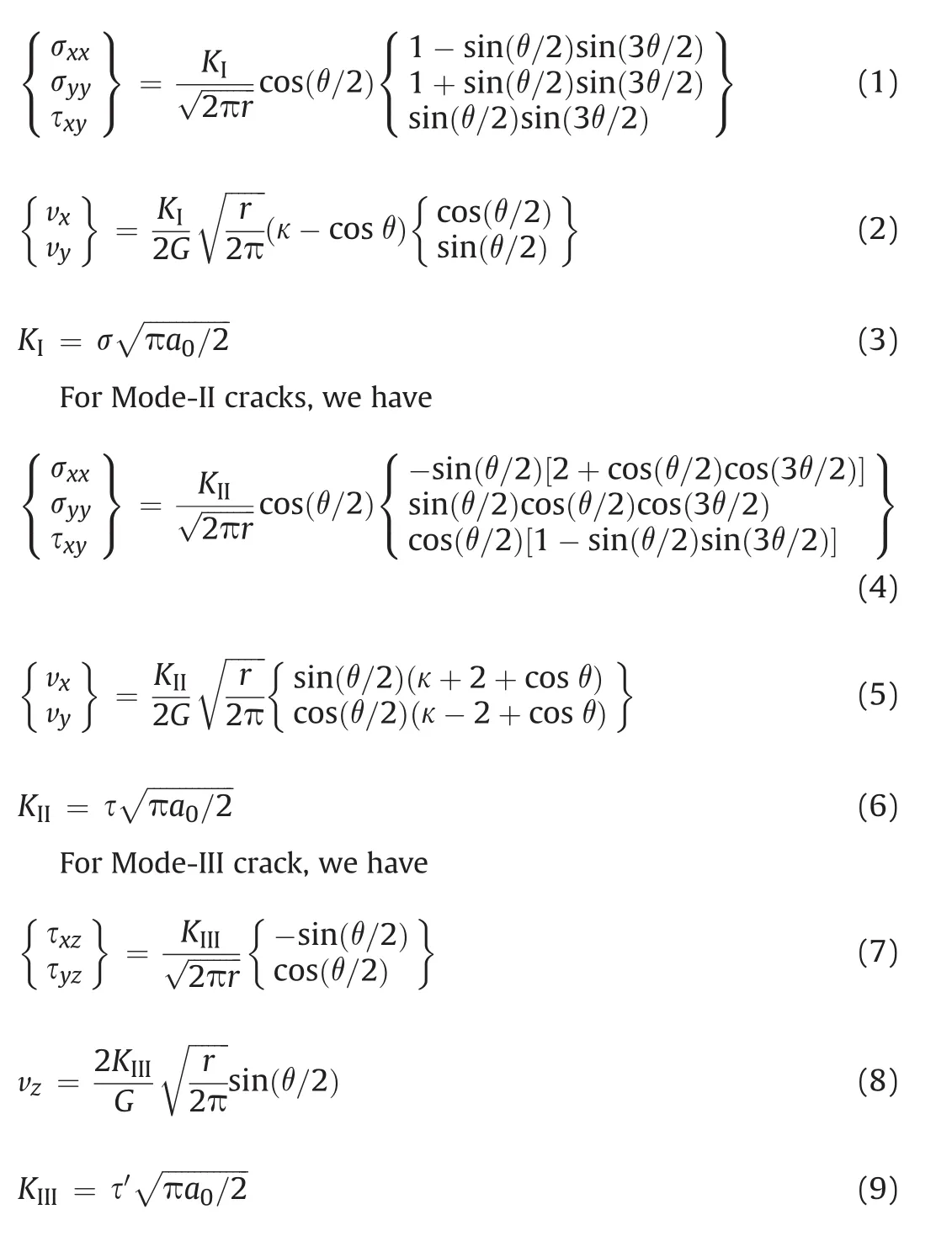
whereris the distance from crack tip;θis the angle from horizontal plane; σ, τ,and τ′are the far-field normal and shear stresses,respectively;a0is the length of the crack;σxx,σyy,and σzzare the stress-components of the local crack-tip stress field;vx,vyandvzare the displacements in thex-,y-andz-direction,respectively;Gis the shear modulus;κ=3-4μholds for plane strain andκ=(3- μ)/(1+μ)for plane stress,andμis the Poisson’sratio,as shown in Fig.2.
According to the time-independent fracture criterion for brittle materials,a crack will suddenly grow when the SIF for a specific mode of loading is equal to the corresponding fracture toughness,i.e.KI=KIC,KII=KIICorKIII=KIIIC.In this concept,fracture toughness represents a material property describing material’s resistance against crack propagation for the corresponding crack modes.As rock material in reality is often subjected to more complex stress conditions than the simple cases of the three basic loading types as shown in Fig.1,the stress and displacement fields are analysed by the superposition method at a linear scale.Such cases are termed as mixed-loading modes and are required to describe the real stress situations.The fracture criterion can be described byf(KI/KIC,KII/KIIC,KIII/KIIIC)=0.For example,Awaji and Sato(1978)and Atkinson et al.(1982)proposed a fracture criterion for a two-dimensional(2D)disc with the central crack as

Fig.1.Three crack opening modes in brittle materials:(a)Mode-I,(b)Mode-II,and(c)Mode-III(Gross and Seelig,2011).

Fig.2.Stress notations for cracks under different loading modes:(a)Mode-I,(b)Mode-II,and(c)Mode-III(Chen,2015).

wherenis a constant to be determined by experiments.
2.2.Time-dependent damage
Typically,the phenomenon of time-dependent deformation in rock material is described as “creep”.Although this effect is mostly examined in medium-to-low strength evaporites(e.g.rock salt,potash),there is certainty that crystalline rocks show time dependent behaviour too.In laboratory testing and in situ observation,this is evidenced that even strong crystalline rocks such as granites show a delayed failure phenomenon under constant load with their long-term strength being lower than measured“instantaneous”strength in the relatively short-term experiments(Dieterich,1972;Schmidtke and Lajtai,1985).Creep in brittle rocks is related to generation of internal microcracks,and their stable growth in length parallel to the maximum compressive load under sustained load leads finally to crack interaction and macroscopic failure through crack coalescence.As indicated by Lajtai and Bielus(1986),the phenomenon of microcrack propagation is sensitive to the applied stress and commonly attributed to subcritical crack growth.The observed macroscopic creep rate is governed by the rate of internal and microscopic damage evolution,which in turn is governed by the speed of subcritical crack growth.This time dependent weakening of crystalline rocks is commonly referred to as“stress corrosion”(Damjanac and Fairhurst,2010)and can be explained by several competing mechanisms such as dissolution,diffusion,ion-exchange,and microplasticity(Potyondy,2007;Brantut et al.,2013).Cruden(1971)statistically re-analysed published creep test data and found a classical creep law of the form:


Fig.3.Time-dependent deformation of brittle rocks at various stress levels(Cruden,1971).
3.Materials and methods
3.1.Specimen preparation
The rock-like material is prepared from rapid-curing gypsum cement.The ingredients are mixed by hand for approximately 30 s before they are cast into aluminium-moulds.Steel shims inside the mould are used to model the open flaws.The mould containers are vibrated to minimise air bubbles inside the specimen.After precuring of the specimens for approximately 4 h,the shims are removed.After 48 h,the specimens are removed from the moulds,labelled and stored under constant temperature and humidity until testing.In order to achieve the homogeneous specimens with isotropic properties,we use pure gypsum without filler or further additives.
3.2.Mechanical and geometrical properties of the specimens
The specimens have a prismatic shape and show good size accuracy as presented in Table 1.The initial damage feature in the specimens is modelled by open flaws with square ends in the rocklike material specimens.The size of the specimens was selected on the basis that influence zone is smaller than 2%of the specimen area.The flaw dip angles inside different groups of specimens are 30°and 60°used to represent initial pre-existing macrocrack orientation.The length of the flaw is 10 mm and the aperture width is 0.6 mm.The group T-60°represents the specimens with double sequential flaws with a dip angle to the loading direction of 60°.Both flaws are in line and the distance between the flaws is 5.7 mm.Each group of specimens is presented in Fig.4.Mechanical properties of the specimens are investigated with standard testing procedures according to German Geotechnical Society(Mutschler,2004; Lepique,2008)on cylindrical specimens which were prepared from gypsum-blocks.

Table 1Geometrical properties of specimens.
The physico-mechanical properties of the rock-like material are obtained from uniaxial compression tests and splitting tensile tests(Brazilian tests).The results are summarised in Table 2.
3.3.Laboratory test procedure
Lifetimes for three groups of specimens are investigated under a constant compressive load in the w+b ag HKB 1000 testing rig-a testing system specifically designed for conducting long-term tests.Fig.5 shows the specimen 30°-#1 when loaded in uniaxial compression in vertical direction.The axial deformation of the middle part of the specimen around the modelled open flaw is measured by linear variable differential transformers(LVDTs).On the opposing sides,they can measure the change in distance between the two rings which are rigidly connected to the specimen below and above the modelled open flaw.
The specimens are loaded to 65%-85%of UCS.The first group of specimens is loaded at an interval of 10%of UCS load increment,whereas the second and third groups are loaded at an interval of 5%of UCS load increment.The maximum load level for the first group is 85%of UCS,whereas the maximum load level for the second and third groups is 75%of UCS.Specimens are subjected to constant compressive load in axial direction until the specimen failure when investigation is interrupted.Time,load and displacement data are automatically recorded and stored on a computer hard disk.
The interval of UCS for the investigation of the specimens is determined on the basis of findings of an extensive laboratory investigation into the identification and qualification of stressinduced brittle fracture damage in rock(Eberhardt et al.,1999).
The crack growth process is recorded by using a video camera featuring 50 fps(frames per second)to observe the cracking mechanisms precisely with sufficient details.The camera is triggered at the same time as the specimen is ready to be exposed to a certain load level.In particular,the tensile-and mixed-mode cracks are determined by visual inspection of crack propagation.Mode-I represents a tensile-mode crack where the crack propagates in its own plane.However,fracture mechanics theory suggests that shear cracks cannot propagate in their own plane.Modes II and III represent shear mode cracks which usually do not propagate in their own plane and develop into wing cracks.The wing cracks propagate in a curved path towards the applied stress directions.The wing cracks are observed in all investigated specimens,for each group and for each load level.Likewise,as the cracks propagate,the length of crack increases and therefore,even at constant load boundary conditions,the specimen ruptures and fails.

Fig.4.(a)Specimen with a single flaw with a 30°dip angle to the loading direction(first group),(b)Specimen with a single flaw with a 60°dip angle to the loading direction(second group),and(c)T-60°specimen with two sequential flaws with a 60°dip angle to the loading direction(third group).

Table 2Physico-mechanical properties of specimens from rock-like material.

Fig.5.Specimen 30°-#1 loaded in uniaxial compression.
4.Results
Irreversible deformation and rock-like material failure occur by progressive material degradation.Microcracks initiate from preexisting macrocracks and grow from a small-scale and coalescent crack to a large-scale wing crack.The modelled open flaw is considered as a stable pre-existing macrocrack.
Long-term deformation during loading with constant axial load is observed and undoubtedly long-term deformation would be also detected in an ideal specimen without flaws.The primary direct effect of the flaw is that the creep deformation rate is enhanced in the presence of the inclined flaw in the centre of the specimen.The secondary effect is crack propagation from the tip of the flaw,occurring after some time of loading which progressively influences deformation behaviour.
In the beginning,the curve(Fig.6)representing axial deformation versus time takes a convex shape.Cracks start to grow in their plane and develop into wing cracks.They initiate in a slow manner simultaneously from the opposite diagonal corners of the pre-existing macrocrack in vertical direction towards the upper and lower boundaries of the specimen,whichever is closer to the tip of the modelled open flaw according to its orientation.At a certain time,the curve of axial deformation versus time exhibits a decrease in axial deformation rate.We name this point“first breaking point”,as shown in Fig.6.It represents the point in which the wing crack propagation starts.As crack growth is now parallel to the loading direction,axial deformation progresses more slowly.At the“second breaking point”,the speed of the axial deformation re-accelerates and the curve of axial deformation versus time takes a concave shape.After the second breaking point,the damage characteristics shift from stable to unstable crack propagation.Shear cracks occur in the presence of the existing wing cracks and the specimen fails in a relatively short period of time-in contrast to the time interval(Ti)when the specimen shows stable deformation behaviour.Tibetween the first and the second breaking points has been determined as shown in Fig.6.
4.1.First group:specimens with a single flaw with 30°dip angle to the loading direction
Wing cracks initiate simultaneously from the opposite diagonal corners of the pre-existing macrocrack in vertical direction towards the upper and lower boundaries of the specimen,whichever is closer to the tip of the modelled open flaw as per its orientation.The crack initiation and growth do not lead to specimen failure,as shown in Fig.7a.The wing cracks are stable and they initiate in a slow manner.At the second breaking point,the shear cracks start simultaneously,propagating from both existing wing cracks.The shear cracks appear to be responsible for the specimen failure and they form in a diagonal direction of the specimen and form in-plane of the modelled open flaw.The specimen is split into two pieces,as shown in Fig.8a,and as follows from Fig.8b,the cut(surface of the exhibited flaw)is clean.Thus,closure of the modelled open flaw does not occur in any specimen of the first group.
Fig.9 shows the results obtained from the laboratory tests,and it demonstrates that all specimens follow the same pattern.It is obvious that lifetimes of specimens subjected to lower axial static compressive loads are longer and the observed axial deformation is larger in comparison with the specimens subjected to higher axial static compressive loads.

Fig.6.Axial deformation vs.time of specimen with a single open flaw with 30°dip angle to the loading direction for the load level of 65%of UCS.

Fig.7.Specimen with a single flaw with 30°dip angle to the loading direction:(a)Wing cracks propagation from modelled open flaw,and(b)Shear cracks propagation from the existing wing cracks.WC:wing crack;SC:shear crack.

Fig.8.(a)Specimen of the first group with wing cracks and shear cracks after failure,and(b)Clean cut of a specimen from the first group after failure.
4.2.Second group:specimens with a single flaw with 60°dip angle to the loading direction
Again,wing cracks initiate simultaneously from the opposite diagonal corners of the modelled open flaw in vertical direction towards the upper and lower boundaries of the specimen,which is closer to the tip of the modelled open flaw according to its orientation as shown in Fig.10a.After the first breaking point,the initiation of the pair of tensile cracks begins.Tensile cracks propagate simultaneously from the opposite diagonal corners of the modelled open flaw in vertical direction towards the upper and lower boundaries of the specimen,which is farther from the tip of the modelled open flaw according to its orientation.Wing cracks and tensile cracks grow in vertical direction due to the joining of microcracks.The pair of tensile cracks is well seen in Fig.10c.At the second breaking point,the connection of awing crack with a tensile crack invertical direction starts either via flaw(see Fig.10d,WC*)or independently(see Fig.10d,WC**).This combination leads to the scenario in which shear cracks arise from wing cracks.The process of initiation of wing and tensile cracks is presented step by step in Fig.10.The shear cracks which develop from wing cracks and are responsible for specimen failure are clearly seen in Fig.11.After failure,the specimens do not disintegrate but stay in one piece as a consequence of high dip angle of the pre-existing macrocracks to the loading direction.The modelled open flaw is some how stitched,thus the split of the specimens,even after failure,is not possible.

Fig.9.Lifetime under static axial compressive load for specimens of the first group.
4.2.1.Comparison of the results for thefirst and second groups of specimens
As discussed previously,axial deformation over time follows the same pattern,and lifetimes of the specimens subjected to lower axial static compressive loads are longer.The observed axial deformations are higher in comparison with the specimens subjected to higher axial static compressive loads.This is confirmed for both groups of examined specimens.Further,the interpretation ofTiof constant axial strain rate and the velocity of axial deformation are discussed.Tiis determined for each specimen by the method described above and the velocity of axial deformation is determined by the coefficient from the linear trend line which is fitted to the laboratory data.Fig.12 shows the lifetime under static axial compressive load of the second group of specimen.

Fig.11.Specimen of the second group after failure with wing cracks,tensile cracks,and shear cracks.
Our findings are presented in Fig.13.It is obvious that the specimens with pre-existing macrocracks and lowerdip angle(30°)to the loading direction show a slightly longerTiwith a constant axial strain rate.On the other hand,the velocity of axial deformation is in this case higher.It is significant for both groups of specimens thatTiis decreasing with the increasing load level.Specimens with lower dip angle(30°)to the loading direction approach to failure at higher deformation rates and all specimens are split into two completely separated pieces as a result of shear crack generation.

Fig.10.Specimen of the second group:(a)A pair of wing cracks,(b)Beginnings of a pair of tensile cracks,(c)Coalescence of wing cracks(WC)and tensile cracks,(d)Specimen just before collapse,and(e)Broken specimen.TC:tensile crack.

Fig.12.Lifetime under static axial compressive load of the second group of specimen.

Fig.13.Time interval(Ti)and velocity vs.load level for specimens of the first group(dip angle 30°)and second group(dip angle 60°).
Axial deformation,tensile and wing crack propagation from the modelled open flaw have not been observed with load levels lower than 50%of UCS.For the time interval observed in this study,the minimum level of constant compressive load to achieve specimen failure within 24 h of loading is 65%of UCS.Undeniably high values of load levels are crucial in the lifetime stability of the specimens.It is obvious that all specimens lose their stability after a certain period of time.The application of a higher load level causes exponential growth of the velocity of axial deformation and exponential reduction ofTiwith a constant deformation rate.
These results demonstrate that pre-existing macrocracks can cause significant damage to the circumference of underground structures.The orientation of macroracks to the external stress field is an important feature which governs the exact lifetime and deformation rate when failure of the rock mass occurs.
4.2.2.Third group:specimens with double flaws with 60°dip angle to the loading direction
As the same in other specimens,initiation of wing cracks starts simultaneously from the opposite diagonal corners from the both modelled open flaws in vertical direction towards the upper and lower boundaries of the specimen,which is closer to the tip of the modelled open flaws according to their orientation,as shown in Fig.14a.Wing cracks propagate independently of the adjacent modelled open flaw.However,the progression of wing cracks in the space between the modelled open flaws is slower than that outside of the pair of modelled open flaws.Wing cracks in between the modelled open flaws are named “inner wing cracks”.At the tips of the modelled open flaws facing each other,the inner wing crack from the left modelled open flaw propagates in an upward vertical direction whereas the inner wing crack from the right modelled open flaw propagates in a downward vertical direction.However,the two wing cracks do not meet but bypass each other.As a result,the modelled open flaws are not connected at any point.

Fig.14.Specimen from the third group:(a)External and internal wing cracks,(b)Beginnings of shear crack,and(c)Broken specimen.EWC:external wing crack;IWC:internal wing crack.

Fig.15.(a)Specimen from the third group in fault condition with presented external wing cracks and shear crack,and(b)Clean cut and interior crack of a specimen from the third group in fault condition.

Fig.16.Slip time of specimen with double flaws with 60°dip angle to the loading direction.
Wing cracks initiating from the left lower corner of the left modelled open flaw in a downward vertical direction towards the bottom of the specimen,and those initiating from the upper corner of the right modelled open flaw propagating in an upward vertical direction are all named “external wing cracks”.
External wing cracks propagate progressively in vertical direction towards the boundary of the specimen.The shear cracks develop directly from the tip of the modelled open flaw and are responsible for specimen failure as shown in Fig.15.
The first part of the shear crack develops from the lower left corner of the modelled left open flaw and the second part develops from the upper corner of the modelled right open flaw.In the meantime,the external wing cracks begin to close and consequently they are not visible with naked eye any longer.At the moment of dominance of the shear cracks,slip happens.On the record,the slip is seen as a movement of the adjacent modelled open flaws which are closer to each other.Movement is small and quick but clearly noticeable.The slip is also presented in Fig.16.It occurs at approximately 16 h into testing.After slip,the specimen is stable again for a certain period of time and loses its stability when the shear cracks connect through the modelled open flaws.Fig.17 shows the results obtained from laboratory tests.It is seen that again,all specimens follow the same pattern as the specimens from the first and the second groups,as shown in Figs.9 and 12,respectively.

Fig.17.Lifetime under static axial compressive load for specimens from the third group.

Fig.18.Time interval and velocity vs.load levels.
In specimens with double flaws,it is observed that-with a higher load level-the constant axial deformation rate is growing exponentially,whereas the duration ofTiis decreasing exponentially.This trend is shown in Fig.18 and is comparable to the behaviour observed in specimens containing only a single flaw.However,the time interval with a constant deformation rate(i.e.the“l(fā)ifetime”)for the third group of specimens is much shorter in comparison with the specimens that have a single flaw.Due to the short durationTiand the high deformation velocity,any self-healing effects in the rock cannot be expected.Moreover,an interior crack develops which connects both modelled open flaws,and it is the result of two combined processes,i.e.the slip(see Fig.16)and the sudden collapse,caused by shear crack propagation.The interior crack is seen in Fig.15b.The point of slip in Fig.16 can be interpreted as the starting point of damage accumulation in the specimen.
4.3.Discussion
Specimens with a single flaw and a dip angle to the loading direction of 30°in general show higher axial deformation at the moment of the specimen failure in comparison with the specimens with a single or double modelled open flaws and a dip angle to the loading direction of 60°at the same load level(Fig.19).Final axial deformation follows the same pattern for the same dip angle to the loading direction.Thus,specimens with lower dip angle to the loading direction withstand higher axial deformation.
It is recognised that for load levels lower than 70%,the lifetime of the specimen with double modelled open flaws is shorter compared to that with a single modelled open flaw.Specimens containing two flaws fail at lower axial deformation at the same load level.The durationTiwith a constant deformation rate directly affects the amount of axial deformation of the specimen but it does nothavean influence on its lifetime.It is obvious that the lifetime of the specimens with a single flaw and dip angles to the loading direction of 30°and 60°at a load level of 75%of UCS is the same,as shown in Fig.13.The durationTiof the specimen from the first group(Fig.13)at a load level of 65%of UCS is much shorter in comparison with the specimen from the second group(Fig.13)at the same load level.The longer durationTiallows a lower final deformation but has no influence on the lifetime.As mentioned above,specimens under the same load fail at the same time.

Fig.19.Maximum deformation at the time of failure for each specimen with single or double flaws for the load levels.
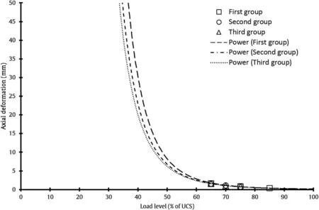
Fig.20.Axial deformation vs.load level.
On the basis of knowing the axial deformation at different loads,the lifetime of specimen could be predicted.Further,the specimens with a dip angle to the loading direction of 60°follows the same pattern independently of the fact whether a single-or double-flaw is presented.It could be concluded that the lifetime could be predicted for any specimen if the dip angle to the loading direction is known.
For all tested setups,the occurrence of the very first cracks does not immediately cause the collapse of the specimens.However,the velocity of crack propagation depends on the load level.It is intuitive that a higher loading level will give faster propagation of cracks and therefore lead to a faster ultimate failure of the specimen.
All groups of specimens show long-term deformation,as shown in Fig.20.From the measured data,it can be concluded that loading levels below approximately 30%or 40%of UCS are leading to infinite deformation without a distinct point of failure.This behaviour which evidences the existence of a long-term strength threshold is in good agreement with the observations of other researches(Eberhardt et al.,1999;Damjanac and Fairhurst,2010).Thus-for the distinct case of the rock-like material used in our study-an infinite lifetime and creep deformation with stationary rate are anticipated.Crack orientation has a minor but noticeable influence on lifetime and bearable axial deformation.A specimen loaded at 50%of UCS containing a pre-existing macrocrack at a dip angle of 30°will have a greater lifetime and the capability to accumulate more(axial)deformation than a specimen with a flaw inclined at 60°,before the specimen fails due to damage accumulation triggered by crack propagation.
5.Conclusions
Prediction of lifetime for rock-like material has been studied for three groups of specimens under axial static compression at various load levels.It has been found that crack propagation for specimens with a single flaw follows the same sequences irrespectively of load level and orientation of macrocrack(flaw)to the loading direction.At first,wing cracks appear and then specimens fail due to shear cracks developing from the existing wing cracks.For specimen with double modelled open flaws,the shear cracks develop directly from the tip of the flaws.For the group of specimens with a single flaw with a 60°dip angle to the loading direction,the tensile cracks are typically representative.A clean cut is observed in the specimens with single and double flaws with 30°and 60°dip angles to the loading direction,respectively.For specimens with double flaws with 60°dip angle to the loading direction,a slip is expected.A slip connects double individual modelled open flaws.The slip time is noticed as a peak characteristic rise in axial deformation at the constant load level.
In this study,it is observed that the relationship of axial deformation versus time follows the same pattern irrespectively of local geometry.On this basis,we plan to develop additional schemes for lifetime prediction for rocks in presence of cracks with a certain dip direction under axial static compressive load.It is shown that specimens subjected to higher load levels have shorter lifetime.Furthermore,lower axial deformation and higher rate of axial deformation are observed in comparison with specimens subjected to lower axial static compressive strength.At all tested load levels,specimens with a single flaw dipping at 30°to the loading direction exhibit higher axial deformation in comparison with specimens with a single flaw dipping at 60°.This is applicable for identifying the lifetime of excavation where the cracks in rocks are induced by an excavation process and a redistribution of an in situ stress field.It is highlighted that lower dip angle to the loading direction represents a favourable alignment and has favourable effect on short and long-term stability of an excavation.For specimens with double flaws dipping at 60°,lifetime as well as axial deformation at the time of failure is further reduced.
Conflicts of interest
The authors wish to confirm that there are no known conflicts of interest associated with this publication and there has been no significant financial support for this work that could have influenced its outcome.
Atkinson C,Smelser RE,Sanchez J.Combined mode fracture via the cracked Brazilian disk.International Journal of Fracture 1982;18(4):279-91.
Awaji H,Sato S.Combined mode fracture toughness measurement by the disk test.Journal of Engineering Materials and Technology 1978;100(2):175-82.
Bieniawski T,Bernede MJ.Suggested methods for determining the uniaxial compressive strength and deformability of rock materials.International Journal of Rock Mechanics and Mining Sciences&Geomechanics Abstracts 1979;16(2):138-40.
Bobet A,Einstein HH.Fracture coalescence in rock-type materials under uniaxial and biaxial compression.International Journal of Rock Mechanics and Mining Sciences 1998;35(7):863-88.
Brantut N,Heap MJ,Meredith PG,Baud P.Time-dependent cracking and brittle creep in crustal rocks:a review.Journal of Structural Geology 2013;52(5):17-43.
Cao RH,Cao P,Lin H,Pu CZ,Ou K.Mechanical behavior of brittle rock-like specimens with pre-existing fissures under uniaxial loading: experimental studies and particle mechanics approach.Rock Mechanics and Rock Engineering 2016;49(3):763-83.
Chen W,Konietzky H.Simulation of heterogeneity,creep,damage and lifetime for loaded brittle rocks.Tectonophysics 2014;633:164-75.
Chen W,Konietzky H,Abbas SM.Numerical simulation of time-independent and dependent fracturing in sandstone.Engineering Geology 2015;193:118-31.
Chen W.Damage characteristics of brittle rocks inside the pre-failure range:numerical simulation and lab testing.PhD Thesis.TU Bergakademie Freiberg;2015.
Cruden DM.The form of the creep law for rock under uniaxial compression.International Journal of Rock Mechanics and Mining Sciences&Geomechanics Abstracts 1971;8(2):105-26.
Damjanac B,Fairhurst C.Evidence for a long-term strength threshold in crystalline rock.Rock Mechanics and Rock Engineering 2010;43(5):513-31.
Dieterich JH.Time-dependent friction in rocks.Journal of Geophysical Research 1972;77(20):3771-81.
Eberhardt E,Stead D,Stimpson B.Quantifying progressive pre-peak brittle fracture damage in rock during uniaxial compression.International Journal of Rock Mechanics&Mining Sciences 1999;36(3):361-80.
Griffith AA.The phenomena of rupture and flow in solids.Philosophical Transactions of the Royal Society of London:Series A 1920;221(2):163-98.
Gross D,Seelig T.Fracture mechanics:with an introduction to micromechanics.Mechanical engineering series.Berlin Heidelberg:Springer-Verlag;2011.
Inglis CE.Stresses in a plate due to the presence of cracks and sharp corners.Transactions of the Institution of Naval Architects 1913;55:219-30.
Irwin GR.Onset of fast crack propagation in high strength steel and aluminium alloys.Washington,D.C.,USA:Naval Research Laboratory;1956.
Irwin GR.Analysis of stresses and strains near the end of a crack.Journal of Applied Mechanics 1957;24:361-4.
Konietzky H,Heftenberger A,Feige M.Life-time prediction for rocks under static compressive and tensile loads:a new simulation approach.Acta Geotechnica 2009;4(1):73-8.
Lajtai ZE,Bielus PL.Stress corrosion cracking of Lac du Bonnet granite in tension and compression.Rock Mechanics and Rock Engineering 1986;19(2):71-87.
Lepique M.Empfehlung Nr.10 des Arbeitskreises 3.3 “Versuchstechnik Fels”der Deutschen Gesellschaft für Geotechnik e.V.:Indirekter Zugversuch an Gesteinsproben-Spaltzugversuch/Indirect tensile test of rock samples-splitting tensile test.Bautechnik 2008;85(9):623-7(in German).
Liu T,Lin B,Yang W,Zou Q,Kong J,Yan F.Cracking process and stress field evolution in specimen containing combined flaw under uniaxial compression.Rock Mechanics and Rock Engineering 2016;49(8):3095-113.
Mutschler T.Neufassung der Empfehlung Nr.1 des Arbeitskreises“Versuchstechnik Fels”der Deutschen Gesellschaft für Geotechnik e.V.:Einaxiale Druckversuche an zylindrischen Gesteinsprüfkürpern[New version of recommendation No.1 of the working group “Experimental Techniques of Rock”of the German Society for Geotechnical Engineering e.V.:“Uniaxial compression tests of cylindrical rock samples”].Bautechnik 2004;81(10):825-34(in German).
Potyondy DO.Simulation stress corrosion with a bonded-particle model for rock.International Journal of Rock Mechanics and Mining Sciences 2007;44(5):677-91.
Schmidtke RH,Lajtai EZ.The long-term strength of Lac du Bonnet granite.International Journal of Rock Mechanics and Mining Sciences&Geomechanics Abstracts 1985;22(6):461-5.Abstract.
Wong LNY,Einstein HH.Fracturing behavior of prismatic specimens containing single flaws.In:Golden Rocks 2006,The 41st U.S.Symposium on Rock Mechanics(USRMS):50 Years of Rock Mechanics-Landmarks and Future Challenges,Colorado;2006.p.1-10.
Wong LNY,Einstein HH.Crack coalescence in Molded gypsum and Carrara marble:Part 1.Macroscopic observations and interpretation.Rock Mechanics and Rock Engineering 2009;42(3):475-511.
Zhou XP,Cheng H,Feng YF.An experimental study of crack coalescence behaviour in rock-like materials containing multiple flaws under uniaxial compression.Rock Mechanics and Rock Engineering 2014;47(6):1961-86.was an Assistant at the University of Ljubljana,Faculty of Natural Sciences and Engineering,with habilitation at the Department of Geotechnology,Mining Engineering and Environment where she taught practical part of subjects in Master and Bachelor programmes.She has published 7 scientific papers,several conference papers,research reports,treatises,and preliminary studies.She has been a supervisor for Master’s theses and translated a book titled Tunnels:guidelines for good occupational health and safety practice in tunnel construction.
 Journal of Rock Mechanics and Geotechnical Engineering2018年1期
- Journal of Rock Mechanics and Geotechnical Engineering的其它文章
- Corrigendum to“Back-analysing rock mass modulus from monitoring data of two tunnels in Sydney,Australia”[J Rock Mech Geotech Eng 5(2017)877-891]
- Effects of lime addition on geotechnical properties of sedimentary soil in Curitiba,Brazil
- KIN SP:A boundary element method based code for single pile kinematic bending in layered soil
- Anisotropy effect on strengths of metamorphic rocks
- Geomechanical characterization of volcanic rocks using empirical systems and data mining techniques
- Influence of loading and heating processes on elastic and geomechanical properties of eclogites and granulites