
Effect of a transverse plasma jet on a shock wave induced by a ramp
2017-12-22 06:23:11HongyuWANGJunLIDiJINHuiDAITianGANYunWU
CHINESE JOURNAL OF AERONAUTICS 2017年6期
Hongyu WANG,Jun LI,Di JIN,Hui DAI,Tian GAN,Yun WU
Effect of a transverse plasma jet on a shock wave induced by a ramp
Hongyu WANG,Jun LI*,Di JIN,Hui DAI,Tian GAN,Yun WU
Flow control; Improved delayed detached eddy simulation(IDDES)method; Plasma synthetic jet; Shock wave/boundary layer interaction; Time resolved schlieren system
We conducted experiments in a wind tunnel with Mach number 2 to explore the evolution of a transverse plasma jet and its modification effect on a shock wave induced by a ramp with an angle of 24°.The transverse plasma jet was created by arc discharge in a small cylindrical cavity with a 2 mm diameter orifice.Three group tests with different actuator arrangements in the spanwise or streamwise direction upstream from the ramp were respectively studied to compare their disturbances to the shock wave.As shown by a time-resolved schlieren system,an unsteady motion of the shock wave by actuation was found:the shock wave was significantly modified by the plasma jet with an upstream motion and a reduced angle.Compared to spanwise actuation,a more intensive impact was obtained with two or three streamwise actuators working together.From shock wave structures,the control effect of the plasma jet on the shock motion basedon a thermal effect,a potential cause of shock modification,was discussed.Furthermore,we performed a numerical simulation by using the Improved Delayed Detached Eddy Simulation(IDDES)method to simulate the evolution of the transverse plasma jet plume produced by two streamwise actuators.The results show that flow structures are similar to those identified in schlieren images.Two streamwise vortices were recognized,which indicates that the higher jet plume is the result of the overlap of two streamwise jets.
1.Introduction
Control of Shock Wave/Boundary-Layer Interaction(SWBLI)which results in boundary layer separation has been widelyinvestigated for its practical implications.The wave drag and friction drag caused by SWBLI are severe and the pressure fluctuations within the unsteady separated region lead to localized fatigue loading and the premature failure of a structure.1–5
Both passive and active control methods for the purpose of diluting the negative impact of SWBLI have been widely studied.6–10One of the representative passive methods is the use of mechanical/micro jet vortex generators.Researchers examined the separation control performance of their passively generated upstream disturbances.11,12Such devices generate an energetic counter-rotating vortex that allows momentum transfer(between the main flow and the boundary layer)thereby altering the characteristics of the incoming boundary layer.However,because the installation position of such devices is relatively fixed,passive methods have limited effectiveness on a flow,and the amplitude of the disturbance may be sensitive to different flow conditions.Therefore,a lot of optimization work has been done to improve the performance of such devices.13–15
In contrast,active control methods such as energy deposition and injection are more flexible in terms of supersonic flow control.Therefore,in recent years,some novel actuators for manipulating supersonic flow such as nanosecond-pulsed Dielectric Barrier Discharge(ns-DBD),16–18Localized Arc Filament Plasma Actuators(LAFPAs),19–21direct-current glow discharge,22–25and Pulsed Plasma Synthetic Jet Actuator(PPSJA)26–30have been put forward.
The control mechanisms for SWBLI using such actuators have been widely discussed,which can be summarized as follows:(A)thermal accumulation effect that weakens the shock wave by using direct arc discharge with a relative high energy31–33;(B)Lorenz-force or electrostatic-force accelerated plasma that adds momentum into the surrounding fluid34–36;and(C)unsteadiness of the boundary layer or shear layer intrigued by disturbance from high-frequency actuation for a forced laminar boundary layer transition or shock wave instability alleviation.37,38,9
In brief,typical SWBLI manipulation methods can be categorized by continuous ones and pulsed ones with a range of frequencies,which enhance flow mixing by adding momentum parallel or normal to the wall or triggering the instability of flow structures such as the boundary layer and the shear layer.Actuation intensity is of importance for flow mixing as the basic problem is to augment momentum to the very nearwall region of the boundary layer.On the other hand,the excitation frequency is essential for the pulsed category,because it may determine the response characteristics of different flow structures.For example,in SWBLI,the pulsation frequency of the separation shock is at least two orders of magnitude lower than that of the energetic eddy in the boundary layer.39–41
The PPSJA is a potential supersonic flow control method for its high instantaneous speed and flexibility.This actuator not only adds momentum to the boundary layer,but also induces additional flow structures such as shock waves and streamwise vortex rings that may interact with the interaction region to suppress separation or decrease the friction drag.Research results from Narayanaswamy et al.42showed that a pulsed plasma synthetic jet could modify the large-scaled motion of the separation shock.The oscillation frequency of the shock wave was forced in the actuator’s frequency,and the thermal effect was considered as the reason for the shock motion.Study by Webb et al.43also indicated that the thermal effect of plasma was the key factor to make the separation shock move upward.Results from Greene et al.44showed that a plasma synthetic jet could reduce the shock-induced boundary layer separation.The separation line upward on a ramp shown by the oil flow technique was pushed downstream by the streamwise vortex created by the jet.Large eddy simulation made by Yang et al.45revealed a reduction of the separation region caused by plasma jets whose function is similar in a mechanical vortex generator.Emerick et al.46studied the oblique shock modi fication induced by a plasma jet,and showed that a maximum flow deflection angle of 5°could be created by the jet at Mach number 1.5,demonstrating its authority to impact on the shock wave.
From above,we can conclude that a plasma synthetic jet may affect greatly on the shock wave or its induced boundary layer separation.It is generally believed that the thermal effect of the plasma jet plays an important role in the shock modification,but how the plasma jet acts on the shock wave has not been studied.This paper mainly focuses on the transverse plasma jet evolution in a supersonic flow and its disturbance effect on the shock wave induced by a ramp using the highspeed schlieren technique.Firstly,the characterization of the plasma jet in quiescent air was brie fly studied.Then,a detailed discussion was made on the effect of the plasma actuators arrangement on the shock wave.Control effectiveness was suggested based on two-dimensional(2D)schlieren images.Furthermore,a numerical simulation by the Improved Delayed Detached Eddy Simulation(IDDES)method was made to give a deep insight into the transverse plasma jet evolution produced by two streamwise actuators.
2.Experimental setup
2.1.Wind tunnel
Experiments were conducted in a 0.05 m×0.05 m supersonic wind tunnel composed of a 2D Laval nozzle and a test section with Ma∞=2.0(Ma∞is the freestream Mach number).The tunnel is supplied with ambient air with a stagnation pressure p0and a stagnation temperature T0of(96.5±0.1)kPa and(298±1)K,respectively.The test section is connected to a vacuum tank with a volume of 120 m3.Stable test time about 30 s can be achieved.Start-up of the wind tunnel is accomplished by using a plug valve at the end of the text section.The nozzle pro file of the wind tunnel was designed by the characteristic line method with a 2.182 mm displacement thickness of the boundary layer at the exit of the nozzle.47Two optical glasses,0.1 m×0.02 m×0.05 m,were installed on both sides of the test section to provide optical access for flow visualization.Plasma jet actuators were installed at the bottom of the test section.Downstream from the actuators there is a small ramp with a 0.03 m width,a 0.008 m height,and an inclined angle of 24°.The schematic diagram of the wind tunnel and the photo of the actuators are shown in Fig.1.The Reynolds number,90 mm away from the leading edge of the ramp,was about 1.57×10⁶.Based on the images captured by a schlieren system,the flow field is uniform except for a compression wave induced by installation,which meetsthe experimental requirement.
2.2.Plasma synthetic jet actuators
Each actuator is composed of a cylindrical cavity made of Te flon and two tungsten electrodes with a diameter of 1 mm.The electrodes are stuck to the side of the cylindrical cavity and the distance between two adjacent ones is 2 mm.The cylindrical cavity was designed with external and internal diameters of(6±0.1)mm and(4±0.1)mm,respectively,and a depth of(8±0.1)mm.The actuators were inserted into a foundation part made of aluminium alloy.Cylindrical ori fices were punched on the top surface of the aluminium alloy part as the exit of the jet with a diameter of 1 mm and a depth of 1 mm.The schematic diagram of the actuators is shown in Fig.2.In the experiments,three sets of discharge channels integrated in the actuators are used.Multiple discharge channels in a series circuit can be broken down simultaneously if adequately high voltage is applied to the actuators.
2.3.Power supply and synchronization control system
The energy for the actuators is supplied by a pulsed highvoltage power supply(KGD-NSPS3U30F2)and a highvoltage DC power supply.48The pulsed high-voltage power supply is mainly used to break down the air between the electrodes,and the DC power supply is used for energy supply with a high-voltage non-inductive 2 μF capacitor.Once the air is broken down by high voltage,the capacitor charged by the DC power supply would discharge when a high-current arc between electrodes is established.Two high-voltage diodes are used in the circuit to prevent damage to the power supply once short circuit occurs.Three sets of discharge channels can be achieved simultaneously.The whole energy could be modulated by adjusting the voltage of the DC power supply.
The discharge process and data acquisition with a CCD camera(PHANTOM V2512)must be synchronized.It is realized by manually triggering an oscilloscope(Tectronix DPO 4104)when a stable flow field is established in the test section.The signal from the oscilloscope triggers a waveform generator and the CCD camera to work simultaneously;meanwhile,the waveform generator drives the high-voltage pulsed power supply to work.Because the CCD camera has an internal storage function,data before and after the trigger point can both be saved,trigger delay doesn’t need to be adjusted to capture images at the beginning of the discharge.The specific synchronization system is shown in Fig.3.A voltage probe(Tectronix P6015A)and a current probe(Tectronix TCP0030A)are respectively used to measure the total electric potential and current in the circuit.
2.4.Time resolved imaging system
A typical Z-type optical system was used in the experiments,which consists of a light source,two concave lens with a 3 m focal length and a 20 mm diameter,optical glasses on both sides of the wind tunnel,and a high-speed CCD camera.The light source is a Xenon lamp(Zolix LSP-x500A)which supplies continuous light source.The CCD camera captures instantaneous images of the flow field.In these tests,the resolution of the CCD camera was set to be 384 pixel×128 pixel,and the exposure time was 1 μs.The corresponding frame rate was set to be 320000 frame/s with the interval shooting time δ=3.125 μs,ensuring that more information of the flow evolution could be acquired.The focal point converged by the concave lens was cut by a knife edge fixed before the camera lens for a proper image contrast.
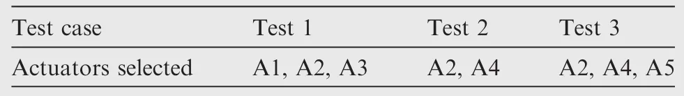
Table 1 Three tests with speci fic actuators.
Three tests were conducted with the actuators in a stream wise or span wise arrangement to study the evolution of the plasma jet and its disturbance to the shock wave.Narayanaswamy et al.42suggested that actuators arranged upstream from the shock wave may exert significant disturbance to the shock wave,so in these tests,all the actuators were arranged at least 30 mm away from the ramp,upstream from the shock wave.The spacing between the center of each actuator was 8 mm,and the identifiers from A1-A5 were given to each actuator,as shown in Fig.4.Specific numbered actuators were selected for each set of the tests,which are listed in Table 1.The distance between the horizontal array of the actuators(A1–A3)and the edge of the ramp(L)was 30 mm.
3.Results and discussion
3.1.Jet characteristics in ambient air
Firstly,the waveform of discharge in Test 1 is given in Fig.5.It is shown that if the discharge channel is establishing,there is a downward trend in the voltage,but a sudden increase in the current occurs and then a single peak is formed.That is because once the air is broken down by high voltage,the resistance value of the whole circuit is decreased.The instantaneous power is acquired by multiplication of the voltage and the current,and the energy of discharge for a single pulse can be calculated by integral of the power curve.It is noted that the total energy supplied to the actuators is determined by the noninductive capacitance,so no matter discharge in quiescent air or in supersonic flow,the energy provided should be almost the same.In the experiments,the calculated total energy of three actuators in quiescent air is 869 mJ and in the supersonic is 966 mJ.Noting that only two actuators were selected for Test 2,we reduce the discharge energy by 633 mJ through adjusting the voltage of the DC power,about two-thirds of the energy in Test 1,to ensure the same penetration height in these three tests.
Schlieren images of the jets produced by three actuators in quiescent air are shown in Fig.6(t is the time).The images are shot with a frame rate of 190000 frame/s,an exposure time of 1 μs,and a shooting interval of 3.7 μs.As depicted in these images,three typical flow structures in the jets can be distinguished as the blast wave,vortex ring,and jet rod.The instantaneous velocity of the leading edge of the vortex ring,as shown in Fig.7,presents obvious oscillation and a tendency to decrease.The average speed(averaged by 30 intervals)is estimated up to 137.8 m/s.It is inferred that the vortex ring plays a dominant role in boundary layer penetration with its initial high instantaneous momentum.The intensity of a jet is gradually weakening with its evolution which indicates rapid energy dissipation of the jet.Because of high energy deposited,the vortex ring at the final stage separated from the jet rod and spread independently.The approximate location of the vortex ring is in the center of the regions between blast waves and the top surface of the actuators,and it is estimated that the propagation velocity of the shock wave is about 2 times higher than that of the jets.Inferred from the intensity of blast shocks and the shape of the jets,the energy in each cavity is not equally distributed,which may be related to the electrode spacing or the distance between the tips of the electrodes and the bottom of the cavity.49
3.2.Characteristics of a transverse plasma jet and its effect on shock
Figs.8,9,10 show the schlieren images acquired in the three tests,which depict the evolution of the jet in a supersonic flow and its disturbance to the shock induced by the ramp.Several typical snapshots are chosen for analyzing the flow phenomena.Figs.8(a),9(a),10(a)show the blast wave produced by abrupt pressure and temperature increases in the process of discharge.It is indicated that the jet produces a considerable instantaneous thrust with its high velocity.The jet breaks down the boundary layer which shows its penetration effect at the initial stage.Then,the gas erupts from each cavity and evolves into a plume seen from Figs.8(b),9(b),10(b),providing momentum to the flow near the wall.Meanwhile,the initial blast wave grows into an oblique shock induced by the transverse jet.
Energetic eddies of different scales could be recognized in the revolution of the jet,which may be because of velocity fluctuation in the jet caused by pressure oscillation in the cavity.Besides,the jet plume close to wall may be subjected to strong shear stress from the high-speed main flow.Figs.8(d),9(d),10(d)show the interaction between the plume and the rampinduced oblique shock wave.The shock wave becomes curved which looks as diffused during the jet passing through.Afterwards,the shock wave moves upstream to be straight with a decreased shock angle,which indicates that the shock becomes weak,as shown in Figs.8(e),9(e),10(e).Finally,as shown in Figs.8(f),9(f),10(h)the shock wave returns to its initial position after the jet has totally passed across the shock wave.
Concrete analysis was made on the evolution of the plasma jet at this part.The jet angle could be de fined as the angle between the top edge of the plume and the bottom wall of the test section.Figs.8(c),9(c),10(c)show the jet angle when the jet reaches at the foot of the shock wave.The jet angles are 8.4°,11.4°,and 14.6°,respectively for each test.Obviously,the jet angle is even bigger when the plume is formed with two or three streamwise actuators in Test 2 and Test 3.The jet angle produced by spanwise actuators is small,which may be because the jets interact weakly with each other.However,if two or three streamwise actuators are used,the jet plume becomes higher,resulting in a more extensive disturbance to the shock,as shown in Fig.10(f),and the displayed diffusion of the shock is more obvious.In addition,a comparison was made on the response of the shock wave to the jet plume in each test.With more actuators in the streamwise direction,the angle of the shock decreased more dramatically.Specifically,Fig.10(b)shows the mixing process of the jets produced by three actuators.The jets blended with each other,enhancing serious turbulence in the boundary layer.It is conductive for a laminar boundary layer to delay separation by a forced transition,and for a turbulent boundary layer to reduce the friction drag.
We find the phenomena of bending and diffusing of the shock wave when the jet plume is passing through.The shock wave returns to its initial position once the plume has completely passed by.It is inferred from the flow structures that there is no separation bubble near the corner of the ramp,or the separation bubble is extremely small so we could not see decomposition of the separation bubble broken down by the plume.However,we see that the interaction zone is transiently occupied by the plume,and deformation of the shock occurs.
The control effectiveness of the plasma jet on the shock wave based on the thermal effect can be described as follows.When the high-temperature jet plume is passing the corner of the ramp,the separation zone if exists will be degraded by the plume with high turbulence and high temperature.The interaction zone is occupied by the plume which leads to a local acoustic velocity increase,reducing the local Mach number.Thus,the sonic line is lifted from the wall,and recombination occurs to the shock wave.The shock wave becomes curved which looks as diffused and eventually stretches far upstream from the ramp with a decreased angle,which is responsible for reducing the wave drag.The description above is similar to the results measured by Particle Image Velocimetry(PIV)in Ref.42,which stated the process of a separation bubble increasing and then decreasing during a jet passing by,and we think that the increase of the separation bubble corresponds to the lifting of the sonic line.
In fact,all the phenomena we have seen are related to the decrease of the local Mach number.The effect of the plasma jet plume on the shock wave can be described by Fig.11.The jet plume uplifts the separation shock,making both the separation and reattachment points attached on the plume,so that the shock wave structure changes significantly.Therefore,we can see the phenomenon of shock wave diffusion.Furthermore,a stronger disturbance will be exerted on the shock wave if the penetration height of the plume increases.
Due to the strong shear stress from the main flow or the pressure oscillation in the cavities,the plume growing along the wall is resolved into several energetic eddies of some scales,shown clearly in Fig.10(f).To some extent,the scales of these energetic eddies in the jet is a little larger than that in the boundary layer.Even so,the frequency of these organized eddies in the jet is still very high,so the shock forced upstream by the jet will not be back soon if the jet is passing through the shock.However,the pulsing frequency of an actuator is limited by its recharging process,so the shock may not be controlled continuously.For these three tests,we performed statistics for the interaction time between the jet plume and the shock which is approximately 127 μs,136 μs,and 156 μs,respectively,which indicates that the interaction time would not be significantly extended even there are multiple streamwise actuators working together.However,what has happened is a better control effect from the actuators.
3.3.Numerical simulation on mixture characteristics of two plasma jets
3.3.1.Physical model and numerical method
The physical process of the simulation can be described as the jets are expelling from the actuator cavities by discharge into supersonic flow.Thus,the calculation area is divided into two parts:the cavities with energy addition and the main flow.
Haack et al.50suggested a model for simulating energy addition into a cavity by adding a heat source term into energy equations.By adjusting a parameter related to heating efficiency,the calculated pressure was in accordance with the measured pressure at the bottom of an actuator’s cavity.In the same way,Jin et al.51simplified the experimental power density acquired from a power waveform through a data fitting method to model the heat source term.Numerical contours are consistent with schlieren images.In this simulation,we adopt Jin’s method to simulate the arc discharge process in the cavities which would simplify the calculation too.A fiveorder data- fitting method is used to simplify the power waveform measured in Test 2,as shown in Fig.12.
The total energy injected into the cavities based on the simplified curve is 633 mJ,which is approximately equivalent to the experimental result.The expression of the simplified power curve is
where p1–p6,μ1and μ2are the fitting parameters.The heating area is a cuboid,occupying 65%of each cavity.By adding a heat source term in the energy equation to simulate the heating process of the arc,the heat source term(de fined as power density˙q)is determined by the total energy E,the energy conversion rate η,the heating time τ,and the heating volume V(x,y,z)as
where x1,x2,y1,y2,z1,z2and τ1determines the volume of the heated area and time.The ICEM software is used for mesh generation.A multi-block structured grid is used,as shown in Fig.13.To improve the mesh quality and calculation efficiency,the geometrical structure of the cavity with a channel is simplified as a cuboid,whose volume is taken the same as that in the experiments.
The scale of the mainstream computing area is 100 mm×50 mm×16 mm,with grid number of 680×300×120.The total grid points are 24 million with dense grids near the actuators.The purpose of the current study is to investigate the interaction between the jet and the boundary layer.Thus,the mesh around them needs to be re fined enough to better resolve the small-scale structures.The inlet flow velocity is 517.6 m/s,and the Reynolds number base on the characteristic length of the flat plate is about 1.57×10⁶in accordance with the experiments.Hence,the height of the first cells to the wall is set to be 10-6m which guarantees y+<1 to meet the requirements of the IDDES model for grid resolution.
The boundary conditions of the calculated case are shown in Fig.13.The fixed walls including the cavities with their channels are set as a no-slip,adiabatic condition.The in flow is a pressure inlet condition,in which the stagnation pressure p0,static pressure ps,total temperature T0,and x-velocity vxare given,as listed in Table 2,the same as those in the experiments.Hence,the corresponding Mach number is 2.0.The exit of the calculation is a pressure outlet pressure condition,which simulates the supersonic flow out of the exit.The top edge of the calculation area is a pressure far- field condition,in which the Mach number,static pressure,and static temperature are given.Both sides of the calculation are periodic boundaries conditions.
Three-dimensional computational fluid dynamics software FLUENT16.1 was used to solve the unsteady compressible Navier-Stokes equations,coupled with the energy equation with a heat source term.The finite-volume method was used to discrete the equation.The IDDES turbulence model was used to capture subtle flow structures.For solving the compressible high-speed flow field with jets,a density-based solver was used.A second-order implicit scheme is used for time accuracy.The three-order Monotonic Upwind Scheme for Conservation Laws(MUSCL)was used for special discretization,and the Advection Upstream Splitting Method(AUSM+)flux scheme was used for the convective fluxes.The pulsationcharacteristics in the boundary layer were generated by air blowing from a slit with a width of 0.5 mm at x=0.01 m.The boundary layer was forced to transition into turbulence.The time step was set to be 10-8s to satisfy the calculation accuracy.20 iterations were calculated to ensure convergence in each calculation time step.
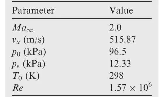
Table 2 Initial conditions.
3.3.2.Simulation results
For a comparison between the simulation and the experiments,the maximum plume height Hmaxin three tests is extracted by the experimental image sequences.The scaled maximum plume height(Hmax/L)over time of the three tests is shown in Fig.14.As can be seen from these curves,the plume height in Test 1 is only 4.3 mm,but in Test 2 and Test 3,it increases rapidly at the beginning with the maximum height reaching up to 8.4 mm and 9.6 mm,respectively.It is also shown that the growth rate of the plume height is gradually reduced over time,and the plume finally maintains a certain height.
In the views of Jin et al.,51based on the method mentioned above,if η=20%,the parameter related to the jet position will agree well with the experimental data measured by the schlieren system.However,because it is a two-dimensional calculation,the results would not reflect the actual situation.On the other hand,Haack et al.50advised that when η=35%,the Navier-Stokes equations in cylindrical coordinates with a heat source were solved,which is more accordant with the reality.By comparison,we set η=35%.The calculated jet height in supersonic flow is compared to that in Test 2,and we find that the data are relatively close,which indicates that the energy injected into the cavity matches well with that in the experiments,as shown in Fig.14.The grid in this paper and a sparse grid of 16 million were used in the calculation,and the jet heights were compared.The result shows little difference,as in Fig.14.Therefore,the grid number in this paper meets the requirement to solve this problem.
The contours of the density gradient magnitude of the transverse plasma jet are given qualitatively in Fig.15.The origin of time was set at the end of discharge.At t=38 μs,as shown in Fig.15(d),the upstream jet was blocked and began to climb onto the downstream one;the jets mixed together into a plume and two peaks are recognized on it with a much higher penetration height.These phenomena in simulation are in good agreement with the schlieren images,as shown in Fig.16.The temperature contours is given in Fig.17.It shows similar jet evolution in accordance with Fig.15.It also shows an extremely high instantaneous temperature in the jet.With the jet expelling out of the cavity,the gas temperature in the cavity decreases.Interacted with the main flow,as shown in Fig.17(b),the transverse jet is entrained forward to the boundary layer.
Q-criterion is used to detect the vortex structures in the jet plume.The simulated vortex structures are shown in Fig.18.The vortex is colored by density.Compared to the main flow,the density of the jet is very low due to high temperature.The low-density area may be dominant for shock attenuation as depicted in Fig.10(e)in that the parameters are changed before and after the shock wave.Meanwhile,a high-density area also exists as the result of a jet-induced shock wave.Fig.18(a)shows that the upstream jet is blocked by the downstream one.Intricate vortex structures are generated by strong interaction.At t=40 μs,the jet separates into two parts with two peaks,and then a couple of large-scale stream wise vortices are recognized,as shown in Fig.18(b)–(d).The upstream stream wise vortex transports on the upper edge of the downstream one,resulting in a much larger penetration height.In other words,the higher plume is the result of the overlap of the two stream wise transverse jets.
4.Conclusions
The control effectiveness of a transverse plasma jet on a shock wave induced by a ramp with an angle of 24°was characterized by the time-resolved schlieren technique.The effects of multiple jets were investigated.The results of three tests with different jet arrangement strategies were compared.A numerical simulation was conducted to give a deep insight into the characteristics of the plume generated by two single jets arranged in the stream wise direction.The results obtained in this paper demonstrate the potential of an actuator for high-speed flow control,especially when multiple actuators are included.
(1)The blast wave interacted with the boundary layer and the evolution of the plasma jet plume present in schlieren images suggest that a transverse plasma jet,produced by discharge into a cavity,enables the boundary layer deeply penetrated.A comparison between the images which depict shock structures and the jet plume height obtained in three tests reveals that multiple actuators arranged in the stream wise direction may create a much higher jet plume,increasing the penetration height and meanwhile exerting a stronger influence on the shock wave.In addition,the characteristics of the evolution of the transverse plasma jet,obtained in the numerical results,are in good agreement with those depicted in the schlieren images,which also con firms this point.The two stream wise vortices recognized in the simulation demonstrate that the higher plume is the result of the overlap of two jets.
(2)The interaction between the plasma jet plume and the shock wave induced by the ramp was also visualized.The shock wave was found to be modified significantly by the plasma jet:the shock wave was forced into an upstream motion with its angle reduced.For Test 3,compared to Test 2 and Test 1,a much more evident modification of the shock wave was obtained.It is inferred that the control effect on the shock wave could be enhanced if multiple stream wise actuators were operated simultaneously in the stream wise direction.However,there is no much change in the interaction time by comparison.
(3)The numerical method adopted in the paper may be a good way to predict the evolution state of a jet in a supersonic flow.It can be used to have an optimization study for improving actuation intensity with multiple actuators.However,the simulation in this paper is limited by jet dynamics,so a further investigation should be made on jet/shock wave interaction to better reveal its mechanism.
Acknowledgements
This study was supported by the National Natural Science Foundation of China(Nos.51522606,51507187,51276197,51407197,and 11472306).
1.Russell A,Zare-Behtash H,Joule KK.Heating flow control methods for high-speed flows.J Electrostat 2016;80(4):34–68.
2.Sriram R,Jagadeesh G.Shock tunnel experiments on control of shock induced large separation bubble using boundary layer bleed.Aerospace Sci Technol 2014;36(7):87–93.
3.Kornilov VI.Current state and prospects of researches on the control of turbulent boundary layer by air blowing.Prog Aerospace Sci 2015;76(7):1–23.
4.Doerffer PP,Bohning R.Shock wave-boundary layer interaction control by wall ventilation.Aerospace Sci Technol 2003;7(3):171–9.
5.Lu F,Li Q,Liu C.Microvortex generators in high-speed flow.Prog Aerospace Sci 2012;53(53):30–45.
6.Souverein LJ,Debieve JF.Effect of air jet vortex generators on a shock wave boundary layer interaction.Exp Fluids 2010;49(5):1053–64.
7.Blinde PL,Humble RA,Oudheusden BWV,Scarano F.Effects of micro-ramps on a shock wave/turbulent boundary layer interaction.Shock Waves 2009;19(6):507–20.
8.Doerffer P,Telega J.Flow control effect on unsteadiness of shock wave induced separation.J Therm Sci 2013;22(6):511–6.
9.Tamba T,Pham HS,Shoda T,Iwakawa A,Sasoh A.Frequency modulation in shock wave-boundary layer interaction by repetitive-pulse laser energy deposition.Phys Fluids 2015;27(9):091704.
10.Azarova OA,Knight DD.Interaction of microwave and laser discharge resulting ‘heat spots” with supersonic combined cylinder bodies.Aerospace Sci Technol 2015;43(6):343–9.
11.Verma SB.Control of shock-wave boundary layer interaction using steady micro-jets.Shock Waves 2013;25(5):535–43.
12.Giepman RHM,Schrijer FFJ,Oudheusden BWV.Flow control of an oblique shock wave reflection with micro-ramp vortex generators:Effects of location and size.Phys Fluids 2013;26(6):1517–31.
13.Zhang Y,Tan H.Control of shock/boundary-layer interaction for hypersonic inlets by highly swept microramps.J Propul Power 2014;31(1):133–43.
14.Zhang B,Zhao Q,Xiang X,Xu J.An improved micro-vortex generator in supersonic flows.J Propul Power 2015;47(12):210–5.
15.Szwaba R.Comparison of the influence of different air-jet vortex generators on the separation region.Aerospace Sci Technol 2011;15(1):45–52.
16.Bisek NJ,Poggie J,Nishihara M,Adamovich I.Hypersonic flow over a cylinder with a nanosecond pulse electrical discharge.J Thermophys Heat Transfer 2014;28(1):18–26.
17.Im S,Do H,Cappelli MA.Dielectric barrier discharge control of a turbulent boundary layer in a supersonic flow.Appl Phys Lett 2010;97(4):041503.
18.Im S,Do H,Cappelli MA.The manipulation of an unstarting supersonic flow by plasma actuator.J Phys D:Appl Phys 2012;45(48):485202.
19.Yan H,Gaitonde D,Shang JS.Numerical investigation of pulsed thermal perturbation in supersonic boundary layer.Reston:AIAA;2007.Report No.:AIAA-2007-3887.
20.Webb N,Clifford C,Samimy M.Control of oblique shock waveboundary layer interactions using plasma actuators.Reston:AIAA;2012.Report No.:AIAA-2012-2810.
21.Webb N,Clifford C,Samimy M.Preliminary results on shock wave/boundary layer interaction control using localized arc filament plasma actuators.Reston:AIAA;2011.Report No.:AIAA-2011-3426.
22.Elias PQ,Chanetz B.Study of the effect of glow discharges near an M=3 bow shock.AIAA J 2007;45(9):2237–45.
23.Shin J,Clemens NT,Raja LL.Schlieren imaging of flow actuation produced by direct-current surface glow discharge in supersonic flows.IEEE Trans Plasma Sci 2008;36(4):1316–7.
24.Shin J,Mahadevan S.Forcing mechanisms in supersonic flow actuation achieved by direct-current surface glow discharge plasma.Aerospace Sci Technol 2011;15(1):18–24.
25.Joussot R,Lago V.Experimental investigation of the properties of a glow discharge used as plasma actuator applied to rare fied supersonic flow control around a flat plate.IEEE Trans Dielectr Electr Insul 2016;23(2):671–82.
26.Narayanaswamy V,Raja LL,Clemens NT.Characterization of a high-frequency pulsed-plasma jet actuator for supersonic flow control.AIAA J 2010;48(2):297–305.
27.Wang L,Xia Z,Luo Z.Three-electrode plasma synthetic jet actuator for high-speed flow control.AIAA J 2014;52(4):879–82.
28.Narayanaswamy V,Shin J,Clemens NT,Raja LL.Investigation of plasma-generated jets for supersonic flow control.Reston:AIAA;2008.Report No.:AIAA-2008-0285.
29.Narayanaswamy V,Clemens NT,Raja LL.Investigation of a pulsed-plasma jet for shock/boundary layer control.Reston:AIAA;2008.Report No.:AIAA-2010-1089.
30.Greene BR,Clemens NT.Effect of pulsed plasma jets on boundary layer recovery downstream of a re flected shock waveboundary layer interaction.Reston:AIAA;2015.Report No.:AIAA-2015-2343.
31.Falempin F,Firsov AA,Yarantsev DA,Goldfeld MA,Timofeev SB,Leonov SB.Plasma control of shock wave con figuration in off-design mode of M=2 inlet.Exp Fluids 2015;56(3):1–10.
32.Bianchi G,Saracoglu BH,Paniagua G,Regert T.Experimental analysis on the effects of DC arc discharges at various flow regimes.Phys Fluids 2015;27(3):036102.
33.Wang J,Li Y,Cheng B,Su C,Song H,Wu Y.Effects of plasma aerodynamic actuation on oblique shock wave in a cold supersonic flow.J Phys D:Appl Phys 2009;42(16):165503–10.
34.Bisek NJ,Rizzetta DP,Poggie J.Plasma control of a turbulent shock boundary-layer interaction.AIAA J 2013;51(8):1789–804.
35.Su C,Li Y,Cheng B,Wang J,Cao J.MHD flow control of oblique shock waves around ramps in low-temperature supersonic flows.Chin J Aeronaut 2010;23(1):22–32.
36.Kimme RL,Hayes JR.Effect of magnetic fields on surface plasma discharges at Mach 5.J Spacecraft Rock 2006;43(6):1340–6.
37.Houpt A,Gordeyev S,Juliano T,Leonov S.Optical measurement of transient plasma impact on corner separation in M=4.5 air flow.Reston:AIAA;2016.Report No.:AIAA-2016-160.
38.Houpt A,Leonov SB.Control of hypersonic BL transition by electrical discharge(feasibility study).Reston:AIAA;2015.Report No.:AIAA-2015-3602.
39.Clemens NT,Narayanaswamy V.Low-frequency unsteadiness of shock wave/turbulent boundary layer interactions.Ann Rev Fluid Mech 2014;46(1):469–92.
40.Gaitonde DV.Progress in shock wave/boundary layer interactions.Prog Aerospace Sci 2015;72(72):80–99.
41.Priebe S,Mart?′n MP.Low-frequency unsteadiness in shock wave–turbulent boundary layer interaction.J Fluid Mech 2012;699(5):1–49.
42.Narayanaswamy V,Raja LL,Clemens NT.Control of unsteadiness of a shock wave/turbulent boundary layer interaction by using a pulsed-plasma-jet actuator.Phys Fluids 2012;24(7):076101.
43.Webb N,Clifford C,Samimy M.Control of oblique shock wave/boundary layer interactions using plasma actuators.Exp Fluids 2013;54(6):1–13.
44.Greene BR,Clemens NT,Magari P,Micka D.Control of mean separation in shock boundary layer interaction using pulsed plasma jets.Shock Waves 2015;25(5):495–505.
45.Yang G,Yao YF,Fang J,Gan T,Li Q,Lu LP.Large-eddy simulation of shock-wave/turbulent boundary layer interaction with and without Spark-Jet control.Chin J Aeronaut 2016;29(3):617–29.
46.Emerick T,Ali MY,Foster C,Alvi FS,Popkin S.SparkJet characterizations in quiescent and supersonic flow fields.Exp Fluids 2014;55(12):1–21.
47.Chang W.Design and development of a rectangular supersonic wind tunnel facility for the study of shock/boundary layer interactions[dissertation].Champaign:University of Illinois at Urbana-Champaign;2011.
48.Zong HH,Cui W,Wu Y,Zhang ZB.In fluence of capacitor energy on performance of a three-electrode plasma synthetic jet actuator.Sensors Actuat A:Phys 2015;222:114–21.
49.Zhang ZB,Wu Y.In fluence of the discharge location on the performance of three-electrode plasma synthetic jet actuator.Sensors Actuat A:Phys 2015;235:71–9.
50.Haack SJ,Taylor T,Emhoff J,Cybyk B.Development of an analytical SparkJet model.Reston:AIAA;2010.Report No.:AIAA-2010-4979.
51.Jin D,Cui W,Li Y,Li F.Characteristics of pulsed plasma synthetic jet and its control effect on supersonic flow.Chin J Aeronaut 2015;28(1):66–76.
Aeronautics and Astronautics Engineering College,Air Force Engineering University,Xi’an 710038,China
2 November 2016;revised 22 January 2017;accepted 5 March 2017
Available online 14 October 2017
?2017 Production and hosting by Elsevier Ltd.on behalf of Chinese Society of Aeronautics and Astronautics.This is an open access article under the CC BY-NC-ND license(http://creativecommons.org/licenses/by-nc-nd/4.0/).
*Corresponding author.
E-mail address:apsl87324@163.com(J.LI).
Peer review under responsibility of Editorial Committee of CJA.
 CHINESE JOURNAL OF AERONAUTICS2017年6期
- CHINESE JOURNAL OF AERONAUTICS的其它文章
- Hybrid task priority-based motion control of a redundant free- floating space robot
- An optimal method of posture adjustment in aircraft fuselage joining assembly with engineering constraints
- Effects of pore structure and distribution on strength of porous Cu-Sn-Ti alumina composites
- Three-dimensional adaptive finite-time guidance law for intercepting maneuvering targets
- Helicopter blades running elevation measurement using omnidirectional vision
- Evasion and pursuit guidance law against defended target