
Effects of axial gap and nozzle distribution on aerodynamic forces of a supersonic partial-admission turbine
2017-12-22 06:23:06JinpengJIANGJiwenLIGuobioCAIJueWANGQiynLIN
CHINESE JOURNAL OF AERONAUTICS 2017年6期
Jinpeng JIANG,Jiwen LI,Guobio CAI,Jue WANG,Qiyn LIN
aSchool of Astronautics,Beihang University,Beijing 100083,China
bSystem Engineering Division,China Academy of Launch Vehicle Technology,Beijing 100076,China
cBeijing Aerospace Propulsion Institute,Beijing 100076,China
Effects of axial gap and nozzle distribution on aerodynamic forces of a supersonic partial-admission turbine
Jinpeng JIANGa,Jiawen LIa,Guobiao CAIa,Jue WANGb,*,Qiyan LINc
aSchool of Astronautics,Beihang University,Beijing 100083,China
bSystem Engineering Division,China Academy of Launch Vehicle Technology,Beijing 100076,China
cBeijing Aerospace Propulsion Institute,Beijing 100076,China
Aerodynamic force; Axial gap; Computational fluid dynamics(CFD); Nozzle distribution; Partial admission; Turbine
The turbine in an LH2/LOX rocket engine is designed as a two-stage supersonic partialadmission turbine.Three-dimensional steady and unsteady simulations were conducted to analyze turbine performance and aerodynamic forces on rotor blades.Different con figurations were employed to investigate the effects of the axial gap and nozzle distribution on the predicted performance and aerodynamic forces.Rotor blades experience unsteady aerodynamic forces because of the partial admission.Aerodynamic forces show periodicity in the admission region,and are close to zero after leaving the admission region.The unsteady forces in frequency domain indicate that components exist in a wide frequency region,and the admission passing frequency is dominant.Those multiples of the rotational frequency which are multiples of the nozzle number in a fulladmission turbine are notable components.Results show that the turbine efficiency decreases as the axial gap between nozzles and the 1st stage rotor(rotor 1)increases.Fluctuation of the circumferential aerodynamic force on rotor 1 blades decreases with the axial gap increasing.The turbine efficiency decreases as the circumferential spacing between nozzles increases.Fluctuations of the circumferential and axial aerodynamic forces increase as the circumferential spacing increases.As for the non-equidistant nozzle distribution,it produces similar turbine performance and amplitude frequency characteristics of forces to those of the normal con figuration,when the mean spacing is equal to that of the normal case.
1.Introduction
Supersonic turbines with partial admission are sometimes employed in rocket engines to avoid an extremely low blade height which would result in large secondary losses such as the tip leakage loss.In addition,partial admission con figurations are commonly applied to control the power output and get higher efficiency in the control stages of power plants and industrial steam turbines.However,additional forms of loss exist in partial admission compared with full-admission turbines,such as the mixing loss generated in the interface regions between the low-energy dead flow and the high-energy through flow,which significantly influences the efficiency.1Furthermore,circumferential non-uniformity is increased due to partial admission.The flow in a turbomachine is highly unsteady because of the interaction between adjacent rows due to the effects of wakes.2,3In a partial-admission turbine,rotor blades periodically pass through flowing regions as well as regions of no flow,inducing strong flow-exciting forces besides vane wakes,which may result in high cycle fatigue.4Rotor blade cracks once occurred in turbopump tests for some liquid rocket engines designed with a partial-admission turbine,and the failure is believed to be caused by exciting forces.It is certainly necessary to investigate the unsteady flow and aerodynamic forces in partial-admission turbines.
Experimental investigations and theory analysis of partial admission have been conducted by several researchers.5–9Numerical simulation has also been a powerful approach widely used by researchers.Full 360°Computational Fluid Dynamics(CFD)models and 3-Dimensional(3D)transient simulations are usually required,and sometimes multistage simulation is needed,which all make numerical investigations with high computational costs.102-Dimensional(2D)1,11and quasi-3D12simulations were usually conducted in the past.With the development of CFD and the improvement of computers,3D transient numerical simulations for investigations of partial admission have been widely conducted.Effects of the axial gap between the first-stage stator and rotor and multiblocking on the performance of partial-admission turbines were numerically studied by Hushmandi and Fransson.13They illustrated that reducing the axial gap produced a better efficiency at the first stage,but the overall efficiency at the second stage was decreased.Numerical simulations were conducted for a steam turbine with different degrees of partial admission by Qu et al.14,and they pointed out that the unsteady computational result was more accurate to analyze the flow of the control stage.Newton et al.15investigated the sources of loss in a turbine with both full and partial admission numerically,and evaluated the distribution of loss with entropy production.From these previous investigations about partial admission,we can see that steam turbines has usually been studied and the turbine aerodynamic performance has mostly been focused on.However,unsteady forces on rotor blades for a rocket engine turbine have been investigated by relatively few studies,especially a turbine with partial admission.J?cker et al.16numerically studied the aerodynamic excitation mechanisms due to the unsteady stator-rotor interaction in a supersonic turbine for a rocket engine turbopump.Hudson et al.17experimentally measured and numerically simulated the surface pressure on a rocket engine turbine blade.Tokuyama et al.18conducted numerical simulation for a partial-admission turbine used for a rocket engine.The blade scaling procedure was adopted,which resulted in a simulation with one third of full passages.The unsteady aerodynamic force was analyzed.They showed that unsteady force components appeared in wide frequencies.Using a genetic algorithm,the partial admission of a supersonic turbine was optimized by Tog and Tousi.19
The turbine in the current study is used for an expander cycle LH2/LOX rocket engine.It is a two-stage supersonic turbine with partial admission.A first-stage rotor blade cracked in a test.Besides processing defects,the excitation produced by the partial admission con figuration and supersonic nozzles was considered to result in the failure.Therefore,the unsteady flow in a full-annulus turbine was numerically investigated in this paper to study the unsteady aerodynamic forces.Furthermore,effects of the axial gap and nozzle distribution on the turbine performance and aerodynamic forces were studied,in order to search for a possible method to reduce the excitation.Con figurations with different equal circumferential spacings between nozzles and unequal circumferential spacings were analyzed to study the effect of the nozzle distribution on the turbine performance and unsteady forces on rotor blades.Con figurations with various axial gaps between nozzles and the firststage rotor were analyzed to investigate the in fluence of the axial gap on the turbine performance and aerodynamic forces.
2.Computational procedures
2.1.Fundamental equation
Reynolds time-averaged Navier-Stokes equations are solved by commercial CFD software of ANSYS-CFX.The general form of governing equations for the compressible viscous unsteady flow in a Cartesian coordinate is expressed as follows:
where ρ is density,φ is the general variable for different equations,t is time,U is velocity,Cφis the general diffusion coef ficient,and Sφis the general source term.Conservation equations for mass,momentum,and energy can be obtained by setting φ to 1,u,v,w,and h,where u,v,w are velocity components,and h is enthalpy.Turbulence models can be obtained when setting φ to turbulence kinetic energy k and turbulent frequency ω.The ideal gas equation of state is adopted for enclosure.
The k-ω based Shear Stress Transport(SST)turbulence model was employed in this study,since it can give highly accurate predictions of the onset and the amount of flow separation under adverse pressure gradients.20–22The SST model combines the advantages of the k-ω model in the near-wall region and the k-ε model in the bulk domain,and accounts for the transport of the turbulent shear stress.The proper transport behavior can be obtained by a limit to the formulation of the eddy-viscosity as:
where a1is equal to 5/9,S is an invariant measure of the strain rate,and F2is a blending function expressed as:
where β′=0.09,y is the distance to the nearest wall,and ν is the kinematic viscosity.
The governing equations were solved using the Finite Volume Method(FVM).The upwind schemes were employed to discrete advection terms,which gave results that agreed well with test results.The second-order implicit schemes were adopted for temporal discretization.
2.2.Computational model and boundary condition
The turbine studied in this paper is a two-stage supersonic turbine with partial admission,and consists of 4 nozzles,56 blades for the 1st stage rotor(rotor 1),28 vanes for the 2nd-stage stator(stator 2),and 58 blades for the 2nd-stage rotor(rotor 2).The rotational speed of rotors at the design point is 42431 r/min.Nozzle and blade pro files are shown in Fig.1,and the CAD(Computer Aided Design)model is shown in Fig.2.
The 3D full-annulus model was taken in simulations.Structural grids for nozzles were generated by Gambit.Computational grids for the 1st rotor and 2nd stator and rotor passages were generated by the IGG/Autogrid software package.Structured grid systems were created in the computational domain with O-type grids near the blade surfaces and H-type grids in the other regions.A grid-dependency check was conducted by simulating the steady flow of the normal con figuration with different grid sizes.The grid size was determined to ensure that the total-to-total isentropic efficiency was stable above that size.The total number of grid nodes was approximately 4500000.
Cases for different axial gaps include a small gap con figuration(20%of the 1st blade axial chord),a normal gap con figuration(32%of the 1st blade axial chord),and a large gap con figuration(46%of the 1st blade axial chord).Table 1 lists the axial gap sizes for the three cases,where bris the 1st blade axial chord length at midspan.Fig.3 shows the considered computational con figurations focused on the axial gap.The axial gap was changed by shifting a nozzle axially.The domain behind the nozzle was elongated or shortened correspondingly,while the rotor domain stayed the same.By doing so,the axial distances between the nozzle-rotor interface and the blade leading edge were the same for all computational con figurations.However,the distances between the nozzle outlet and the interface were different.
Fig.4 is a sketch showing the nozzle distribution,in which nozzles are numbered from 1 to 4 along the direction of rotor rotating,and central angles α1, α2,and α3are used to present the circumferential spacings between nozzles.The circumferential distribution of turbine nozzles was changed by rotating nozzles around the axis.Four con figurations with differentuniform circumferential spacings and a case with non-uniform circumferential spacings were studied.The circumferential spacing sizes for different cases are summarized in Table 2.When the circumferential spacing is 27.5°,the nozzle outlet edges overlap.
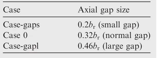
Table 1 Cases with different axial gaps.
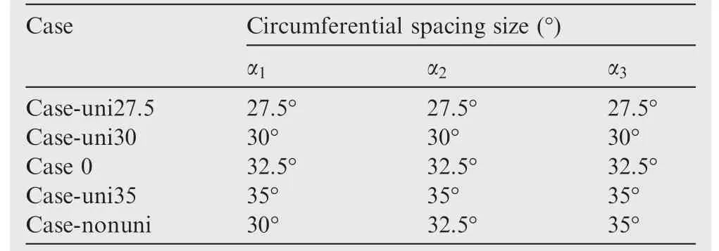
Table 2 Cases with different circumferential spacings.
The working gas in the turbine is hydrogen-rich gas.The specific heat capacity at constant pressure is 8254 J/(kg·K),and the specific heat ratio is 1.3666.The total pressure 3.061 MPa and total temperature 834 K were specified at the inlet.The flow direction was normal to the boundary,and a 5%turbulent intensity was set.Static pressure was imposed at the outlet,which was 0.45 MPa.The mixing plane method was applied for interfaces between the stator and rotor in steady simulations,while the sliding mesh technology was used in unsteady simulations,and steady simulation results were used as initial values for unsteady simulations.No-slip and adiabatic conditions were enforced along all the solid surfaces.100 time steps were set in a nozzle-passing period which was de fined as the period of time required for one blade to pass one nozzle.The convergence criteria for the root mean square residual was set to 1×10-5.20 iterations were performed for each time step to ensure a convergence.
3.Results and discussion
3.1.Flow field analysis
Steady and unsteady simulation results for the designed geometry are analyzed in this section.
Simulation results of mass flow rate(m˙)and turbine efficiency(ηT)are compared with test results in Table 3,and the absolute deviation(Da)and relative deviation(Dr)are given.Test results were obtained from the firing tests for the LH2/LOX rocket engine.The measurement accuracy of mass flow was 0.5%.Predicted errors for mass flow rate and the turbine efficiency are both lower than 1.5%.It reveals that the simulation results are in good agreement with the test results.
A contour plot of the Mach number at midspan is shown in Fig.5.A circumferential non-uniform distribution is produced due to the partial admission con figuration.Flow at the nozzle exit is supersonic,and the Mach number in most of the area is between 1 and 1.7.A rapid flow acceleration occurs around thenozzle exit corner due to the expansion of the working gas,and the maximum Mach number exceeds 2.The acceleration flow is hindered by the next nozzle’s exit flow which is affected in turn by the acceleration flow from the previous nozzle.The high-Mach number region is larger at the No.4 nozzle exit corner leaving the admission area since not being affected by other nozzle exit flow.
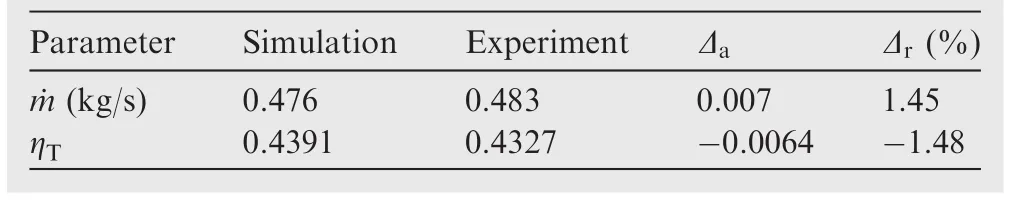
Table 3 Comparison of turbine specific work and efficiency.
The static pressure contours at midspan is shown in Fig.6.Low pressure occurs at the nozzle exit corner due to the expansion of the working gas.Fig.7 shows the circumferential pressure distributions at four positions between stages,and the pressure p is normalized by the inlet total pressure p0,in.The circumferential pressure downstream from rotor 2 is weak,which is close to the outlet pressure and hardly affected by upstream flow.The other pressure distributions have strong circumferential variations due to the partial admission.The pressure distributions show obvious periodicity in the admission area,corresponding to the four nozzles.Pressure is close to the outlet pressure in the non-admission region.Pressure around the region leaving the admission area seems to be lower than that in the region entering the admission area,because the supersonic gas expands and accelerates at the nozzle outlet corners.The pressure distribution between a nozzle and rotor 1 is the most complex.Many local pressure peaks are caused due to the interaction between the supersonic flow and rotor 1 blades.Strong pressure decreasing regions between a nozzle and rotor 1 occur between nozzles,because of the expansion of the supersonic gas at the nozzle exit corners.A larger area of low pressure appears behind the No.4 nozzle.As can be seen,four pressure peaks exist at positions between rotor 1 and stator 2 and between stator 2 and rotor 2,which result from the four nozzles.Pressure distributions at the admission area seem to be approximated by a sine wave.Slight fluctuations around the main wave can also be seen due to the influence of upstream wakes.
Aerodynamic forces on a rotor blade are calculated as follows:
where Ftand Fzare the circumferential and axial forces,respectively,Fviscorepresents the viscous force on the blade,ntand nzare the circumferential and axial unite vectors,respectively,andRspds represents the surface integral of static pressure on the rotor blade.
The unsteady aerodynamic forces(F)on a rotor 1 blade in time domain are plotted in Fig.8.Time was normalized by the rotational period(T),and one cycle is shown.The aerodynamic forces are presented corresponding to the circumferential locations.Both circumferential and axial forces show characteristic due to partial admission.In the admission area,the unsteady forces show great fluctuations because of the nonuniform upstream flow from the nozzles,and periodicity can be seen from the figure.Force peaks occur between nozzle outlets and at the corner of the No.4 nozzle,where a large pressure difference between the pressure side and the suction side occurs.After leaving the admission area,forces on the rotor blade in both directions are close to zero.The circumferential forces are mostly positive(along the rotating direction).There are unusual fluctuations when the blade enters and leaves the admission area.Negative forces are produced around the region entering the admission area.This can be expected,because the suction side enters the high-pressure region ahead of the pressure.For a similar reason,a small positive force peak occurs when leaving the admission area.The axial forces are mostly negative(opposite to the axial flow direction).
Fig.9 shows the results of Fast Fourier Transformation(FFT)analysis of the unsteady aerodynamic forces on the rotor 1 blade.Many frequency components exist in a wide region,which is a characteristic of a partial-admission turbine.The 1st harmonics of the rotational frequency means the admission passing frequency.The 11 multiples of the rotational frequency approximately correspond to the nozzle number in a full-admission turbine.As can be seen,the 1st harmonics is a dominating component in both directions.This can be identified in the regular circumferential distribution of the unsteady force due to the admission as shown in Fig.8.The 1st harmonics for the circumferential force is an absolutely dominating component,while it is relatively weak for the axial force in comparison with the circumferential force.The 11,10,and 12 multiples of the rotational frequency are remarkable,while the 22,21,and 23 multiples of the rotational frequency are notable.As we can see,multiples of 11 multiples components and components adjacent to them are outstanding.However,components over 30 multiples of the rotational frequency are weak.
The unsteady aerodynamic forces on a rotor 2 blade in time domain are shown in Fig.10.Both circumferential and axial forces are also strongly affected by partial admission,just like those on a rotor 1 blade.In the admission area,the forces are mostly positive,and show remarkable periodicity.After the blade leaves the admission area,both forces are close to zero.There are unusual fluctuations for the circumferential force when the blade enters and leaves the admission area.Negative forces are produced around the region entering the admission area,and a small negative force peak occurs when leaving the admission area.
Fig.11 shows the results of FFT analysis of the unsteady aerodynamic forces on the rotor 2 blade.Components over 15 multiples of the rotational frequency are negligible.The frequency range is much narrower compared to that of rotor 1.The 1st harmonic is dominant in both forces.The 11,10,and 12 multiples of the rotational frequency are notable,just like those on a rotor 1 blade.The 2nd harmonic is more significant than 11 multiples component compared to the force on a rotor 1 blade.
Forces on a rotor 2 blade are much lower than forces on a rotor 1 blade,because the pressure in rotor 2 is much lower than that in rotor 1.Thus,aerodynamic forces on a rotor 1 blade are concerned in the following analysis.
3.2.Effects of axial gap
Steady simulations were conducted for cases with different axial gaps,and turbine performances are listed in Table 4.The differences of turbine efficiency from that of Case 0(ΔηT)were calculated,and were expressed as percentages of the normal gap case efficiency.As can be seen,the turbine efficiency decreases as the axial gap increases.This is due to the increase of wake mixing loss between the nozzle exit corners and leading edges of rotors as the axial gap increases.
Fig.12 shows the contours of static entropy(s)on the nozzle-rotor interface plane for con figurations with different axial gaps.As the axial gap increases,the entropy between nozzles decreases.However,the main flow is affected and the entropy downstream from the nozzle outlet increases.In addition,entropy near the inner end wall in the admission region increases when the axial gap increases.As can also be seen in Fig.13 which shows the contours of total pressure(pt)on the nozzle-rotor interface plane,as the axial gap increases,the total pressure between nozzles increases,but the total pressure downstream from the nozzle outlet decreases.By comparing the contours in Figs.12 and 13,it can be seen that increasing the axial gap declined the wake strength and increased the uniformity of flow.However,increasing the axial gap increased the mixing of the wake and the main flow,and losses could be expected to increase.
Histories of the circumferential force on a rotor 1 blade for cases with different axial gaps are plotted in Fig.14.It can be seen that as the axial gap increases,the force peak decreases and the valley increases in the admission area.The fluctuation range of the aerodynamic force apparently reduces,while the mean force barely changes.
Results of FFT analysis of the unsteady circumferential force on a rotor 1 blade for cases with different axial gaps are compared in Fig.15.As can be seen,the amplitudes for main frequencies decrease as the axial gap increases.The amplitude for 1st harmonics slightly decreases,while those for 11,10,22,and 21 multiples of the rotational frequency significantly reduce.It indicates that high-order frequency components are more affected by the axial gap.
Fig.16 shows histories of the axial force on a rotor 1 blade for con figurations with different axial gaps.Major force valleys show little difference among different con figurations.The con figuration with a small axial gap generates a relatively larger minor force valley in the admission area.Generally,the axial force is slightly influenced by the axial gap.
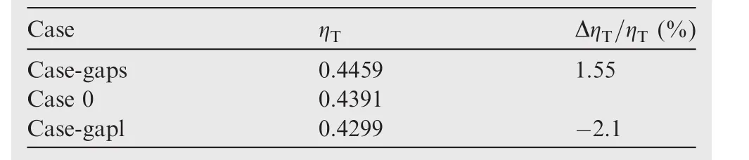
Table 4 Turbine performances for different axial gaps.
Results of FFT analysis of the unsteady axial force on a rotor 1 blade for cases with different axial gaps are plotted in Fig.17.When the axial gap increases,the interaction between nozzles and rotor blades weakens.Minor force valleys decrease and flatten just as shown in Fig.16,and thus highorder frequency components decrease.As can be seen in Fig.17,over the 12 multiples of the rotational frequency,amplitudes decrease when the axial gap increases.Considering that axial forces were slightly affected by the axial gap,when high-order frequency components strengthened,low-order frequency components relatively weakened.It shows that the amplitudes of main low-order frequency components(1st harmonic,11 and 10 multiples of the rotational frequency)increase as the axial gap increases.
In general,increasing the axial gap helps to reduce the unsteady aerodynamic forces,while the turbine efficiency would be sacrificed to some extent.
3.3.Effects of nozzle distribution

Table 5 Turbine performances for different circumferential spacings.
Steady simulations were conducted for con figurations with different nozzle distributions,and turbine performances are compared in Table 5.As can be seen,the turbine efficiency decreases as the circumferential spacing increases.It can be concluded that increasing the circumferential spacing tends to decrease the turbine efficiency,although the reduction is relatively small.This can result from the declining uniformity and the increasing mixing loss between nozzles as the circumferential spacing increases.The con figuration with a non-equidistant nozzle distribution has similar performance to that of the normal case.It’s probably because the former has the same average circumferential spacing as that of the latter.
Fig.18 shows the contours of static entropy on the nozzlerotor interface plane for con figurations with different circumferential spacings.As the circumferential spacing increases,the entropy between nozzles increases and the width increases corresponding to the circumferential spacing.That indicates that both the wake strength and width increase when the circumferential spacing increases.In addition,entropy near the inner end wall in the admission region increases with the circumferential spacing increasing.
Fig.19 shows the contours of total pressure on the nozzlerotor interface plane.As the circumferential spacing increases,the total pressure between nozzles decreases.When the circumferential spacing increases,it becomes difficult for the wake to recover to the main flow.By comparing the contours in Figs.18 and 19,it can be concluded that increasing the circumferential spacing increases the wake strength and decreases the uniformity of flow.
Histories of the circumferential force on a rotor 1 blade for cases with different circumferential spacings are plotted in Fig.20.It can be seen that as the circumferential spacing increases,the force peak slightly increases and the valley significantly reduces in the admission area,except for the No.4 nozzle.The circumferential spacing has little influence on the force peak and valley downstream from the No.4 nozzle.As a result,the amplitude of the circumferential aerodynamic force in the admission region increases,while the mean force slightly decreases.Apparently,the decreasing uniformity between nozzle outlets increases the pressure difference,and thus results in circumferential force peaks increasing.However, flow at the corner of the No.4 nozzle is not affected by the circumferential spacing,and thus the 4th force peak changes little.As for the con figuration with a non-equidistant nozzle distribution,the force peak and valley are equal to those in cases with responding spacing.Downstream from nozzles leaving the admission area,the force peak and valley are almost the same for con figurations with different spacings.
Fig.21 shows the results of FFT analysis of the unsteady circumferential force on a rotor 1 blade for cases with different circumferential spacings.The 1st harmonic is dominant in all cases.However,the main frequency components vary due to different circumferential spacings. Main frequency components for the con figuration with a 27.5°spacing are approximately multiples of the 13 multiples of the rotational frequency,those for the 30°spacing case are approximately multiples of 12 multiples of the rotational frequency,and those for the 35°spacing case are approximately multiples of 10 multiples of the rotational frequency.The con figuration with unequal spacings has similar amplitude-frequency characteristics to those of the normal case.The amplitude of the 1st harmonic slightly varies,while the amplitudes of main high-order frequency components apparently increase as the circumferential spacing increases.
Histories of the axial aerodynamic force on a rotor 1 blade for con figurations with different circumferential spacings are shown in Fig.22.The force peaks in the admission area increase as the circumferential spacing rises,while the force valley value slightly decreases.Similarly,the force peak and valley downstream from the No.4 nozzle are hardly affected.It reveals that increasing the circumferential spacing could result in increasing of the fluctuation range of the axial aerodynamic force.
Results of FFT analysis of the unsteady axial force on a rotor 1 blade for con figurations with different circumferential spacings are plotted in Fig.23.The amplitude-frequency characteristics of the axial force are influenced by the circumferential spacing in a way that the circumferential force is affected.The amplitude of the 1st harmonic decreases,while the amplitudes of main high-order frequency components increase as the circumferential spacing increases.
Generally,increasing the circumferential spacing between nozzles could reduce the turbine efficiency and increase the fluctuation range of aerodynamic forces.It is better to use a circumferential spacing as small as possible when designing nozzles for a partial-admission turbine.
4.Conclusions
3D steady and unsteady flow simulations of a two-stage supersonic partial-admission turbine have been conducted for different con figurations,to investigate effects of the axial gap and circumferential spacing on the predicted aerodynamic performance and forces.Results show that:
(1)A strong circumferential pressure distribution is created by the partial admission.Pressure distributions show obvious periodicity in the admission region,corresponding to the nozzle number.The pressure distribution between nozzles and rotor 1 is especially complex.
(2)Rotor blades experience unsteady aerodynamic forces due to the partial admission.The circumferential force fluctuates when the blade enters and leaves the admission region.Aerodynamic forces show periodic variations due to nozzle exit flow in the admission area,and are close to zero after leaving the admission region.
(3)Unsteady force components on a rotor 1 blade appear in a wide frequency region,and the admission passing frequency which is also the rotational frequency is dominant.Those multiples of the rotational frequency which are multiples of the nozzle number in a fulladmission turbine are notable components.
(4)The turbine efficiency decreases as the axial gap between nozzles and rotor 1 increases.At the same time,the fluctuation range of the circumferential aerodynamic force in the admission region decreases.In frequency domain,amplitudes of main frequency components for the circumferential force on a rotor 1 blade decrease with the axial gap increasing.As for the axial force on the rotor 1 blade,the variation is relatively complex.Amplitudes of frequency components below the12multiples increase,while those over 12 multiples decrease as the axial gap increases.Generally,unsteady aerodynamic forces can be reduced by increasing the axial gap at some expense of turbine efficiency.
(5)The turbine efficiency reduces as the circumferential spacing between nozzles increases.Fluctuation ranges of circumferential and axial aerodynamic forces increase.In frequency domain,the amplitude of the 1st harmonic decreases,while the amplitudes of highorder main frequency components increase for all forces as the circumferential spacing increases.In general,the force fluctuation in the admission region increases with the spacing rising.As for the non-equidistant nozzle distribution,it produces similar turbine performance and amplitude-frequency characteristics of forces to those of the normal con figuration,when the mean spacing is equal to that of the normal case.A circumferential spacing as small as possible is recommended for high turbine efficiency and small aerodynamic forces.
1.He L.Computation of unsteady flow through steam turbine blade rows at partial admission.Proc Inst Mech Eng Part A:J Power Energy 1997;211(3):197–205.
2.Zhao B,Yang C,Chen S,Qi MX,Zhou M.Unsteady flow variability driven by rotor-stator interaction at rotor exit.Chin J Aeronaut 2012;25(6):871–8.
3.Ghenaiet A,Touil K.Characterization of component interactions in two-stage axial turbine.Chin J Aeronaut 2016;29(4):893–913.
4.Xie YH,Gao KK,Lan JB,Xie GN.Computational fluid dynamics modeling three-dimensional unsteady turbulent flow and excitation force in partial admission air turbine.Math Probl Eng 2013;2013:251926.
5.Yahya SM,Doyle MDC.Aerodynamic losses in partial admission turbines.Int J Mech Sci 1969;11(5):417–31.
6.Cho CH,Cho SY,Ahn KY.A study of partial admission characteristics on a small-scale radial-in flow turbine.Proc Inst Mech Eng Part A:J Power Energy 2010;224:737–48.
7.Beer W,Hirsch P.In fluence of partial admission on the downstream stages of a reaction turbine:An analytical approach verified by measurements.New York:ASME;2013.Report No.:GT2013-570 94661.
8.Li JL,Guo XH,Yu C,Huang SH.Catastrophe performance analysis of steam- flow-excited vibration in the governing stage of large steam turbines with partial admission.J Energy Res Technol 2013;135(4):041601.
9.Yahya SM.Some tests on partial admission turbine cascades.Int J Mech Sci 1969;11(10):853–66.
10.Kalkkuhl TJ,Engelmann D,Harbecke U,Mailach R.Numerical analysis of partial admission flow in an industrial steam turbine.New York:ASME;2012.Report No.:GT2012-68482.
11.Lampart P,Szymaniak M,Rzazdkowski R.Unsteady load of partial admission control stage rotor of a large power steam turbine.New York:ASME;2004.Report No.:GT2004-53886.
12.Sakai N,Harada T,Imai Y.Numerical study of partial admission stages in steam turbine.JSME Int J Ser B 2006;49(2):212–7.
13.Hushmandi NB,Fransson TH.Effects of multiblocking and axial gap distance on performance of partial admission turbines:a numerical analysis.J Turbomach 2011;133(3):031028.
14.Qu HC,Zhang D,Xie YH,Cao SH,Wu QL.Numerical simulation of unsteady flow phenomena and exciting force in control stage of steam turbine under multiple working conditions.New 591 York:ASME;2011.Report No.:POWER2011-55261.
15.Newton P,Copeland C,Martinez-Botas R,Seiler M.An audit of aerodynamic loss in a double entry turbine under full and partial admission.Int J Heat Fluid Flow 2012;33(1):70–80.
16.J?cker M,Hillion FX,Fransson TH,Wa?hle′n U.Numerical unsteady flow analysis of a turbine stage with extremely large blade loads.New York:ASME;2001.Report No.:2001-GT-0260.
17.Hudson ST,Zoladz TF,Dorney DJ.Rocket engine turbine blade surface pressure distributions:experiment and computations.J Propul Power 2003;19(3):364–73.
18.Tokuyama Y,Funazaki K,Kato H,Shimiya N,Shimaga M,Uchiumi M.Computational analysis of unsteady flow in a partial admission supersonic turbine stage.New York:ASME;2014.604 Report No.:GT2014-26071.
19.Tog RA,Tousi AM.Experimental and numerical investigation of design optimization of a partial admitted supersonic turbine.Propul Power Res 2013;2(1):70–83.
20.Jia W,Liu HX.Numerical investigation of the interaction between upstream cavity purge flow and main flow in low aspect ratio turbine cascade.Chin J Aeronaut 2013;26(1):85–93.
21.Wei ZJ,Qiao WY,Shi PJ,Chen PP,Zhao L.Tip-leakage flow loss reduction in a two-stage turbine using axisymmetric-casing contouring.Chin J Aeronaut 2014;27(5):1111–21.
22.Zhang SW,MacManus DG,Luo JQ.Parametric study of turbine NGV blade lean and vortex design.Chin J Aeronaut 2016;29(1):104–16.
21 October 2016;revised 19 December 2016;accepted 12 April 2017
Available online 14 October 2017
?2017 Chinese Society of Aeronautics and Astronautics.Production and hosting by Elsevier Ltd.This is an open access article under the CCBY-NC-ND license(http://creativecommons.org/licenses/by-nc-nd/4.0/).
*Corresponding author.
E-mail address:wangjuetougao@163.com(J.WANG).
Peer review under responsibility of Editorial Committee of CJA.
 CHINESE JOURNAL OF AERONAUTICS2017年6期
- CHINESE JOURNAL OF AERONAUTICS的其它文章
- Hybrid task priority-based motion control of a redundant free- floating space robot
- An optimal method of posture adjustment in aircraft fuselage joining assembly with engineering constraints
- Effects of pore structure and distribution on strength of porous Cu-Sn-Ti alumina composites
- Three-dimensional adaptive finite-time guidance law for intercepting maneuvering targets
- Helicopter blades running elevation measurement using omnidirectional vision
- Evasion and pursuit guidance law against defended target