
Flow-pipe-soil coupling mechanisms and predictions for submarine pipeline instability *
2017-11-02 09:09:15FupingGao高福平
水動(dòng)力學(xué)研究與進(jìn)展 B輯 2017年5期
Fu-ping Gao (高福平)
Key Laboratory for Mechanics in Fluid Solid Coupling Systems, Institute of Mechanics, Chinese Academy of Sciences, Beijing 100190, China
School of Engineering Science, University of Chinese Academy of Sciences, Beijing 100049, China,
E-mail: fpgao@imech.ac.cn
Flow-pipe-soil coupling mechanisms and predictions for submarine pipeline instability*
Fu-ping Gao (高福平)
Key Laboratory for Mechanics in Fluid Solid Coupling Systems, Institute of Mechanics, Chinese Academy of Sciences, Beijing 100190, China
School of Engineering Science, University of Chinese Academy of Sciences, Beijing 100049, China,
E-mail: fpgao@imech.ac.cn
The stability of a submarine pipeline on the seabed concerns the flow-pipe-soil coupling, with influential factors related to the ocean waves and/or currents, the pipeline and the surrounding soils. A flow-pipe-soil coupling system generally has various instability modes, including the vertical and lateral on-bottom instabilities, the tunnel-erosion of the underlying soil and the subsequent vortex-induced vibrations (VIVs) of free-spanning pipelines. This paper reviews the recent advances of the slip-line field solutions to the bearing capacity, the flow-pipe-soil coupling mechanism and the prediction for the lateral instability, the multi-physical coupling analysis of the tunnel-erosion, and the coupling mechanics between the VIVs and the local scour. It is revealed that the mechanism competition always exists among various instability modes, e.g., the competition between the lateral-instability and the tunnel-erosion.Finally, the prospects and scientific challenges for predicting the instability of a long-distance submarine pipeline are discussed in the context of the deep-water oil and gas exploitations.
Submarine pipeline, lateral stability, bearing capacity, vortex-induced vibration, local scour, fluid-structure-soil coupling
Introduction
Submarine pipelines for transporting offshore oil and gas are long-distance shallow foundations laid on the seabed. The pipeline instability induced by ocean waves and currents is one of the main causes of structural failures. Physical mechanisms and theoretical predictions of the pipeline seabed interaction have long been a research focus[1,2].
The pipeline on-bottom stability is complex and involves the fluid-structure-soil interaction, with quite a few influential factors of the hydrodynamics and the corresponding structural and soil responses. The on-bottom stability of a submarine pipeline is mainly characterized by two aspects in vertical and lateral directions, i.e., the (vertical) bearing capacity of the pipeline foundations and the lateral on-bottom stability. The soil should provide enough ultimate bearing capacity to avoid an excessive embedment into the seabed, especially in the pipeline laying process[3].Moreover, during the in-service period, the lateral soil resistance should be large enough to balance the hydrodynamic forces from severe waves and/or currents to avoid the pipeline displacing from its original location[4]. In a more general sense, the pipeline instability should include not only the aforementioned on-bottom stability, but also the tunnelerosion underneath the partially-embedded pipeline,the vortex-induced vibrations (VIVs) of the free spanning, and even the global buckling of a highpressure/ high-temperature (HT/HP) pipeline under deepwater conditions.
In this paper, the advances of studies on the instability of a submarine pipeline are reviewed,focusing on the flow-pipe-soil coupling mechanisms and the theoretical predictions. The correlation analyses show that various instability modes are closely correlated and competitive with each other.The prospects and scientific challenges for predicting the instability of a long-distance submarine pipeline are discussed in the context of the deep-water oil andgas exploitations.
1. Pipeline on-bottomstability: Ultimate bearing capacity and lateral instability
1.1 Ultimate bearing capacity
The prediction for the bearing capacity of shallow foundations is generally based on the slipline stress field solutions and/or the limit analysis,combined with some empirical correlations[5]. The soil is essentially assumed to behave as an elastic Tresca material, if the undrained bearing capacity is considered, and as an elastic Mohr-Coulomb material, if the drained bearing capacity is under investigation[6].
In the on-bottom stability design[4], the bearing capacity of the pipeline foundations has ever been evaluated with conventional bearing capacity theories for the strip footings with flat bottoms[7].The numerical modeling of the vertical pipe-soil interactions[8]indicated that the failure of the pipeline foundations is often in a general shear failure mode, especially for soft clayey soils or cohesionless sands, i.e., the plastic shear zone underneath the pipe extends gradually to the soil surface with the increase of the downward load.
Taking into account of the effects of the geometric curvature of the pipe, the adhesion/friction at the pipe-soil interface, and/or the internal friction of the soil, the slip-line field solutions under both undrained and fully drained conditions can be obtained, respectively[9,10]. A general slip-line field solution for the bearing capacity of a pipeline foundation obeying the Mohr-Coulomb yield criterion can be expressed as
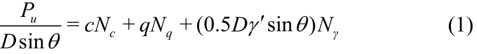
where Puis the collapse load for a pipeline foundation in the general shear failure, Dis the external diameter of the pipeline, θ =arccos(1 - 2 e/D) is the embedment angle (see Fig.1), e /D is the embedment-to-diameter ratio, “D s inθ” refers to the efficient width of the pipe-soil interface, which is related to the pipe penetration, c is the soil cohesion,q is the surcharge pressure (note: for e /D ≤ 0 .5, q is set to zero. For e /D > 0 .5, the pipeline embedment can be treated as e /D ≡ 0 .5 with an equivalent uniform surcharge pressure q = (e - 0 .5D)γ′, where γ′ is the buoyant unit weight of the soil), Nc, Nqand Nγare the bearing capacity factors for the cohesion, the distributed load, and the buoyant weight of soils, respectively[10].
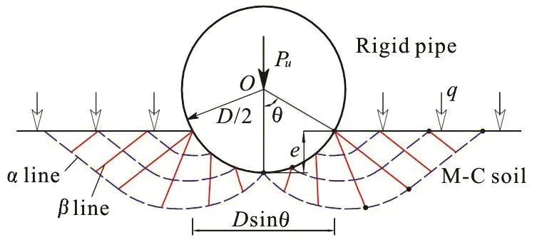
Fig.1 (Color onlin e) The slip- line field of a pipeline ( smooth) foundationonthesoilobeyingMohr-Coulombfailure
The aforementioned slip-line field solutions for predicting the bearing capacity of the pipeline foundations are extensions from the conventional bearing capacity theories for the strip footings. Figure 1 illustrates the slip-line stress field underneath a partially-embedded smooth pipeline for the soil obeying Mohr-Coulomb yield criterion, indicating that lines and lines are not perpendicular to each other due to the effect of the internal friction of soils.Neglecting the effects of the geometric curvature of the pipe (i.e., the embedment-to-diameter ratio e/D → 0 ), the adhesion of the pipe-soil interface (i.e.,the interfacial friction/adhesion coefficient μ=0),and the internal friction of the soil (i.e., the angle of internal friction φ=0) for the clayey seabed under undrained conditions, the slip-line field solutions can thereby be degenerated into Prandtl solutions for conventional strip footings, i.e., Nc=2+π . Parametric study showed that with the increase of the pipeline embedment, the value of Ncdecreases from Nc=2+π (e/ → 0 ) finally to Nc=4.0 (at e /D =0.5), indicating that the geometric curvature effect is not negligible. That is, for smooth pipelines on the undrained clayey seabed (μ=0and φ=0), if the circular pipeline foundations are directly simplified as conventional strip footings, the bearing capacity factor N c would be over evaluated, with an error up to 28.5%[9]. This geometric curvature effect on the beav ersionof the DNVGL Recommended Practice[11].ring capacity factor[9] was recently adoptedin the new With a further consideration of the influence of the internal frictionof thesoil,such a geometric curvature effect can become more prominent[10].
1.2 Lateral on-bottom stability
1.2.1 Pipe-soil interaction of submarine pipelines byDet Norske Veritas[4],the
Inthe design practicefor theon-bottom stability fundamental principle is the quasi-static decoupling between the hydrodynamic loads and the corresponding lateral soil resistance. When the drag force becomes larger than the lateral soil resistance, the lateral instability of the pipeline would be triggered.The lateral soil resistance is evaluated with an empirical pipe-soil interaction model proposed by Wagner et al.[12](commonly termed as the “Wagner model”), which was updated from the classical Coulomb's friction theory. For the pipelines on the sandy seabed, the lateral resistance (FR) is estimated by the Wagner model with the following expression
whereRfF andRpF are the sliding-resistance component and the passive-pressure component,respectively,0μ is the sliding resistance coefficient,recommended as 0.60 for the pipe on sands,SW is the submerged weight of the pipe per unit length,LF is the hydrodynamic lift force on the pipe per unit length, the characteristic area0.5A is half of the vertical cross sectional area of the soil displaced by the pipe embedment,0β is an empirical coefficient for the soil passive pressure. Under the monotonic loading condition, the values of0β are recommended within a relatively wide range, i.e., from “38” for γ′< 8 .6kN/m3to “79” for γ ′ > 9 .6kN/m3. It should be noticed that the Wagner model (Eq.(2)) is deduced from the results of a series of pipe-soil interaction tests, in which the hydrodynamic forces(including the drag and lift forces) were simulated with a mechanical actuator system, and the influence of the waves and (or) the currents on the seabed mobility was thereby ignored. As a presentational indicator for the flow-pipe-soil coupling effect, the local scour could not be realistically reproduced in such mechanical actuator simulations.
Unlike the terrigenous silica seabed materials,the carbonate deposits, abundant in shallow tropical waters, have distinguished features characterized by a high void ratio, a high compressibility due to the high initial void ratio and the crushable nature of individual particles, and a high friction angle due to angularity,roughness and interlocking of the particles. Experimental investigation indicated that the interactions between the pipeline and the carbonate soils are characterized by the following features: (1) approximately linear vertical load-displacement response, (2)relatively large lateral displacement to achieve the ultimate resistance, i.e., a pipeline on a low density calcareous sand may typically move laterally a distance two or more diameters before developing the ultimate soil resistance, compared with a distance typically about half to one diameter for a pipeline on silica sands, (3) cyclic loading induces larger embedment than for pipelines in the silica sand, (4)load-displacement response typically exhibits a ductile strain hardening response (except where the pipe is embedded below its equilibrium depth), and (5)significant excess pore pressure may accumulate under cyclic environmental loads acting on the pipe,as well as the wave pressure loading directly on the seabed, compared to the silica soils. This is because such sediments are more prone to degradation and compaction under cyclic loading and tend to have larger coefficients of consolidation than the typical silica sands, and consequently, the carbonate soils have a higher propensity for liquefaction than the silica soils[4].
1.2.2 Flow-pipe-soil coupling
In the submarine geological and hydrodynamic environments, several dynamic processes, including the shear flow above the seabed, the sediment transport along the seabed surface, and the excessive pore pressure in the soil, are generally coupled with each other and have a great influence on the on-bottom stability of submarine pipelines. As such,the triggering mechanism for the pipeline lateral instability involves not only the pipe-soil interaction,but also the flow-pipe-soil coupling process. Experimental observations[13]with a U-shaped oscillatory flow tunnel showed that, there always exist three characteristic states/stages during the process of the pipeline losing the lateral stability under a storm-like wave loading, i.e., (1) local-scour around the pipe, (2)pipe periodic-rocking with small amplitudes, and (3)pipe breakout from original location (see Fig.2).During this process, the local-scour always emerges as an indicator for the flow-pipe-soil coupling effect,observed to take place at the rear and the front of the partially-embedded pipeline. At the same time, the pipe periodic-rocking can induce an additional penetration of the pipe into the seabed. The occurrence of the pipeline instability is characterized by a distinct lateral displacement (e.g., dp/D > 0 .5),as shown in Fig.2(d). Such physical phenomena of the wave-induced lateral instability of the submarine pipeline were later reproduced and confirmed in wave flume tests[14].
Fig.2 (Color online) Characteristic stages during the process of the pipeline los ing la teral stabilit y under a sto rm-li ke w ave(a)Thelocalscouraroundthepipe,(b)The periodic rocking of the pipe, (c) The breakout of the pipe from its original location; and (d) The time development of the pipe lateral displacement and vertical settlement
The criteria for the pipeline lateral instability in waves and currents are crucial to the on-bottom stability design. Based on the similarity analyses, in the physical modeling in the gravitational wave flumes or the oscillatory flow tunnels, both the scaling of the Froude number (F r= Um/and that of the Keulegan-Carpenter number (K C = UmT/D)can be satisfied concurrently, where Umis the maximum velocity of the wave-induced water particle movement, is the gravitational acceleration, and T is the wave period. Note that although the scaling of the Reynolds number ( R e= UmD /ν, in which is the kinematic viscosity of the water) could not be satisfied concurrently with those of the Froude number and the Keulegan-Carpenter number, the values of Re for the models and that for the prototypes should be approximately within the same regime(e.g., the subcritical or supercritical regimes) to ensure similar flow features around the pipeline.
Based on the similarity analyses and the physical modeling experiments under the wave and current loading conditions, respectively[15,16], it was found that the controlling non-dimensional parameter of hydrodynamics for the pipeline lateral instability is the Froude number (F r), and another controlling parameter is the non-dimensional submerged weight of the pipelines ( G = Ws/γ ′D2). The KCnumber essentially controls the generation and the development of the vortices around the pipeline under the oscillatory flow in waves. A unified formulation of the criteria for the pipeline lateral instability in waves and currents can be expressed as
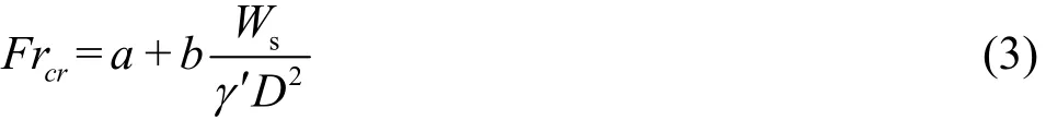
wherecrFr is the critical Froude number for the pipeline lateral instability, i.e.
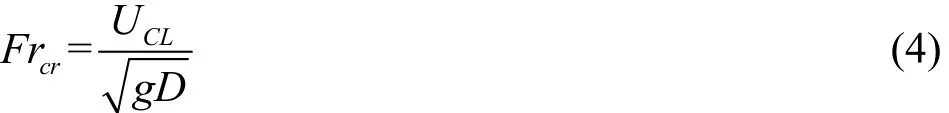
in which, UCLis the corresponding critical velocity for the pipe lateral instability. In Eq.(3), the two parameters (a and b) are relative to the hydrodynamic loads (the periodic waves or the steady currents),the end-constraint conditions of the shallowly-embedded pipes (anti-rolling or freely-laid), and the soil properties of the seabed. On the basis of the results of a series of experiments, the values of these two parameters are determined as (a,b ) =(0.07,0.62) for the anti-rolling pipes in waves, (a,b ) =(0.042,0.38) for the freely-laid pipes in waves (5 < K C< 2 0). But for the freely-laid pipes in steady currents (K C → ∞ ),(a,b ) =(0.102,0.423), indicating that the pipes are more stable in currents than in waves due to the inertia effect of wave movements. Note that the above recommended values for the two parameters a and b are based on the results of model tests on a uniform medium sand-bed (the mean diameter of sand particles d50=0.38mm). The particle size is closely related to the sediment transport and further affects the lateral stability of the pipeline.
The instability criteria in the unified formulation of Eq.(3) provide alternative expressions to the Wagner model (Eq.(2)) for evaluating the wave/current induced on-bottom stability of a shallowlyembedded pipeline, as discussed by Freds?e[2].Following the updated criteria, a flow-structure-soil coupling method (termed as the FSS method) for the wave-induced pipeline stability on the sandy seabed was proposed[17]. A comparison between the FSS method and the existing DNV Recommended Practice indicated that their results are generally comparable.With the increase of the Froude number, the generalized method in the DNV practice becomes more conservative than the FSS method, indicating that the flow-structure-soil coupling effect becomes more remarkable.
1.2.3 Influence of seabed slope angle
As the offshore industries move from shallow to deep waters, there has been a rapid development of the ocean engineering, e.g., at the continental slopes in the South China Sea. In deeper waters, the ocean current becomes the prevailing hydrodynamic load acting on submarine pipelines. Meanwhile, the sloping seabed is very common, especially at the continental slopes.These specific factors might have significant influence on the stability of deepwaterpipelines. Based on the dimensionless analyses, a coefficient of the ultimate lateral-soil-resistance (ηα) was proposed[18],which is defined as the ratio of the ultimate lateral soil resistance FR(= FD- WSsin α ) to the corresponding pipe-soil normal contact force FC(= WScosα -FL),where is the seabed slope angle, andDF is the hydrodynamic drag force on the pipe per unit length.Experimental results indicate that for both the upslope and the downslope instability, the values ofαη are larger than those for the horizontal seabed, and increase nonlinearly with the increase of the slope angle (absolute values).
1.2.4 Analytical solution to ultimate lateral soil resistance anal
The pl a inn d eisc tartaei nt healta stthoe- pp llaa ssttiicc fzi no int ee ed leevme e lon pte(dF Ei n)the proximity of the pipeline when losing the lateral stability is quite similar to that for the passive failureof the conventional retaining Although the pipeline lateral instability is characterized by distinct horizontal displacements in the macroscopic view (see Fig.2(d)), the development of the plastic zone in the soil around the partially-embedded pipeline demonstrates a progressive failure mode. An analytical model for the current-induced pipeline instability on a sloping sandy seabedwas further proposed by Gao et based on the Coulomb's theoryof the passive earth pressure and it was verified by the existing full scale test results. The analytical solution for the ultimate lateral soil resistance (FR) to the pipeline partially-embedded into a horizontal sandy seabed(α=0) can be simplified as

where Rpf( ≡ FRp/FRf=cosω c o s(β -δ+ φ ) /[ sin φ·sin(β -δ-ω)] is the ratio of the passive-pressure component to the sliding-resistance component,Kp={cosφ / c osφ ′)1/2-[sin(φ+ φ ′) s in φ ]1/2}2is the passive pressure coefficient, is the internal friction angle of the sands, φ′ is the mobilized friction angle along the virtual retaining wall, which is supposed to be perpendicular to the seabed surface with the same length as the pipe embedment (Note: as the angle φ′is usually partially mobilized with less than φ/3[7],choosing the value of φ′ as nil would be a conservative estimate for the engineering design);β=π /2-3θ/4,ω=arctan[(E1sinφ ′- Wb) /(E1·cos)]φ′, in which the total passive earth pressure on the virtual retaining wall1( )E can be calculated with Coulomb's theory of the passive earth pressure,bW is the submerged weight of the soil wedge carried by the pipe whilelosing lateral stability,δ=arctan[FD/(WS- FL)]- 3 θ/4 is the the pipe-soil interfacial friction, the absolute values of which should not be larger than its critical valuecrit()δ, i.e.,δ≤δcrit(otherwise, the pipe would breakout from its in-place location through the pipe-soil interfacial slippage). The critical interfacial friction anglecritδ can be evaluated with δcrit=arctan[sin φ cosψ /(1-sin φ s in ψ ) ], in which isthe angle of the soil dilation. Parametric study indicates that the effect of the slope angle on the pipe lateral soil resistance is significant. Both the critical pipeline embedment to keep the pipe stable on the sloping seabed and the corresponding passive-pressure component decrease approximately linearly with the increase of the slope angle (negative for downslope instability)[20].
2. Tunnel-erosion and vortex-induced vibration of pipelines
2.1 Pipeline spanning triggered by tunnel erosion
In addition to the aforementioned lateral instability, submarine pipelines are also under threat from the tunnel-erosion of the neighboring soil. With the shear flow near the seabed, the spanned pipeline may undergo VIVs.
The bed-load, the suspended-load and the washload related with the transports of the granular sediment have been investigated intensively[21]. The triggering mechanism for the spanning of a partiallyembedded pipeline was intuitively attributed to the sediment transport or the local scour at the seabed surface. But comparative flume experiments showed that when an impermeable plate is laid at the upstream of the test pipe in the steady flow, the pressure gradient could be greatly reduced and the occurrence of the pipeline spanning is effectively prevented[22].Physical modeling in water flumes and numerical simulations were later conducted to investigate the local underneath scour and the self-burial of the pipeline in ocean currents or waves[23-26]. It is well recognized that the pipeline spanning is essentially not due to the progressive development of the local scour,but the seepage failure of the underlying soil (termed as the tunnel-erosion). The tunnel-erosion plays a decisive role in triggering the pipeline spanning (see Figs.3(a),3(b)).
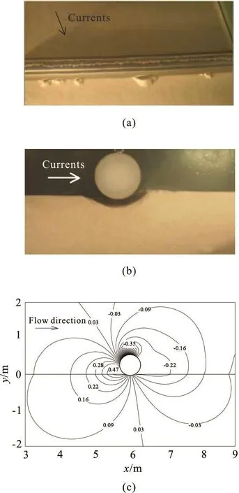
Fig.3 lu ti ons of pi pel ine span ning indu ced bytunnel erosion:( a)Initiation of seepagefai- lureofsan ds,(b) Co mpl etesusp ensi onofthepipe , (c) Numericalresult softhe con tourf orflow -pressureand seepage-pressurearoundthepipe(kPa)( D = 0.60m , e /D = 0.05,U =1.0m/s
A flow-pipe-seepage sequential coupling FE model[26]was established for implementing the multiphysical coupling between the water flow-field and the soil seepage-field by simultaneously solving the two-dimensional Reynolds-averaged Navier-Stokes(RANS) and continuity equations, and the Laplace's equation for the steady seepage flow. Numerical results indicated that the pressure drop between the upstream (positive pressure) and the downstream(negative pressure) of the pipeline can induce seepage flows within the underlying soils(see Fig.3(c)). The maximum value of the hydraulic gradient inducing obliquely upward seepage is at the downstream corner of the pipe (the intersection point between the embedded pipe and the seabed surface), as was confirmed by the flume experimental observations. As observed in the series of flume tests[26], although the local scour always emerges around the pipeline, the tunnel- erosion plays a vital role in the process of the pipe being suspended as the result of the underlying soil being washed away. A critical hydraulic gradient was then derived for the oblique seepage failure of the sand-element tangent to the pipe surface

where icr0=(1 - n ) (s - 1 ) is the conventional critical hydraulic gradient for the vertical seepage failure, n is the porosity of sands, is the specific gravity of the sand grains. As indicated by Eq.(6), the critical hydraulic gradient for the oblique seepage failure is further affected by the pipe embedment and the internal friction angle of the sands. Similarity analyses show that the pipeline spanning initiation is predominantly controlled by a revised Shields number
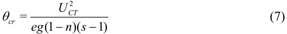
with the pipe embedment (e) as a characteristic length, where UCTis the critical flow velocity for the pipeline spanning induced by the tunnel-erosion.Based on the results of the parametric study, an empirical relationship was then established for evaluating the spanning initiation of the pipeline with an embedment (e) at the critical flow velocity (UCT)
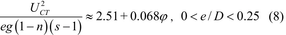
which indicates that the revised Shields number changes approximately linearly with the internal friction angle of the sands.
As above stated, if the flow velocity of the ocean current is larger than its critical value predicted with Eq.(8), the pipeline spanning can be induced by the tunnel-erosion mechanism for the partially-embedded pipelines. Also, the pipeline spanning may take place due to the initial unevenness of the seabed surface.When the frequency of the vortex-shedding becomes close to the natural frequency of the pipeline spanning,the VIV could be further triggered, which will be discussed in detail in Section 2.2.
2.2 Vortex-induced vibration of submarine pipelines
The VIV is a typical fluid-structure interaction response, as the major cause for the fatigue damage of offshore structures. In the steady flow, the lee-wake vortex is shed from a fixed circular cylinder with specific frequencies obeying the Strouhal law, i.e.,fs= StU/D, where Stis the Strouhal number, which is a function of the Reynolds number ( St≈ 0 .18, in the subcritical regime 0 .3× 1 03< Re<3.0× 1 05).When the vortex shedding frequency (fs) is close to the natural frequency ( fN), the lock-in phenomenon(initiallyobserved and described by Bishop and Hassan[27]) may take place, i.e., the vortex shedding frequency and the vibration frequency (f) are locked together. The range of the VIV excitation(synchronization regime) is commonly characterized by the reduced velocity Vr(=U / fND). The synchronization regime and the corresponding amplitude and frequency responses of the VIVs are the main concerns for the engineering practice.
One of the most conceptually simple situations of the aforementioned fluid-structure interaction is the case of an elastically-mounted rigid cylinder constrained to vibratetransversely againsta uniform free stream[28]. Existing experiments indicate that, for a wall-free cylinder (elastically-mounted), the VIV synchronization regime depends mainly on the mass ratio m*. Note that m*=4 m /, where m is the mass of the cylinder per meter, ρwis the mass density of the water. The non-dimensional peak amplitude of the vibrations(=Amax/D ) depends however primarily on the combined mass-damping parameter ( m*ζ) , where Amaxis the peak amplitude and ζ is the damping ratio of the elasticallymounted cylinder in the water. Several forms of the mass-damping parameter, also termed as the “stability parameter” (e.g., the Skop-Griffin parameter SG=were proposed and employed for correlating with the peak amplitudes.
There are two distinct types of the VIV amplitude responses in the wide range of the combined mass-damping parameter*( )mζ :
(1) Under the high-()mζ*conditions (e.g.,, in the classical VIV tests in the air by Feng[29]), two branches (initial and lower) are observed in the plot of the variations of the dimensionless VIV amplitude A*(=A/D) against the reduced velocity Vr. In the “initial” excitation branch,the vibration amplitude increases gradually to its maximum value ( Amax), then drops to the “l(fā)ower”branch.
(2) Under the low-(m*ζ) conditions ((m*+CA)ζ < 5 00), in the VIV amplitude response, however, three branches (initial, upper and lower) are observed: An “upper” branch with large vibration amplitudes can be additionally excited between the initial and lower branches (see Fig.4(a)).
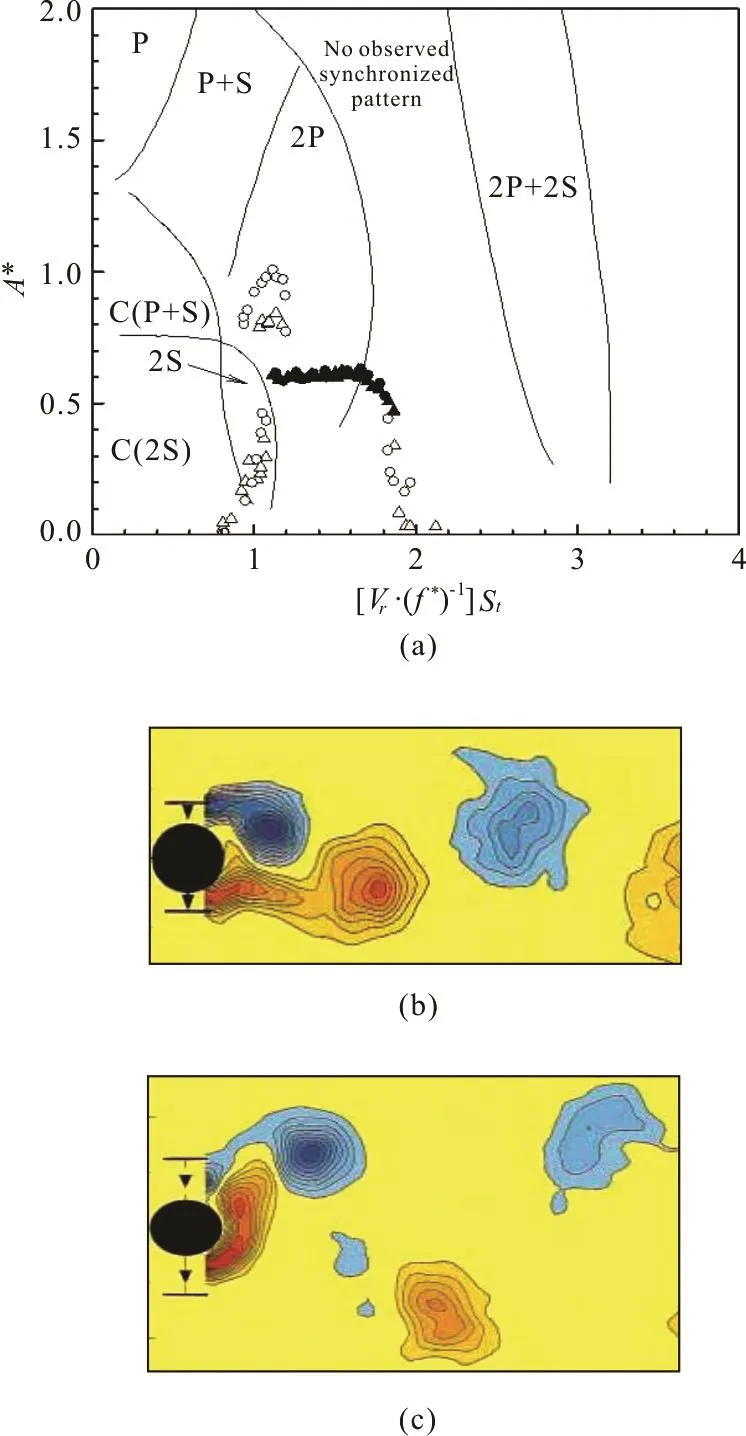
Fig.4 (Color online) Correlation of VIV amplitude response with wake modes: (a)Variation of A * against (V / f * ) and r thecorrespondingwakemodes.Circles:m*=1.19, ( m * + C A )ζ = 0.0110, Triangles: m *=8.63,(m *+ C A)ζ = 0.0145 (Solid symbols represent the “l(fā)ower” branch regimes). Transition of wake modes: (b) The “2S” wake mode at the “initial” excitation branch ( A *=0.33, R e = 3.0× 1 03), ( c) The “2P” wake mode at the “ upper” excitationbranch( A *=0.81,Re = 3.1× 1 03).Note: Bwliusee vcoornt ours show clockwise vorticity, red anticlock-
It should be noticed that under the high-()mζ*conditions, the vibration amplitude response experiences a“jump” only once, Nevertheless, under the low-()mζ*conditions, twice mode transitions of the vibration response are observed, which are either hysteretic or of intermittent switching[30]. It is found that the mode transition between the “initial” and“upper” branches is hysteretic, and the mode transition from the “upper” to the “l(fā)ower” branches with high values ofrV sees intermittent switching.As illustrated in Figs.4(b) and 4(c), while the mode for the vibration amplitude is switched from the “initial”to “upper” branches, the corresponding vortex shedding shifts from “2S” to “2P” modes, i.e., a jump between “2S” ? “2P” vortex wake modes. As plotted in Fig.4(a) of the amplitude responses and the corresponding vortex modes for two different mass ratios (=m*1.19 and 8.63, under the low-()mζ*conditions), the wake modes and their transitions are mainly controlled by two dimensionless parameters,i.e., A*(=A/D ) and (Vr/ f*) St, where f*(=f / fN) is the ratio between the vibration and natural frequencies[28].
2.2.2 Flow-pipe-soil coupling mechanism
The physical process from the erosion-induced spanning to the vortex-induced vibration of a submarine pipeline involves a complex flow-pipe-soil coupling. In such a multi-mechanics coupling process,the local scour, the lee-wake shedding and the pipeline vibration are fully- or partially-coupled[31-34]. As shown in Figs.5(a) and 5(b), two typical phases of the local scour development around an elasticallymounted pipe are identified by experimental observations as follows[32]:
(1) Phase-I: Scour beneath the pipe without the VIV
The sand particles beneath the pipe are washed away by the tunnel-erosion beyond a critical flow velocity, which induces the occurrence of the pipeline spanning with a gap between the pipe bottom and the underlying eroded soil surface. The local scour depth(vertical) and width (horizontal in the streamline) are then further enlarged for a considerable period, during which the pipe vibration is nearly imperceptible.
(2) Phase II: Coupling between the local scour and the VIV of the pipe
When the scour depth becomes large enough, the VIV of the pipe takes place. Strong dynamic interactions between the local-scour and the VIV are clearly observed: the scour depth becomes even larger, at the same time, the vibration amplitude of the pipe is enhanced, and finally the local-scour and the VIV come into an equilibrium state. Due to the wall-proximity effect, the local scour may affect not only the vibration amplitude, but also the frequency. The flume observation shows that with the development of the local scour, the vibration frequency is gradually decreased by up to 20% and finally approaches to a constant value to reach the equilibrium state (see Fig.5(c)).
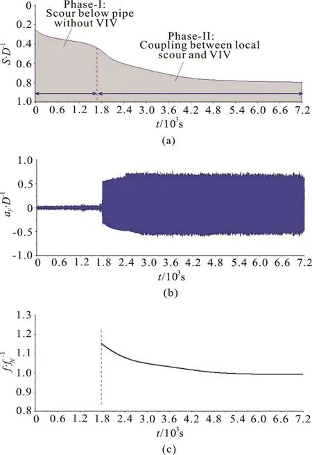
Fig.5The time d of the coupling be- tween the local-scour and the VIVs ofthe (a) Di- men sionless scour depth S /D , (b) Dimensionless vibra- tiondisplacement a y/D,and(c)Dimensionlessvibra- tion frequency f /fN (e0/D = -0 .25 ,m *=3.8 6, f N= 1.22Hz,(m * + C A )ζ = 0.09,Vr =0.63,d50= 0.38mm)
As aforementioned, for the VIV responses of the wall-free cylinders, the dimensionless peak amplitudeis predominantly controlled by the combined mass-damping parameter (stability parameter) of the fluid-structure interaction systems. Figure 6 shows the variations ofagainst the stability parameter(m * + CA)ζ for different gap-to-diameter ratios,where CAis the added mass coefficient, CA=1.0 for the circular cylinder.As indicated by the classicalcurve (see Fig.6), under the wall-free conditions (e.g., e0/D > 1 .0), the values of the peak amplitude keepconstant≈ 1 .1) with the increase of the stability parameter for (m*+ C )ζ<A 0.05, After (m*+ CA)ζ ≥ 0 .05,decreases gradually to zero.
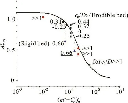
Fig.6 (Color online) Variationsof peak amplitudes of VIV against the com bi ned ma ss-damping para meterEffectofinitialgap-to-diameterratio (negativ e value s mean that th e pip e is initially embedded into theseabed). Wall-free conditions: ● Govardhan and ——Skopand Balasubramania, Wall-proximityconditions: Yang et for the rigid wall, ■Yang etfor erodiblesand-bed
Under the wall-proximity conditions(e.g.,e /D < 1 .0), for certain values of (m*+, the0peak amplitude drops remarkably with the decrease of the gap-to-diameter ratio (see Fig.6). In the steady shear flow at the seabed, the vortex-shedding from a cylinder is mainly controlled by the Reynolds number(R e)and the gap-to-diameter ratio (e0/D). Under certain flow conditions (e.g., in the subcritical regime),with the decrease of the gap-to-diameter ratio, the lower shear layer along the cylinder bottom and the wall shear layer would interact with each other. The vortex-shedding would be suppressed if the positive vorticity in the lower shear layer can be efficiently counteracted by the opposite-signed vorticity in the wall shear layer near a rigid pane boundary, while the critical gap-to-diameter ratio approaches to a constant value ( e0/D )cr=0.20 for Reynolds numbers Re > 0.6× 1 03[36].
For the spanned pipelines at the seabed, their VIV responses are also influenced by the erodible soil,i.e., the time-dependent wall-proximity effect. Given the combined mass-damping parameter (e.g.,=0.127, see Fig.6) of a pipeline near the erodiblesand-bed,with thedecreaseof the gap-to-diameter ratio e0/D from 0.44 to -0.25, the peak amplitudeapproximately varies between 0.92 and 0.72, close to the value of 0.83 under the wall-free condition. This implies that the effect of the gap-to-diameter ratio on the peak amplitude response is not negligible, nevertheless, the development of the local-scour could significantly reduce such wall-proximity effect on the VIV responses.
3. Competition mechanisms between instability mo- des
Submarine pipelines are a special type with shallow foundations and a circular configuration,involving various instability modes, e.g., the lateral instability, the tunnel erosion, and the VIVs. As described previously, both the lateral-instability and the tunnel-erosion involve the fluid-structure-soil interactions. The respective physical mechanisms of the two processes are different, i.e., the lateral instability is dominated by the Froude number(Eq.(4)), while the tunnel-erosion is dominated by the revised Shields number (Eq.(7)). Based on correlation analyseson such two processes (with the tunnel-erosion predicted by Eq.(8), the lateral soil resistance predicted by Eq.(5), in combination with the pipeline hydrodynamics predicted by Morison equations with consideration of the wall-proximity effect[39]), the critical flow velocity for the instability of the fluid-pipe-soil coupling system can be expressed as[40]:
where remb,His the reduction coefficients for the horizontal drag force suggested in the DNV recommended practice[4], (e/D)Tis the embedmentto-diameter ratio for transition of instability mechanisms.
Equation (9) indicates that, if the basic parameters for the sandy seabed and the ocean current are given, the critical flow velocity is predominantly related to the pipe embedment and the submerged weight of the pipe. As shown in Fig.7, the instability envelope for the fluid-pipe-soil coupling system can bedescribed with three key parameters:the embedment-to-diameter ratio (e/D ), the dimensionless submerged weight of pipe (G), and the corresponding critical flow velocity (Ucr). It can be said that the lateral-instability of the pipe and the tunnel-erosion of the sand are two competitive processes. The tunnel-erosion is more prone to emerge than the lateral-instability for shallowly embedded pipelines, i.e., with the increase of e /D, the tunnel-erosion could be suppressed and then the lateral-instability becomes easier to be induced. For a given value of e /D, with the decrease of the dimensionless submerged weight of the pipeline, the lateral instability is more likely to be triggered than the tunnel erosion.
Fig.7 (Color on linr) Inst ability envelope fo r the fluid-p ipe-soil couplingsystem(sand:φ=43o,n=0.53,γ′= 7 .6 0kN/m3, s = 2.65, water: ρ w =1.0×10³ kg/m3, ν = 1.5×10 -6m2/s, pipe: D = 0.50m )[40]
4. Concluding remarks
The advances of the studies of the instability of submarine pipelines are reviewed with the focus on the flow-pipe-soil coupling mechanisms and the theoretical predictions. The instability modes of a fluid-pipe-soil coupling system are shown with distinct diversity in physical mechanisms, including the vertical on-bottom instability (bearing capacity of pipeline foundations), the lateral-instability of the pipe,the tunnel-erosion of the underlying soil, and the vortex-induced vibrations of free spanning pipelines.It is indicated that these instability modes are not isolated, but always competitive between each other in the submarine geological and hydrodynamic environments.
Offshore oil and gas exploitations have now turned from shallow waters to deep/ultra-deep waters all over the world. In view of the deep-water oil and gas exploitations, the prospects and several scientific challenges for predicting the instability of a longdistance submarine pipeline are presented as follows.
The subsea hydrodynamics and the geological conditions are generally uniform in the shallow waters,but become more complex for the long-distance pipelines crossing from the wellheads in the deeper waters to shallow water zones. With the increase of the water depth, the surface wave-induced waterparticle oscillations near the seabed would be gradually weakened and finally vanish in the water approximately deeper than one wavelength. Ocean currents including the turbidity currents (driven by density and temperature gradients, or sometimes resulted from the submarine seismic loading) often exist even in the deep waters, which are related to the submarine debris or landslide especially at continental slopes. Meanwhile, in the wave-current coexisting fields, the wave-current combination effects in the multi-physical processes of sediment transport and soil liquefaction could be significant for the pipeline on-bottom stability. For deepwater pipelines, another dominant load comes from the high internal temperature/HT (up to 180oC) and the high pressure/HP (up to 10MPa or more), which may cause the pipeline to expand and even globally buckle along the seabed surface. The global bucking of HP-HT pipelines is, in essence, the elastic instability of the long/hollow cylindrical structure conveying heated fluids, under the random and asymmetric seabed boundary conditions. In the geotechnical design for a long-distance pipeline, the soil properties of the wide-spreading seabed are commonly obtained from limited drilling holes along the potential route, thus the random properties of the seabed should be taken into account. At the same time,the soil resistance to a partially or fully buried pipeline is not uniform in the lateral and vertical directions,which would further have influence on the general modes of the global buckling. The long-distance pipelines across various water depths may encounter different specific loads (waves, currents, and thermal effects), and soil types (sandy, clayey, and silty seabed). As such, the instability modes at various locations of a long-distance pipeline are variable, and their underlying mechanisms could be competitive with different risk levels.
[1] Randolph M. F., Gaudin C., Gourvenec S. M. et al. Recent advances in offshore geotechnics for deep water oil and gas developments [J]. OceanEngineering, 2011, 38:818-834.
[2] Freds?e J. Pipeline–seabed interaction [J]. Journal of Waterway, Port, Coastal, and Ocean Engineering, 2016,142(6): 03116002.
[3] Zan Y. F., Yang C., Han D. F. et al. A numerical model for pipelaying on nonlinear soil stiffness seabed [J].Journal of Hydrodynamics, 2016, 28(1): 10-22.
[4] Det Norske Veritas. On-bottom stability design of submarine pipelines [Z]. DNV Recommended Practice DNV-RP-F109, 2010.
[5] CHEN W. F. Limit analysis and soil plasticity [M].Amsterdam, The Netherlands: Elsevier, 1975.
[6] Potts D. M., Zdravkovi? L. Finite element analysis in geotechnical engineering: Application [M]. London, UK:Thomas Telford Ltd, 2001.
[7] Craig R. F. Craig's soil mechanics [M]. Oxford, UK: Spon Press, 2004.
[8] Zhao B., Gao F. P., Luo C. C. Soil plasticity and shear failure properties of pipeline foundation [J]. Ship and Ocean Engineering, 2008, 37(2): 95-99(in Chinese).
[9] Gao F. P., Wang N., Zhao B. Ultimate bearing capacity of a pipeline on clayey soils: Slip-line field solution and FEM simulation [J]. OceanEngineering, 2013, 73:159-167.
[10] Gao F. P., Wang N., Zhao B. A general slip-line field solution for the ultimate bearing capacity of a pipeline on drained soils [J]. Ocean Engineering, 2015, 104: 405-413.
[11] Det Norske Veritas Pipe-soil interaction for submarine pipelines [Z]. DNVGL Recommended Practice DNVGLRP-F114, 2017.
[12] Wagner D., Murff J. D., Brennodden H. et al. Pipe-soil interaction model [J]. Journal of Waterway, Port, Coastal and Ocean Engineering, 1989, 115(2): 205-220.
[13] Gao F. P., Gu X. Y., Jeng D. S. et al. An experimental study for wave-induced instability of pipelines: The breakout of pipelines [J]. Applied Ocean Research, 2002,24(2): 83-90.
[14] Teh T. C., Palmer A. C., Damgaard J. S. Experimental study of marinepipelines on unstable and liquefied seabed[J]. Coastal Engineering, 2003, 50(1-2): 1-17.
[15] Gao F. P., Gu X. Y., Jeng D. S. Physical modeling of untrenched submarine pipeline instability [J]. Ocean Engineering, 2003, 30(10): 1283-1304.
[16] Gao F. P., Yan S. M., Yang B. et al. Ocean currents-induced pipeline lateral stability [J]. Journal of Engineering Mechanics, 2007, 133(10): 1086-1092.
[17] Gao F. P., Jeng D. S., Wu Y. X. An improved analysis method for wave-induced pipeline stability on sandy seabed [J]. Journal of Transportation Engineering, 2006,132(7): 590-596.
[18] Gao F. P., Han X. T., Cao J. et al. Submarine pipeline lateral instability on a sloping sandy seabed [J]. Ocean Engineering, 2012, 50: 44-52.
[19] Han X. T. Ocean current induced on-bottom instability of submarine pipelines on a sloping seabed [D]. Master Thesis, Beijing, China: Graduate University of Chinese Academy of Sciences, 2012(in Chinese).
[20] Gao F., Wang N., Li J. H. et al. Pipe-soil interaction model for current-induced pipeline instability on a sloping sandy seabed [J]. Canadian Geotechnical Journal, 2016, 53(11):1822-1830.
[21] Chien N., Wan Z. H. Mechanics of sediment transport [M].New York, USA: American Society of Civil Engineers Press, 2014.
[22] Chiew Y. M. Mechanics of local scour around submarine pipelines [J]. Journal of Hydraulic Engineering, ASCE,1990, 116(4): 515-529.
[23] Sumer B. M., Truelsen C., Sichmann T. et al. Onset of scour below pipelines and self-burial [J]. Coastal Engineering, 2001, 42(4): 313-335.
[24] Liang D., Cheng L. A numerical model of onset of scour below offshore pipelines subject to steady currents [C].Proceedingsof the First International Symposiumon Frontiers in Offshore Geotechnics. Perth, Australia, 2005.
[25] Yang B., Gao F. P., Wu Y. X. Numerical study of the occurrence of pipeline spanning under the influence of steady current [J]. ShipBuilding of China, 2005,46(Suppl.): 221-226(in Chinese).
[26] Gao F. P., Luo C. C. Flow-pipe-seepage coupling analysis on spanning initiation of a partially-embedded pipeline [J].Journal of Hydrodynamics, 2010, 22(4): 478-487.
[27] Bishop R. E. D., Hassan A. Y. The lift and drag forces on a circular cylinder in a flowing field [J]. Proceedings of the Royal Society of London, Series A: Mathematical and Physical Sciences, 1964, 277(1368): 51-75.
[28] Govardhan R., Williamson C. H. K. Modes of vortex formation and frequency response of a freely vibrating cylinder [J]. Journal of Fluid Mechanics, 2000, 420:85-130.
[29] Feng C.-C. The measurement of vortex induced effects in flow past stationary and oscillating circular and D-section cylinders [D]. Master Thesis, Vancouver, Canada: The University of British Columbia, 1968.
[30] Khalak A., Williamson C. H. K. Motions, forces and transitions in vortex-induced vibrations at low mass-damping[J]. Journal of Fluidsand Structures, 1999, 13(7-8):813-851.
[31] Sumer B. M., Freds?e J. The mechanics of scour in the marine environment [M]. Singapore: World Scientific,2002.
[32] Gao F. P., Yang B., Wu Y. X. et al. Steady currents induced seabed scour around a vibrating pipeline [J]. Applied Ocean Research, 2006, 28(5): 291-298.
[33] Zhao M., Cheng L. Numerical investigation of local scour below a vibrating pipeline under steady currents [J].Coastal Engineering, 2010, 57(4): 397-406.
[34] Zhao M., Cheng L., An H. W. Numerical investigation of vortex-induced vibration of a circular cylinder in transverse direction in oscillatory flow [J]. Ocean Engineering,2012, 41: 39-52.
[35] Skop R. A., Balasubramanian S. A new twist on an old model for vortex-excited vibrations [J]. Journal of Fluids and Structures, 1997, 11: 395-412.
[36] Lei C., Cheng L., Armfield S. W. et al. Vortex shedding suppression for flow over a circular cylinder near a plane boundary [J].OceanEngineering,2000,27(10):1109-1127.
[37] Yang B., Gao F. P., Wu Y. X. et al. Experimental study on vortex-induced vibrations of submarine pipeline near seabed boundary in ocean currents [J]. ChinaOcean Engineering, 2006, 20(1): 113-121.
[38] Yang B., Gao F. P., Jeng D. S. et al. Experimental study of vortex-induced vibrations of a pipeline near an erodible sandy seabed [J]. OceanEngineering, 2008, 35(3-4):301-309.
[39] Jones W. T. On-bottom pipeline stability in steady water currents [J]. Journal of PetroleumTechnology, 1976,30(3): 475-484.
[40] Shi Y. M., Gao F. P. Lateral instability and tunnel erosion of a submarine pipeline: Competition mechanism [J].Bulletinof Engineering Geology and the Environment,2017, DOI: 10.1007/s10064-017-1073-9(in Press).
July 28, 2017, Revised August 3, 2017)
* Project supported by the National Natural Science Foundation of China (Grant Nos. 11372319, 11232012), the Strategic Priority Research Program (Type-B) of CAS (Grant No. XDB22030000).
Biography: Fu-ping Gao (1973-), Male, Ph. D., Professor
 水動(dòng)力學(xué)研究與進(jìn)展 B輯2017年5期
- 水動(dòng)力學(xué)研究與進(jìn)展 B輯的其它文章
- On the clean numerical simulation (CNS) of chaotic dynamic systems *
- Flowstructure and phosphorus adsorption in bed sediment at a 90° channel conflunce
- Determination of urban runoff coefficient using time series inverse modeling *
- An ISPH model for flow-like landslides and interaction with structures *
- Capillary-gravity ship wave patterns *
- Stationary phase and practical numerical evaluation of ship waves in shallow water *