
Optimization design of multiphase pump impeller based on combined genetic algorithm and boundary vortex flux diagnosis *
2017-03-14 07:06:41JinyaZhang張金亞ShujieCai蔡淑杰YongjiangLi李泳江XinZhou周鑫
水動力學研究與進展 B輯 2017年6期
Jin-ya Zhang (張金亞), Shu-jie Cai (蔡淑杰), Yong-jiang Li (李泳江), Xin Zhou (周鑫),
Yong-xue Zhang (張永學)
College of Mechanical and Transportation Engineering, Beijing Key Laboratory of Process Fluid Filtration and Separation, China University of Petroleum, Beijing 102249, China, E-mail: zhjinya@163.com
Introductio n
The oil well fluid is a mixture of the oil, the water and the natural gas. The traditional technology for the well head transport is to separate the gas from the oil and the water using a gas-liquid separator, and then to transport the liquid by oil pumps and the gas by compressors, respectively. The multiphase transporting system developed in recent decades can be directly used to transport the gas-liquid mixture without separation equipment at the wellhead. Compared with the traditional technology, the multiphase transporting technology shows remarkable economic benefits in recent years[1,2]. Thus, as a core of the multiphase transporting technology, the multiphase pump becomes a current research focus in oil fields.
The rotodynamic multiphase pump (RMMP)with features of large wrap angle and long flow passage is suitable for the mixture transport. The complex state of the gas-liquid two-phase flow in the multiphase pump impeller makes the separation of the gas and the liquid inevitable due to the centrifugal force. In severe cases, the gas-liquid separation often leads to the formation of air pocket, to affect the normal transportation of the two-phase flow to some extent. A reasonable geometry structure of the impeller is important for avoiding the gas-liquid separation and improving the hydraulic performance of a multiphase pump. Zhu et al.[3]comprehensively considered the hydraulic design method of the axial impeller and inducer with the properties of transporting the mixture and then put forward a basic geometry structure, a hydraulic design method, as well as a value range of key geometrical parameters of the RMMP impeller. Cao et al.[4]presented a hydraulic design method of the RMMP impeller through combining the inverse design and the computational fluid dynamics (CFD) analysis. Zhang et al.[5]derived the velocity gradient equation in the meridian plane of the impeller, and put forward a design method of the multiphase pump impeller based on the 2-D hydraulic design theory. Kim et al.[6]improved the hydrodynamic performance of a multiphase pump by optimizing the impeller and the diffuser using the design of experiment techniques and the response surface method. In the optimization procedure, the lengths of the inlet and outlet regions of the meridional plane and the blade angles are selected as the design variables.
The hydraulic performance of an impeller is directly influenced by its shape, which is determined by many geometrical parameters. Due to the interactions among these parameters, the impellers designed with the existing methods need to be further optimized.With the help of the CFD technology and various optimization algorithms, various integrated impeller design methods were developed. It was amply shown that the application of the GA is effective in the optimization design of turbomachinery impellers[7].Liu and Zhang[8]constructed an automatic optimal design platform and optimized a centrifugal pump impeller by combining the impeller parametric method, the multi-objective GA, and the numerical calculation software NUMECA. Zhang et al.[9]put forward a multi-objective and multi-operating mode optimization method for designing the multiphase pump impeller using the combination of the CFD, the BP Neural Network, and the NSGA-II. During the optimization, the CFD results were used to train the neural networks and find the objective functions. Lee et al.[10]conducted a systematic optimization study on the GA-based design optimization procedure to search the complex design landscape in an efficient and parallel manner. In their study, the fitness evaluations in the optimization procedure were performed with the RANS-based CFD simulations and the mesh regeneration was automatically carried out through a scripting process within the grid generator. Djavareshkian and Latifi[11]optimized a wind turbine airfoil using the GA-based optimization method, the CFD, and the artificial neural network (ANN), which was used as a surrogate model to reduce the computational cost and time. Goto et al.[12]developed a computer-aided system for the hydraulic design of the flow passage components of a centrifugal pump. The system has integrated the 3-D CAD model reconstruction, the grid automatic generation, the CFD calculation analysis, and the 3-D inverse problem design. The results can be directly applied to a rapid prototype to greatly shorten the design cycle of the centrifugal pump. Arturo et al.[13]optimized the location of impellers on the central shaft of a tall stirred tank using a combination of the evolutionary programing and the CFD. Derakhshan et al.[14]used a global optimization method based on the ANN and the Artificial Bee Colony algorithm along with a validated 3-D Navier-Stokes flow solver to redesign the impeller geometry and improve the performance of a Berkeh 32-160 pump. ?idonis et al.[15]developed a generic optimisation method for Pelton turbine runners using CFD. Two different initial runners are optimized to achieve more generic results based on this method.
The BVF diagnosis, based on the vortex dynamic theory, can amplify the defect of the local flow by analyzing the flow on the wall of the impeller using the BVF analysis method, which can be used for identifying the parts with defects and providing a direct evidence for improving the design. Based on viscous flow equations, Wu and Wu[16]developed a complete theory of the boundary vortex dynamics and showed that the vortex flux on the object plane was not only the source of the lift force and the resistance,but also the cause of the unsteady separated flow. In this theory, the force and the momentum on the object plane can be calculated by the integration of the vortex flux; the balance between the lift force and the resistance can be achieved by controlling the vortex flux distribution on the object plane. Thus, the theory is applicable to the cases of any Mach number and Reynolds number, as well as both steady and unsteady flows. Zhang et al.[17]optimized the hydraulic performance of a high-specific speed centrifugal pump impeller by using the BVF diagnostic method. Li et al.[18]diagnosed the flow field distribution in the starting process of a centrifugal pump by using the vorticity dynamics method.
Many hydraulic design and optimization methods were proposed to improve the hydraulic performance of the RMMP. Among various optimization methods,the bench tests of pumps with impellers of different geometry parameters are time- and cost-consuming.For the use of the optimization method for the design of experiment combining the CFD, a great number of numerical simulations of flow fields of pumps with different geometry parameters are required. Moreover,the level numbers of optimization variables have a great effect on the result of optimization. The optimization method based on the GA is used widely due to its global optimization, high robustness, selfevolution and optimization searching. However, the fitness value evaluation, as one of the key steps for the optimization design, is the most time-consuming step in the optimization based on the GA. In our previous studies, the fitness values were evaluated by the CFD or the ANN. For the optimization by a combination of the GA and the CFD, sufficient 3-D viscous CFD studies should be carried out to establish the objective function in the optimization process. It will take a great amount of calculation source and time, and for the random changes of parameters in the optimization process, the shape modification and the grid reconstruction are required. For the optimization by a combination of the GA and the ANN, the evaluation function is obtained by training the ANN based on the results of the CFD. So, a large number of CFD simulations should be carried out. Moreover, the accuracy of the ANN can hardly be assured. Therefore,it is necessary to find a method to accelerate the optimization design.
The BVF diagnosis theory enjoys significant advantages for the optimization design of rotational machinery. By taking the BVF diagnosis as a control object in the GA optimization design of the impeller under multiple constraint associated control conditions,one can improve the design efficiency significantly.Zhou et al.[19]showed the feasibility of the optimization method based on the GA and the BVF for optimizing a centrifugal impeller.
In this paper, an impeller optimization design method is proposed for the multiphase pump by combining the Q3DHD, the BVF diagnosis and the GA. The uniformity of the BVF distribution in the blade surfaces of the impeller and the differential pressure between the inlet and the outlet of the impeller are regarded as the objective functions. The flow field distribution in the impeller channel can be obtained with the Q3DHD method. So, the BVF distribution on the blade surface can be subsequently obtained based on the flow field data from the Q3DHD method.
1. Geometry structures of the RMMP
An RMMP is composed of a suction unit, a compression cell, an exit unit, a cooling and lubrication system, and other auxiliary components. Among them, the compression cell, consisting of a pair of impeller and diffuser (as shown in Fig.1), is the key part of the pump. The rotating impeller could transfer the energy to the gas-liquid mixture. In order to ensure that the mixture flows steadily through the pump, the impeller should be designed to avoid the gas-liquid separation to some degree. A diffuser is used for breaking the gas pocket discharged from the upstream impeller into small bubbles to ensure that the gasliquid mixture is evenly mixed again when passing the diffuser and guarantee the normal operation of the impeller in the next stage. The hydraulic performances such as the differential pressure and the efficiency are determined by the structure of the compression cell.
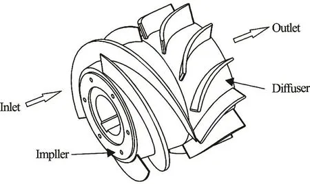
Fig.1 Compression cell of the multiphase pump
The main geometry parameters of the multiphase pump impeller include the shroud diametertD, the inlet hub diameter1hd , the outlet hub diameter2hd ,the impeller axial length H, the inlet hub-shroud ratiotrh, the half cone angle of the hub γ, the shroud leading blade angle1yβ, the shroud trailing blade angle2yβ, the blade number Z, the blade spacing t, the blade airfoil expansion length l, the blade lead S, and the maximum blade thickness δ.These parameters are not isolated but correlated with each other. The structural diagrams of the impeller and the blade airfoil are shown in Fig.2 and Fig.3,respectively. A reasonable structure of the impeller and the airfoil can prevent the separation of the gas and the liquid, as is necessary for the gas-liquid two-phase transportation. The differential pressure between the inlet and the outlet of the pump and the inhibition of the separation of the gas phase and the liquid phase are considered when selecting the geometry parameters.
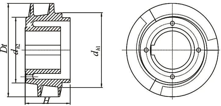
Fig.2 The structure of the impeller of the multiphase pump
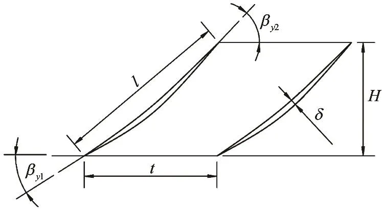
Fig.3 The unfolded blade airfoil of the multiphase pump
2. Quasi-3D hydraulic design method
The hydraulic design method is the key to obtain an optimal geometry structure of the impeller of the RMMP. Peng et al.[20]and Luo et al.[21]designed a Francis runner and a Kaplan turbine runner by the Q3DHD method. In this study, the Q3DHD method based on the1S and2S stream surfaces is used to design the impeller and to calculate the flow field of the designed impeller during the optimization progress.In the Q3DHD method, the 3-D space flow field and the final blade are obtained by a repeated iteration of both the flow fields on1S and the average2S stream surface. The average2S stream surface is the middle flow surface. The1S stream surfaces are a series of revolution surfaces rotated by the streamlines on the average2S stream surface.
At the beginning of the hydraulic design, the initial geometry structure of the impeller designed by the method proposed in Ref.[5] is obtained. Based on the initial impeller, the initial1S and the average2S stream surfaces are obtained. Then, the initial impeller is iteratively calculated by the quasi-3D flow calculation. At the beginning of the iteration,1S stream surfaces are conformally transformed and then its flow field is numerically calculated by using the finite element method. After that, an average2S stream surface is rebuilt by the intermediate streamline method based on the calculation results of1S stream surfaces. Then, the flow field of the average2S stream surface is numerically calculated with a quasiorthogonal method. Then new1S stream surfaces are rebuilt based on the new flow net. In this cycle, the iterative calculation is carried out between1S and average2S stream surfaces until the condition of convergence is satisfied. Finally, the impeller is built after drawing the blade with reasonable velocity moment distribution, blade thickening and leading edge smoothing.
3. The calculation method of BVF on blade surface
The common formula to obtain the BVF value is
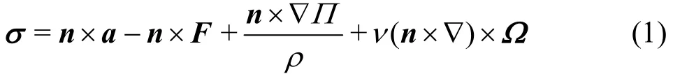
where σ represents the value of the BVF, n is the unit vector of the outside normal, Ω is the vorticity,Ω = ▽×V , a is the fl uid acceleration, F is the body force, ∏ is the normal stress consisting of the pressure p and a viscous-dilatation term.
The boundary vortex flux σ is the cause of vorticity and diffusion. It is mainly composed of four components: (1)aσ, generated by the acceleration on walls, (2)Fσ, generated by the body force, (3)pσ,generated by the pressure gradient p▽ on walls, and(4)τσ, generated by the shear stress τ on walls.These four parts can be evaluated by the following equations:
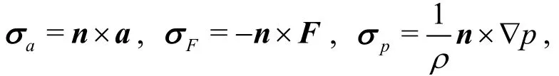

where ν is the dynamic viscosity.
The speed of the impeller can be considered as a constant when the multiphase pump is operated at a steady state, i.e., σa=0, and the body force is ignored, i.e., σF=0. Due to the large Reynolds number, the influence of σpis much greater than τσ, generated by the viscosity. Thus,τσ can be ignored. The undesirable distribution of the boundary vortex flux on the blade surfaces can cause the boundary layer separation and the secondary flow,which will subsequently affect the hydraulic performance and the stability of the pump. If the boundary vorticity distribution on the blade surfaces can be controlled effectively, the optimization design can be achieved.
Assuming that the rotation velocity around -Z axis is ω, and the required torque is M. Then, the power per unit time that the impeller applies to the liquid is P = M · ω = Mzω . In the cylindrical coordinates (,,)rzθ, we have the following relationship
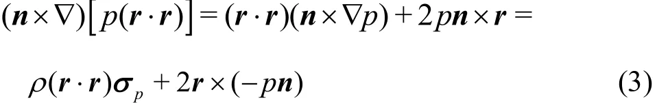
The axial torque generated by the pressure on the blade surfaces can be expressed as
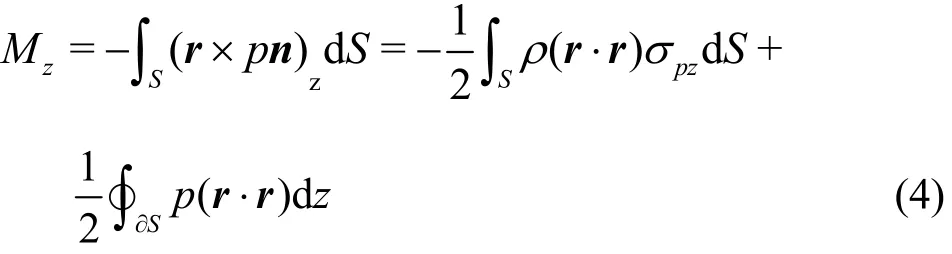
where zM is the axial torque, S is the area of the blade surface, S? is the boundary of the blade surface, andpzσ is the axial component ofpσ.
From Eq.(4), it can be seen thatpzσ contributes the most work. Therefore, in the analysis of the boundary vortex flux distribution on the blade surfaces, one may only considerpzσ. In the Cartesian coordinates,pσ is
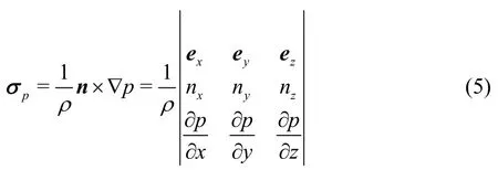
The axial component ofpσ is
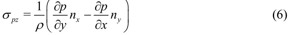
From the above formula, it can be seen that the pressure distribution on the blade surfaces is required in the BVF diagnose. The velocity distributions are obtained after the Q3DHD for the impeller. Based on the relative flow Bernoulli equation, the pressure distributions at each point can be obtained.
For the impeller, the capacity for work is mainly determined by σpz=σp·ez. In the orthogonal coordinates, the valuepzσ can be calculated by the following equation
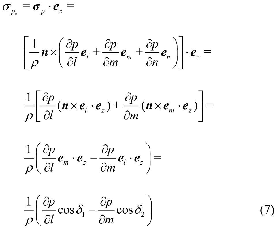
where δ1is the angle between the cross-section line of the flow direction and the Z-axis, δ2is the angle between the flow line and the Z-axis, ?p/?l is the pressure gradient along the flow line direction,?p/?m is the pressure gradient along the crosssection of the flow direction.
In addition, the pressure at each point can be calculated by the spline interpolation method or the finite difference method.
4. Optimization ideas
The design defects can be discovered correctly according to the BVF diagnosis of the blade surfaces.However, the modification of the parameters of the impeller depends on experiences, which means that the optimization design involves repeated adjustments.Therefore, it is necessary to construct an optimization model based on the BVF diagnosis with some autooptimization design methods.
This paper proposes a comprehensive impeller optimization design method based on the Q3DHD, the BVF diagnosis and the GA. The flow field distribution in the impeller channel can be obtained using the Q3DHD method, the BVF distribution on the blade surface can be obtained based on the flow field data,and the optimization model is built according to the hydraulic design characteristics of the multiphase pump.
4.1 Optimization variables
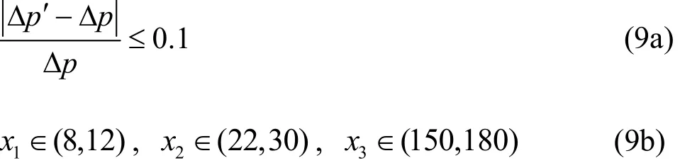
Among the parameters of the multiphase pump impeller, the shroud diameter Dtis determined by the head coefficient and the flow coefficient in the initial design. The inlet hub-shroud ratio htris determined by the flow rate. The inlet hub diameter dh1is determined by htr. The hub half cone angle γ determines the size of the outlet diameter of the hub dh2. The leading blade angle βy1and the trailing blade angle βy2have significant influences on the differential pressure of the impeller. The blade number Z has a direct relation with the blade wrap angle θ. Therefore, βy1, βy2and θ, expressed by x1, x2and x3, are chosen as the optimization variables in this study.
4.2 Objective function and constraints
Reference [22] shows that the more uniform the BVF distribution, the better the hydraulic performance of the impeller. Therefore, the uniform rate of the BVF is chosen as one indicator of the objective function in this optimization design method and it is shown as:
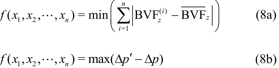
In the optimization calculation process, the differential pressure should conform to the design requirements under a given flow condition. The range of optimization variables and the differential pressure are chosen as the constraints.
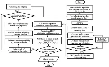
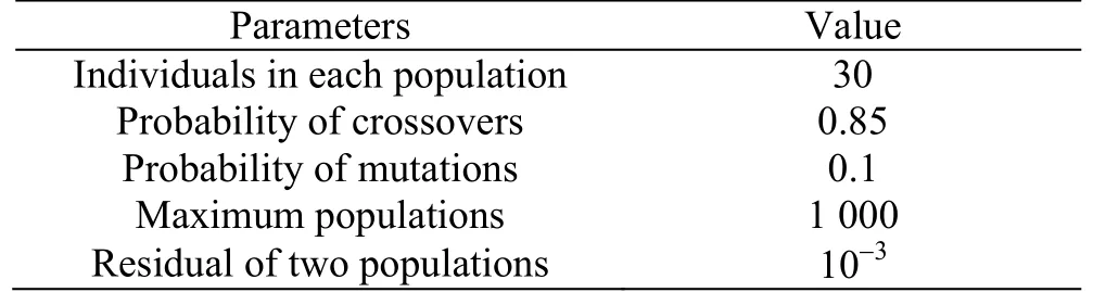
Table 1 Operating parameters in the optimization of RMMP impeller
4.3 Procedure of the optimization
Based on the optimization model stated above,an impeller optimization design program is developed by combining the BVF diagnosis, the GA and the Q3DHD for the impeller. During the optimization design, the initial impeller is determined by the 2-D theory. The data of the inviscid flow field in the process of the Q3DHD is used for BVF diagnosis evaluation. With the GA optimization, the design parameters are obtained by a random global search and the optimal combination. The method is implemented in the program to achieve the optimization design for an impeller of the RMMP.
In the hydraulic design optimization program, the binary gray code is used in the GA optimization part to normalize the three optimization variables. The respective bit gray code is adopted for the numerical accuracy requirement of each parameter. At the beginning of the optimization, the initial chromosome population N is randomly generated in the optimization variable space and the initial meridional passages are subsequently generated by the hydraulic design method of the 2-D theory. Based on the initial meridional passage, a series of1S stream surfaces and an average2S stream surface for each chromosome are obtained. After the repeated iteration of1S and average2S stream surfaces, the iteration stops when the convergence condition is satisfied. Based on the final1S and average2S stream surfaces, a blade of the impeller of each chromosome can be formed by drawing the blade camber line and thickening the blade. Then the Q3DHD for the impeller of each chromosome is completed by using the quasi-3D flow theory. After that, the pressure and BVF distributions on blade surfaces are determined according to Eq.(6)with the velocity data obtained during the Q3DHD.Furthermore, the objective function values, namely the fitness values of each chromosome, are obtained.Based on the fitness values, the chromosomes are ranked and chosen to make pairs, crossovers and mutations. Then, the new offspring chromosomes are generated. The above description is the first evolutionary process. This process will be iterated continually. With the iteration of the program, the quality of the population will be improved until meeting the convergence criteria or reaching the maximum num-in the optimization process are shown in Table 1.ber of iterations. Finally, the maximum fitness value,selected as the optimal solution, is obtained as the final generation. The flowchart of the optimization program is shown in Fig.4. The operation parameters
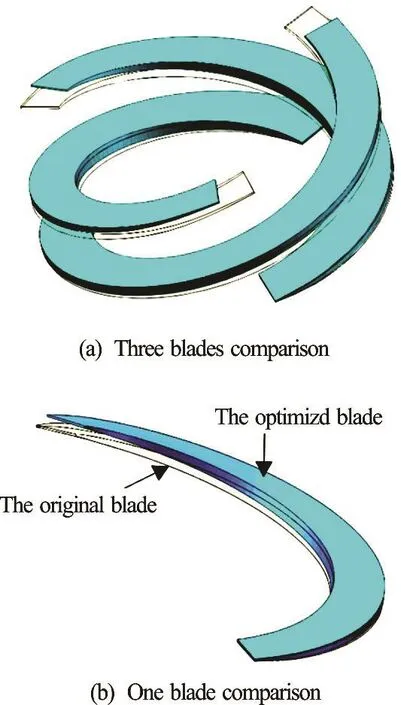
Fig.5 (Color online) Comparison of the impellers before and after optimization
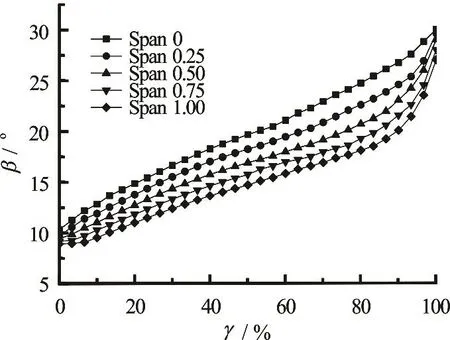
Fig.6 Blade angle variations along the meridional streamline of the original blade

Fig.7 Blade angle variations along the meridional streamline of the optimized blade
5. Comparison between the original and the optimized impellers
In order to test the feasibility of the optimization method presented above, the flow fields and the hydraulic performances of the impeller designed only by the Q3DHD method and the impeller optimized using the above method are compared.
5.1 Comparison of geometry structures
Figure 5 shows the comparison of the geometry structures before and after the optimization. It can be seen that the wrap angle of the optimized impeller is smaller than that of the original impeller. The detailed comparisons of the blade angles for different blade heights are shown in Fig.6 and Fig.7, in which the horizontal axis γ and the vertical axis β are the percentage of the chord length from the leading edge to the trailing edge and the relative flow angle,respectively.
Figure 6 shows the variations of the blade angle of the original impeller designed only by the Q3DHD method along the meridional streamlines for different blade heights and spans 0, 0.25, 0.50, 0.70 and 1.00 from the hub to the shroud. Figure 7 shows the results at the corresponding positions of the optimized impeller.
By comparing Fig.6 and Fig.7, one can see that the five streamlines of the initial impeller have similar leading blade angles and the similar trailing blade angles, while those of the optimized impeller have very different leading blade angles and trailing blade angles.
5.2 Comparison of internal flow fields
A compression cell flow field, along with the added front extension and backward extension, is the entire region for the flow field numerical simulation.The geometry models of the calculation domain of the original and the optimal impellers are similar, as shown in Fig.8.
The structured grids are generated for the established models. The topology is used to approximate the geometric model, and then the hexahedral grid is generated on the topology. The original impeller has a similar grid as that of the optimized impeller, as shown in Fig.9.
The RANS equations are used in the numerical simulation of the flow field. The RNG k-ε turbulence model is selected to close the Reynolds averaged equations. The finite volume method is applied to discrete these control equations. For the pressure terms,the second order central difference scheme is adopted,while for the items of the speed, the turbulent kinetic energy and the turbulent dissipation rate, the second order upwind difference scheme is adopted. The SIMPLEC algorithm is applied for the coupling solution of the pressure and the velocity. The underrelaxation iterative is adopted in the iterative calculation with coefficients of 0.3 for the pressure term, 0.7 for the speed term and 0.8 for the turbulent kinetic energy and the turbulent dissipation rate.
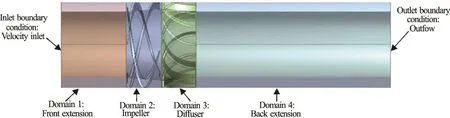
Fig.8 (Color online) Geometry model of calculation domain
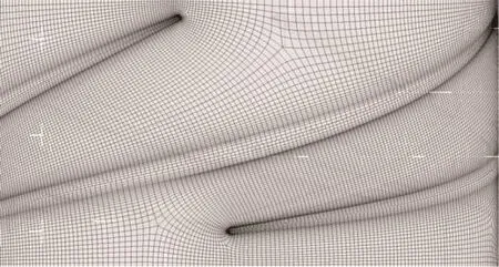
Fig.9 Grid of original impeller
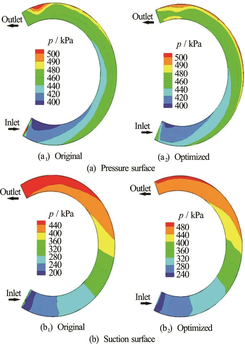
Fig.10 (Color online) Static pressure distributions on blade surfaces
The mixture of the air and the water is selected as the media in the flow field. A buffer tank is set in front of the multiphase pump to ensure uniform mixing of the gas and the liquid. Therefore, the flow in the entrance of the multiphase pump is supposed to be in the bubbly flow pattern. The Eulerian-Eulerian two-phase model is used in calculating the multiphase flow. The gas-liquid two-phase is considered as the full continuum in the entire flow field. With the above hypothesis, the following boundary conditions are adopted:
(1) Inlet condition
Due to the assumption of the bubbly flow, the inlet gas volume fraction (IGVF) can be considered as uniformly distributed. Thus, the inlet velocities of the gas and the liquid are equal and can be calculated by the following formula
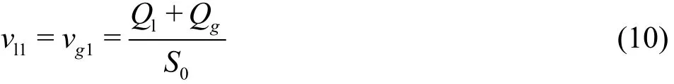
wheregQ is the flow rate of the gas,lQ is the flow rate of the liquid,0S is the inlet cross-sectional area.
The turbulent kinetic energy k and the turbulent energy dissipation rate ε at the entrance can be calculated by the empirical formulas:
The average diameter of the gas bubbles at the entrance is set as that used in Ref.[23].
(2) Outlet condition
Due to the enough backward extension, the full developed flow condition is used in the outlet section,which is shown as
(3) Wall conditions
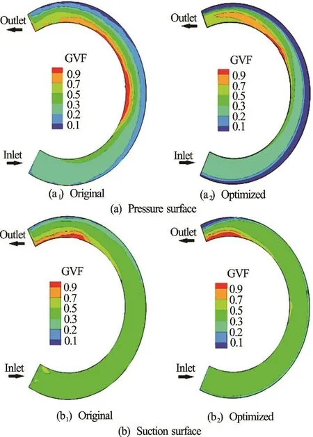
Fig.11 (Color online) Distributions of GVF on blade surfaces
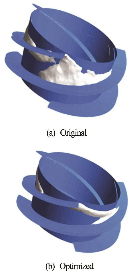
Fig.12 (Color online) Distribution of gas pockets in both impellers
The no-slip condition of the viscous fluid is used in calculating the gas and liquid velocities on the walls,meaning that the wall velocities are zero. In the region near the wall, the gas and the liquid phases are treated with the standard wall function.
The pressure satisfies the Neumann condition in the boundary of the calculation region. In order to ensure the stability of the calculation, a point is regarded as a reference for the pressure in the calculation region and its value is 101 325 Pa. The pressures calculated at other points are the relative value of the reference pressure.
Both the numerical simulations of the original impeller and the optimized impeller are carried out by the CFD software ANSYS-FLUENT 14.0. The parameters employed here are listed as follows: the speed is 4 500 rpm, the IGVF is 30% and the mixture total flow is 75 m3/h. Then both the flow fields of the original impeller and the optimized one are compared.
5.2.1 Comparison of static pressure distributions
The static pressure distributions on the blade surfaces of the two impellers are shown in Fig.10. It can be seen that the static pressure on the blade surfaces of the two impellers gradually increases from the inlet to the outlet. The pressure near the outlet part on the pressure surface of the optimized impeller is distributed more uniformly than that of the original one. However, the pressure distributions on the suction surfaces of both impellers are similar.
5.2.2 Comparison of gas volume fraction (GVF) distributions
Figure 11 shows the GVF distributions on the blade surfaces of the original impeller and the optimized one. It is clear that the GVF distributions of the two impellers are similar: The GVF increases near the hub but decreases near the shroud, and there are gas pockets near the hub of the impeller, caused by the centrifugal force, which moves the liquid to the shroud and the gas to the hub. However, the levels of the gas-liquid separation are different for both impellers. Here, the region whose GVF is larger than 0.85 is called the gas pocket. For the original impeller,the gas pockets distribute from the 2/5 chord to the 4/5 chord on the pressure surface. But, the number of the gas pockets decreases. And they only distribute at the 4/5 chord on the pressure surface of the optimized impeller. For the two suction surfaces, the gas pockets can only be found in the outlet part. The scale of the gas pocket is smaller on the suction of the optimized impeller than that of the original impeller. The white regions in Fig.12 show the gas pockets in the two impellers. It is clear that the scale of the gas pocket is decreased remarkably for the optimized impeller,compared with the original impeller. That is to say,the high GVF area is significantly reduced in the optimized impeller.
5.2.3 Comparison of vectors of relative velocity
The above analysis shows that the flow fields on both pressure surfaces are significantly different. Here,the vectors of the relative velocity on the pressure surfaces of both impellers are shown in Fig.13.
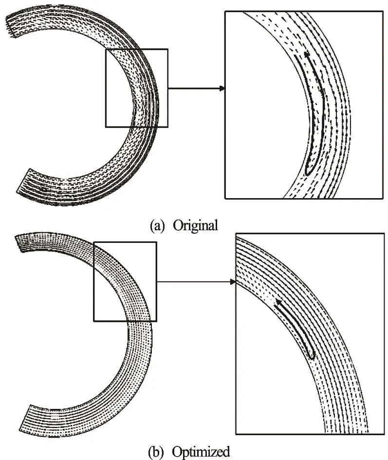
Fig.13 Vectors of relative velocity on pressure surfaces
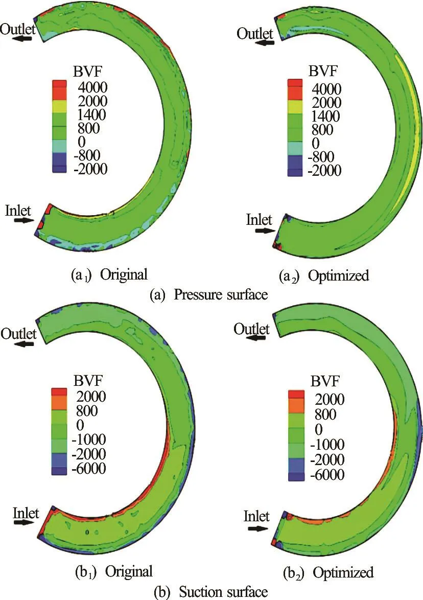
Fig.14 (Color online) Comparison of BVF distributions on the blade surfaces
From the vectors of the relative velocity shown in Fig.13, it can be seen that a big vortex is found near the hub of the original impeller. Actually, the vortex exactly locates in the gas pocket shown in Fig.10. For the optimized impeller, the vortex near the hub is obviously shrunk.
5.2.4 Comparison of BVF distributions
Based on the flow field results calculated by the CFD and the BVF on the blade surfaces, the axial componentpzσ can be obtained. The BVF distributions on the blade surfaces of the two impellers under the design working condition are shown in Fig.14.There are some peak zones forpzσ near the shroud on the blade surfaces of the original impeller. These peak zones will induce the boundary layer separation and the secondary flow, which will subsequently reduce the flow quality and the hydraulic performance.On the contrary, the distribution ofpzσ on the surfaces of the optimized impeller blade is uniform except for some small peak zones. Obviously, the BVF distributions on the blades of the optimized impeller are significantly improved as compared with those on the original impeller blades.
5.3 Comparison of hydraulic performances
5.3.1 Introduction of test bench
The test bench of the multiphase pump is composed of a gas loop and a liquid loop. In the test process, the compressed air is provided by the compressor while the circulation water of the liquid line is provided by the pump. The gas and the liquid are mixed uniformly in a buffer tank to form a homogeneous gas-liquid multiphase fluid. The mixture flows out of the buffer tank, and then enters the multiphase pump to be pressurized. Finally, the multiphase fluid flows into the open tank, where the gas and the liquid are separated through the outlet line. The schematic diagram of the test bench is shown in Fig.15. The parameters measured in this test include the flow rates of the water and the air, the pressure at the inlet and the outlet of the RMMP, the speed n, and the torque of the rotation axis. The LDBE-80 electromagnetic flow meter is employed to measure the liquid flow rate. The turbine meter of the LWQ-50 series is selected to measure the gas flow rate. Two pressure transmitters of the 1 151 series are selected to measure the pressure at the inlet and the outlet of the RMMP. In addition, a torque meter is adopted to measure the torque of the rotation axis. Table 2 presents the details of the measuring devices and their uncertainty levels.
5.3.2 Comparison of hydraulic performances
Figure 16 shows the differential pressure between the inlet and the outlet of the pump and the efficiency of the two impellers against the gas-liquid mixture total flow rate. The hydraulic performance of the optimized impeller is significantly improved because for the optimized impeller, the gas-liquid separation is reduced, with a higher energy provided subsequently.The original impeller reaches the maximum efficiency at the point with the gas-liquid flow rate of 75 m3/h,while the optimized impeller does that at 85 m3/h. The differential pressure and the maximum efficiency increase by about 4% and 2.5%, respectively. Additionally, the region of high efficiency is dramatically wider for the optimized impeller. Therefore, it may be concluded that the optimization method presented in this paper is reliable.
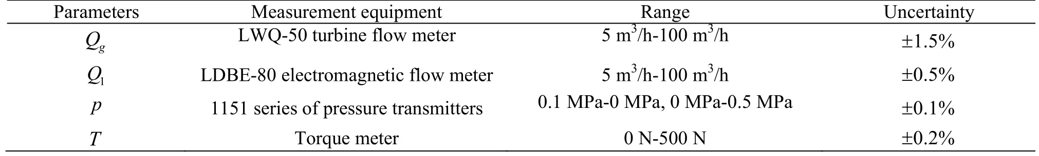
Table 2 Details of the various pieces of the measuring devices
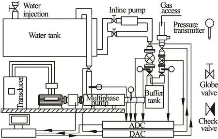
Fig.15 Schematic diagram of the test bench for the multiphase pump
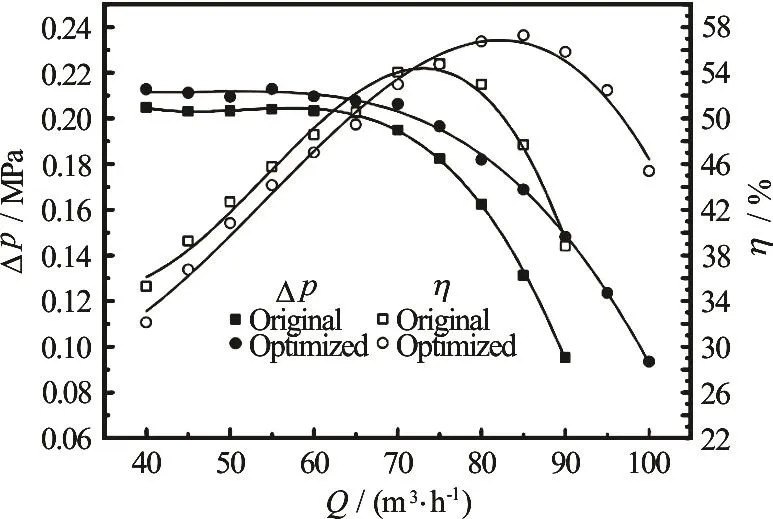
Fig.16 Comparison of hydraulic performances (IGVF=30%)
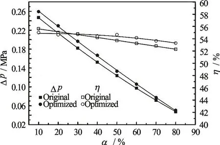
Fig.17 Performance against IGVF (Total flow rate Qtot=75m3/h)
Figure 17 shows the performance curves of the two RMMPs with the IGVF when the total flow rate is 75 m3/h. The horizontal axis α is the IGVF in Fig.17. It can be seen that the differential pressure declines with the increase of the IGVF. However, the efficiencies of both RMMPs only see a slight decline with the increase of the IGVF. For the two RMMPs,the differential pressures of the optimized RMMP are always higher than those of the original RMMP.However, the efficiency of the optimized RMMP drops slower than the original RMMP.
6. Conclusion
In the traditional optimization design method based on the GA, the CFD method is usually used to evaluate the objective functions. Repeated geometry structure rebuilding and re-gridding are required,which involves a large amount of CFD calculations, a long optimization time and a high demand on the hardware devices. In this paper, an optimization design method combining the Q3DHD, the BVF diagnosis and the GA is proposed, with the BVF diagnosis based on the Q3DHD being used to evaluate the objection function. It is regarded as the evaluation method of the fitness value in the GA. The CFD analysis and the hydraulic performance tests are conducted to compare the impeller designed only by the Q3DHD and the optimized impeller. In the flow field, the pressure distribution of the optimized impeller is more reasonable and the gas-liquid separation is significantly inhibited. Furthermore, in the optimized impeller, one sees no local unevenness of the BVF distribution near the shroud, as would be found in the original impeller. The hydraulic performance test shows that the differential pressure and the maximum efficiency of the optimized impeller are increased by 4% and 2.5%, respectively. The region of high efficiency is dramatically wider for the optimized impeller. Overall, from the aspects of either improving the distribution of the internal flow field or enhancing the hydraulic performance, the optimization method performs well. In addition, the proposed optimization method is applicable not only for the multiphase pump impeller, but also for other types of impellers.
Acknowledgement
This work was supported by the High Technology ship Research of Ministry of Industry and Information Technology (Grant No. [2014]503).
[1] Kuchpil C., Souza C. E. M., Coelho E. J. J. et al.Barracuda subsea helico-axial multiphase pump project [C].Offshore Technology Conference. Houston, USA, 2013,OTC 24217.
[2] Samsudin Z. B., Ajmi S. M., Qudaihy D. S. et al. Production enhancement using a multiphase helico-axial pump in a remote hilly-terrain oil field in Saudi Arabia [C]. SPE Saudi Arabia Section Technical Symposium and Exhibition. Al-Khobar, Saudi Arabia, 2012, SPE 160850.
[3] Zhu H., Li Z., Li Q. Discussion on design of flow parameters of helico-axial multiphase pump [J]. Journal of Engineering Thermophysics, 2005, 26(6): 954-956(in Chinese).
[4] Cao S., Peng G., Yu Z. Hydrodynamic Design of rotodynamic pump impeller for multiphase pumping by combined approach of inverse design and CFD analysis[J], Journal of Fluids Engineering, 2005, 127(2): 330-338.[5] Zhang Y., Zhang J., Zhu H. et al. 3D blade hydraulic design method of the rotodynamic multiphase pump impeller and performance research [J]. Advances in Mechanical Engineering, 2014, 803972.
[6] Kim J., Lee H., Kim J. et al. Improvement of hydrodynamic performance of a multiphase pump using design of experiment techniques [J]. Journal of Fluids Engineering,2015, 137(8): 081301.
[7] Liu X., Luo Y., Karney B. W. et al. A selected literature review of efficiency improvements in hydraulic turbines[J]. Renewable and Sustainable Energy Reviews, 2015, 51:18-28.
[8] Liu X., Zhang W. Multi-objective automatic optimization design of centrifugal impeller based on genetic algorithm[J]. Journal of Xi’an Jiaotong University, 2010, 44(1):31-35(in Chinese).
[9] Zhang J., Zhu H., Yang C. et al. Multi-objective shape optimization of helico-axial multiphase pump impeller based on NSGA-II and ANN [J]. Energy Conversion and Management, 2011, 52(1): 538-546.
[10] Lee Y. T., Ahuja V., Hosangadi A. et al. Shape optimization of a multi-element foil using an evolutionary algorithm [J]. Journal of Fluids Engineering, 2010, 132(5):051401.
[11] Djavareshkian M. H., Latifi A. Optimization of wind turbine airfoil with good stall characteristics by genetic algorithm using CFD and neural network [C]. ASME 2013 International Mechanical Engineering Congress and Exposition. San Diego, USA, 2013, IMECE2013-64598.
[12] Goto A., Nohmi M., Saurai T. et al. Hydrodynamic design system for pumps based on 3-D CAD, CFD, and inverse design method [J]. Journal of Fluids Engineering, 2002,124(2): 329-335.
[13] Alfaro-Ayala J. A., Ayala-Ramírez V., Gallegos-Mu?oz A.et al. Optimal location of axial impellers in a stirred tank applying evolutionary programing and CFD [J]. Chemical Engineering Research and Design, 2015, 100: 203-211.
[14] Derakhshan S., Pourmahdavi M., Abdolahnejad E. et al.Numerical shape optimization of a centrifugal pump impeller using artificial bee colony algorithm [J]. Computers and Fluids, 2013, 81(7): 145-151.
[15] ?idonis A., Panagiotopoulos A., Aggidis George A. et al.Parametric optimisation of two Pelton turbine runner designs using CFD [J]. Journal of Hydrodynamics, 2015,27(3): 403-412.
[16] Wu J., Wu J. Boundary vorticity dynamics since Lighthill’s 1963 Article: Review and development [J]. Theoretical and Computational Fluid Dynamics, 1998, 10(1-4):459-474.
[17] Zhang Y., Luo X., Ding H. et al. Design optimization of the impeller for a high specific-speed pump based on BVF diagnosis [J]. Journal of Engineering Thermophysics,2010, 31(5): 765-768(in Chinese).
[18] Li Z., Wang L., Dai W. et al. Diagnostics of a centrifugal pump during starting period based on vorticity dynamics[J]. Journal of Engineering Thermophysics, 2010, 31(1):48-51(in Chinese).
[19] Zhou X., Zhang Y., Ji Z. et al. The impeller improvement of the centrifugal pump based on BVF diagnostic method[J]. Advances in Mechanical Engineering, 2014, 464363.
[20] Peng G., Luo X., Guo Q. et al. A quasi three-dimensional inverse method for kaplan turbine runner in rotational flow [J]. Journal of Hydraulic Engineering, 1996, (10):10-17(in Chinese).
[21] Luo X., Chen N., Lin R. A quasi-three dimensional design method for Francis runner [J]. Journal of Hydraulic Engineering, 1996, (10): 18-21(in Chinese).
[22] Zhou X., Zhang Y., Ji Z. et al. The optimal hydraulic design of centrifugal impeller using genetic algorithm with BVF [J]. International Journal of Rotating Machinery,2014, 845302.
[23] Zhang J., Cai S., Zhu H. et al. Experimental investigation of the flow at the entrance of a rotodynamic multiphase pump by visualization [J]. Journal of Petroleum Science and Engineering, 2015, 126: 254-261.
- 水動力學研究與進展 B輯的其它文章
- Editorial Message
- ICHD’ 2018 The 13th International Conference on Hydrodynamics First Announcement September 2-6, 2018 Sheraton Grand Inchecon Hotel Songdo, Incheon Korea
- Compressible effect on the cavitating flow: A numeric study *
- Design and experiment of the centrifugal pump impellers with twisted inlet vice blades *
- Two timescales for longitudinal dispersion in a laminar open-channel flow *
- Numerical simulation of a two-dimensional flapping wing in advanced mode *