
Time-domain modeling of a cutter exiting a workpiece in the slot milling process
2016-11-23 01:58:24LuoMingMeiJiweiZhngDinghu
CHINESE JOURNAL OF AERONAUTICS 2016年6期
Luo Ming,Mei Jiwei,Zhng Dinghu
aKey Laboratory of Contemporary Design and Integrated Manufacturing Technology,Ministry of Education,Northwestern Polytechnical University,Xi’an 710072,China
bMachining and Condition Monitoring Group,Faculty of Engineering,University of Nottingham,NG7 2RD,UK
Time-domain modeling of a cutter exiting a workpiece in the slot milling process
Luo Minga,*,Mei Jiaweia,b,Zhang Dinghuaa
aKey Laboratory of Contemporary Design and Integrated Manufacturing Technology,Ministry of Education,Northwestern Polytechnical University,Xi’an 710072,China
bMachining and Condition Monitoring Group,Faculty of Engineering,University of Nottingham,NG7 2RD,UK
In a milling operation,there must be processes of a cutter entering and exiting the workpiece boundary.The cutter exit is usually in the feed direction and the dynamic response is different from that in the normal cutting process.This paper presents a new time-domain modeling of mechanics and dynamics of the cutter exit process for the slot milling process.The cutter is assumed to exit the workpiece for the first time with one tooth right in the feed direction.The dynamic chip thickness is summed up along the feed direction and compared with the remaining workpiece length in the feed direction to judge whether the cutter is ready to exit the workpiece or not.The developed model is then used for analyzing the cutting force and machining vibration in the cutter exit process.The developed mathematical model is experimentally validated by comparing the simulated forces and vibrations against the measured data collected from real slotting milling tests.The study shows that stable cutting parameters cannot guarantee stable cutting in a cutter exit process and further study can be performed to control the vibration amplitude in this specific process.
1.Introduction
In a milling operation,there are frequent cutter entrances into and exits from a workpiece,the two most common processes in a milling operation.While extensive research has been done in the normal milling process,1there have been few concerns about the cutter exit process.In practical machining,manufacturers often observe vibration marks left on a machined surface where a cutter exits a workpiece,but the underneath physics is still not clear and corresponding control methods are yet to be developed.
Vibrations happening in a milling operation lead to many negative influences such as poor surface finish,unacceptable machining accuracy,an accelerated tool wear rate,and lower machining productivity.These phenomena will result in low part surface integrity of high value-added components,such as aero-engine blisks or casings.Chatter vibration,which is the most common form of vibration,2often occurs because of the interaction between a workpiece and a milling cutter.3,4Since its first identification and study by Taylor5,much research work has been done on chatter.Tobias6presented the first accurate model to describe self-excited vibrations in orthogonal cutting.Minis et al.7,8used the Nyquist criterion to solve the milling stability numerically.Altintas and Budak9developed an analytical solution in frequency domain to predict stability lobes,which was proven to be an effective method by experiments.10Insperger and Stepan11presented a semidiscretization(SD)method and solved the stability boundary problem in discrete time domain.Meng et al.12developed a novel criteria of stability analysis for a single degree offreedom(DOF)based on the approximately periodic property of the time delay in a turning process and the delay decomposition method.Ding et al.13,14developed a numerical integration method for milling stability prediction.In the above analysis,prediction of the dynamic chip thickness is one of the most important issues,and different chip thickness calculation methods including circular path15and cutter runout16have been developed.However,the presented research mostly focused on the normal cutting process;dynamic chip thickness calculation for the cutter exit process and vibration analysis is scarce.
As for cutter exits,published research has shown that they have great effects on burr forming.17,18Toh19studied the effects of entrance and exit of a cutter at a corner in the tool path planningstage.Theseresearch worksnevertheless focused only on burr forming or its controlling rather than the dynamic response.Wanner et al.20studied the exit and post-exit behavior and dynamics of a cutter in milling of a thin-walled workpiece.Their research results show that a small change in the exit angle may result in a considerable improvement in the cutting behavior.Zhang et al.21included both the periodical excitation and the regenerative excitation in the stability analysis for milling of a thin-walled workpiece,and an effective cutting parameter optimization method was developed to assure surface location accuracy.However,the above studies mainly focused on a cutter exiting a workpiece in one revolution during a milling process,not the final exit from the workpiece.The mechanics of the cutter exit is quite different from that in the normal cutting process.
Although extensive research has been done in the normal milling process,publications on milling force modeling in the cutter exit process are scarce.This paper provides new ideas in this field.In this paper,a model for the cutter exit process from a workpiece is presented based on the regenerative chatter model.9Firstly,an analytical model for this specific process is introduced to estimate the exit time at a certain rotation angle.Next,the chip thickness,which has a significant effect on the dynamic milling process,is updated through the computational method depending on the exit time.The actual chip thickness is then used to analyze the cutting force and vibration during the cutter exit process.Finally,cutting experiments are carried out to validate the developed model.
2.Cutter exit process analysis
A 2-DOF milling system is shown in Fig.1,which can be described by the model developed by Altintas et al.22,and it can be represented by two orthogonal degrees offreedom in the X and Y directions as
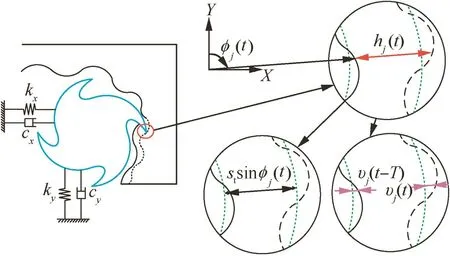
Fig.1 Dynamic chip thickness of a 2-DOF milling system.
where m,c,and k are the mass,structural damping ratio,and stiffness,respectively.While the circular tool path assumption with a low feedrate per tooth is used,the model indicates that the cutting tooth leaves a wavy surface because of the vibration between the cutter and the workpiece.When the next tooth begins cutting,it removes the wavy surface left by the previous tooth and generates a new wavy surface.Thus,the total chip thickness consists of three parts,which can be described by the following equation in terms of the static chip thickness,the vibration by the current tooth,and the vibration by the previous tooth:

where strepresents the feedrate per tooth,and υj(t)and υj(t-T)represent the dynamic displacements generated by the vibrations caused by the current and previous tooth passes at the angular position φj(t),respectively.
However,when the cutter is about to exit the workpiece,the remaining workpiece length in the feed direction becomes shorter.Thus,hj(t)may be larger than the remaining workpiece length in the feed direction,and hence Eq.(2)is no longer appropriate in calculating the chip thickness.Therefore,a new model should be developed for analyzing this specific process.Since the cutter exit process is still a dynamic process,the dynamic chip thickness expressed by Eq.(2)can be used as the basis for analyzing the chip thickness during the cutter exit process.
As υj(t-T)represents the vibration caused by the previous tooth,it has left a wavy surface on the workpiece.When the current tooth rotates to the angular position φj(t),the wavy surface left by the previous tooth is already known.Hence,only stsin φj(t)and υj(t)will affect the chip thickness of the current tooth.When the cutter is about to exit the workpiece,the remaining thickness in the feed direction directly affects the current chip thickness.Therefore,the cases when the cutter is going to exit the workpiece should be analyzed first.
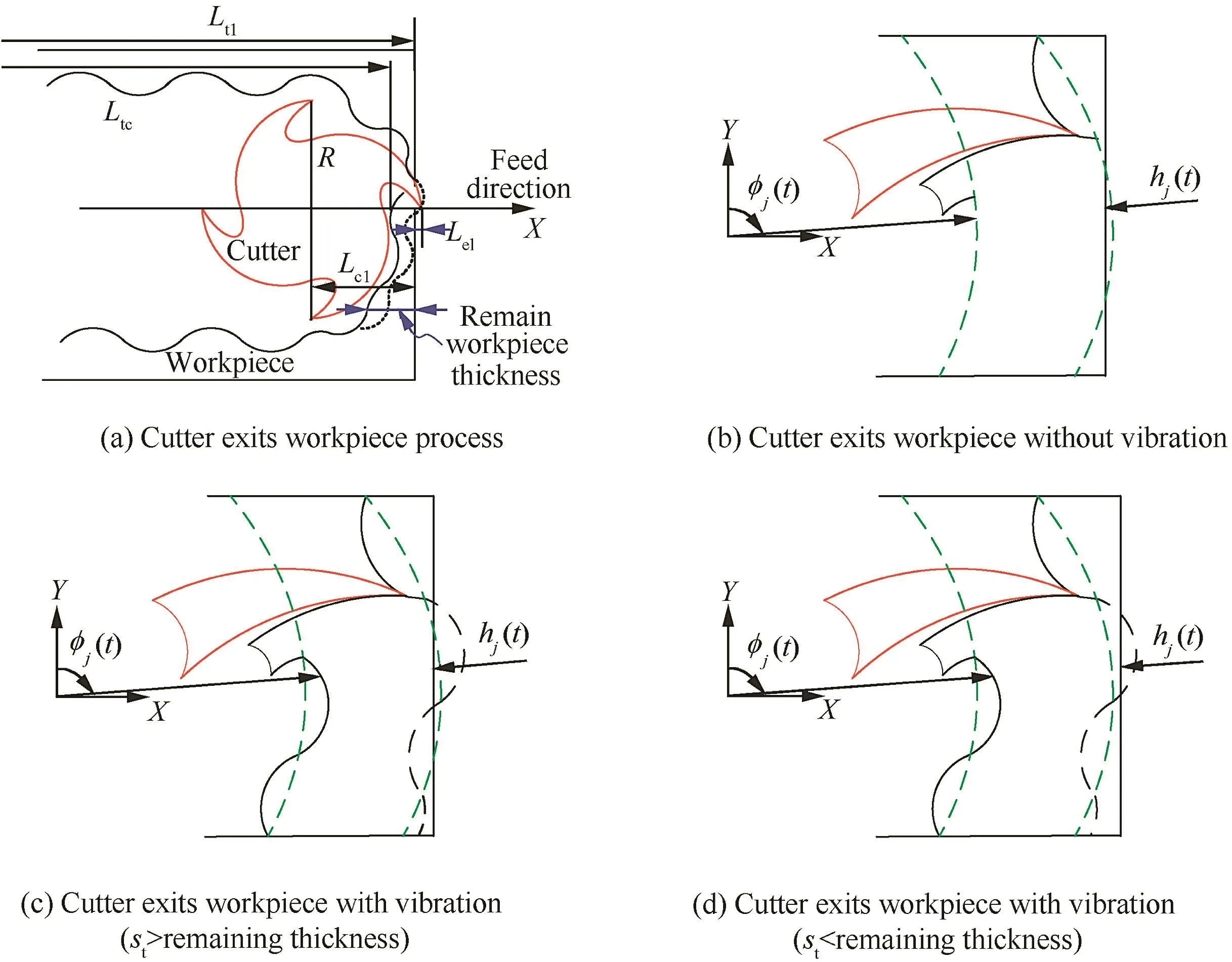
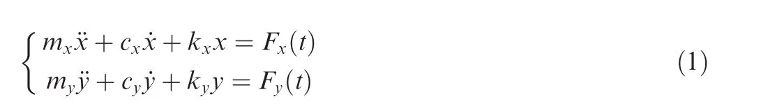
Fig.2 Cases of the cutter exits the workpiece.
As shown in Fig.2,there are three possible cases for the cutter to exit the workpiece.In Fig.2(b),when stsinφj(t)-υj(t-T)is larger than the remaining workpiece thickness in the feed direction and no vibration occurs,the cutter exits the workpiece along the feed direction.In this case,the feedrate has an important effect on the chip thickness.If vibration occurs in the case shown in Fig.2(c),the chip thickness is determined by the previously left wavy surface and the feedrate per tooth,as well as the current tooth vibration.Besides,the cutter tooth may exit the workpiece due to the existence of vibration while the feedrate does not make the cutter move outside the boundary of the workpiece,as shown in Fig.2(d).In all the three cases,the chip thickness calculated by Eq.(2)is larger than the remaining workpiece thickness in the feed direction and cannot be used directly for the cutting process analysis.For all the cases,the tooth is nearest to the workpiece boundary in the feed direction.Therefore,the assumption that the cutter exits the workpiece along the feed direction for the first time is reasonable.
3.Analytical modeling of the cutter exit process
3.1.Undeformed chip thickness calculation
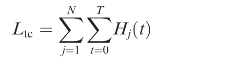
To decide whether the current tooth exits the workpiece or not,let us assume that for a milling operation,the cutter starts to exit the workpiece in the feed direction in the slot milling process,that is,when the rotation angle of the current tooth is 90°.As shown in Fig.2(a),the current tooth is going to exit the workpiece in the X direction,which is the feed direction.
Summing the chip thickness for all the teeth in the feed direction from the start of cutting to the current time,we get the total removed material length in the feed direction.If the accumulated total chip thickness satisfies the following equation,it means that the cutter is going to exit workpiece for the first time in the feed direction.

where Ltlis the length of the workpiece,while Ltcis the summation of the chip thickness for all the teeth in the feed direction up to the current time and can be expressed by
where

N is the number of teeth,and T is the value of the current time.Therefore,Hj(t)represents the valid chip thickness of the jth cutting edge in the feed direction(i.e.,φj(t)=90°).Hj(t)=0 indicates that the rotate angle of the jth cutting edge is not 90°;hence,the jth cutting edge is not in the feed direction and the current chip cut by this edge will not be added to Ltc.Based on this process,the definition of Ltc,i.e.,the summation of the chip thickness for all the teeth in the feed direction up to the current time,is implemented.
The chip thickness hj(t)is calculated by Eq.(2)for tooth j at the current time.Eq.(3)indicates that before the current tooth begins exiting the workpiece in the feed direction,the total removed material length in the feed direction is shorter than the workpiece length.When the current tooth starts to exit the workpiece in the feed direction,the chip thickness calculated by Eq.(2)is larger than the remaining workpiece length in the feed direction,and thus the summation of Ltcand hj(t)is larger than Ltl,which means that the tooth is out of the workpiece boundary and the cutter is exiting the workpiece.Therefore,the current time t is the start time for the cutter to exit the workpiece.Record this time moment as texit.After that,all the cutter teeth begin to cut out of the boundary of the workpiece at other corresponding rotation angles.Since hj(t)in Eq.(2)consists of the feed and vibrations on the chip thickness,Eq.(3)is applicable for all the cases shown in Fig.2.
When the cutter starts exiting the workpiece,the chip thickness calculation has to be modified from Eq.(2)since the remaining workpiece thickness may be smaller than the calculated one.To determine the real chip thickness in a cutter exit process,the initial chip thickness value is calculated from Eq.(2).Then,a comparison between this initial value and the remaining workpiece length corresponding to the rotation angle φj(t)is carried out.If the initial value is larger than the remaining workpiece length,it indicates that the cutter tooth is outside of the workpiece boundary in the feed direction at the current rotation angle.Then the real chip thickness is the corresponding remaining workpiece thickness.In this situation,the real chip thickness hrj(t)can be expressed by the following equation:

If the second equation in Eq.(3)is not satisfied,the cutter is not going to exit the workpiece yet,and then hj(t)is added to Ltcfor the following calculation.
Since the cutter keeps rotating and moving forward along the feed direction,its teeth start to exit the workpiece boundary.As shown in Fig.2(a),the length Lcl,which represents the distance from the cutter center to the workpiece boundary at time texit,can be expressed as
where R is the cutter radius and Lelis the tooth length outside of the workpiece boundary in the radial direction at the moment texit.
Fig.3 shows the case when the jth tooth exits the workpiece boundary at the rotation angle φj(t).Obviously, φj(t)is not equal to 90°.In Fig.3,crrepresents the distance from the cutter center to the workpiece boundary at the current time t,and can be calculated by the following equation:

where fmis the feedrate per minute,and x(t)is the summation of the dynamic displacements generated by vibrations in the feed direction to the current time t.It is initially set to zero,and then displacements are added to it after the cutter’s entrance into the workpiece.
As shown in Fig.3,tooth j will be outside of the workpiece boundary at the rotation angle φj(t)hence,the real chip thickness for the current tooth j can be calculated by
where clastis the distance from the cutter center to the workpiece boundary at the time when the previous tooth rotates to the same position.

Fig.3 Cutter exits the workpiece at other rotation angles.
When the cutter teeth are outside of the workpiece boundary at certain rotation angles,the actual chip thickness is calculated by Eq.(8),and these angles are marked.At the next time when a cutter tooth rotates to these angles,since the previous tooth is outside of the boundary at these angles,the chip thickness should be set to zero.
3.2.Time-domain simulation of the cutter exiting the workpiece
After obtaining the real chip thickness of the cutter exiting the workpiece,the analysis of the cutting forces and vibrations of this specific cutter exit process can be carried out by the model developed by Altintas.1,23The differential cutting forces in the tangential and radial directions are expressed as
where db is the differential cutter edge length,Ktcand Krcare the cutting force coefficients contributed by the shearing actions in the tangential and redial directions,respectively,and Kteand Kreare the edge constants.The tangential and radial cutting forces can be projected in the X,Y directions as
The total cutting forces contributed by all the flutes are found by integrating the differential cutting forces as follows:
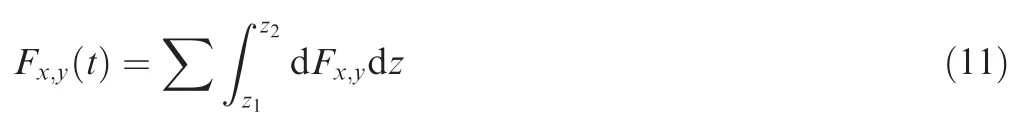
where z1and z2are the lower and upper axial engagement limits of the in-cut portion of the flute.To simulate the dynamic displacement,all initial conditions are set to zero at the beginning.For the first iterations,only cutting force will take effect.After that,the simulation begins to use previous solutions to calculate the dynamic displacement,and thus the vibration becomes effective.
A flowchart for the time-domain simulation of the cutter exit process is given in Fig.4.According to this flowchart,the dynamic cutting force and displacement for the cutter exit process can be simulated.
4.Experiments and discussion
To validate the developed model,both simulations and real cutting tests were carried out.The workpiece material was aluminum alloy,with a length of 63.2 mm.The cutter used was a four-flute end milling cutter with a diameter of 10 mm and a helix angle of 45°.Slot cutting was used in the tests.
To extract the milling system modal parameters,a hammer test was conducted first,as shown in Fig.5.The frequency response function(FRF)can be obtained from this test and then the modal parameters can be calibrated by utilizing the method proposed by Altintas1,which are listed in Table 1.
For the purpose of calibrating the cutting force coefficients,six slotting tests were carried out with 5000 r/min spindle speed and 3.0 mm axial depth of cut,while the feedrate was changed as50 mm/min,100 mm/min,150 mm/min,200 mm/min,250 mm/min,and 300 mm/min.Then the two following equations simplified by Altintas1were used in the calibration process:
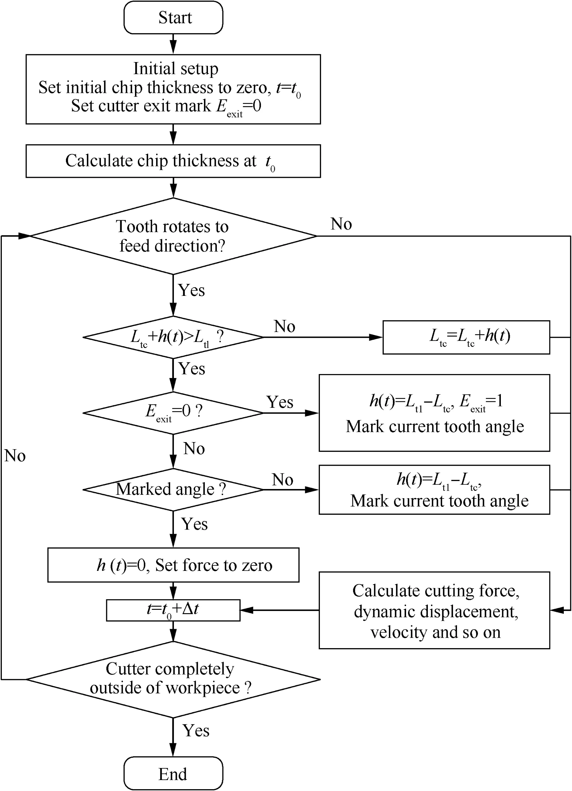
Fig.4 Flowchart for simulation of the cutter exit process.

Fig.5 Hammer test setup.
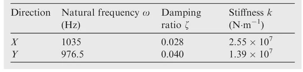
Table 1 Milling system parameters.
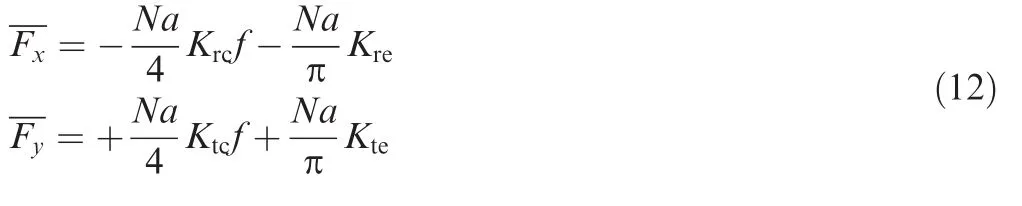
where FxandFyare the average forces per tooth period in the X and Y directions,respectively,N is the number of teeth,a is the axial depth of cut,and f is the feedrate per tooth.Therefore,based on the six slotting experimental forces results,the cutting force coefficients can be calibrated as Ktc=2.89×10⁸N/m2,Krc=2.14×108N/m2,Kte=1.29×104N/m,and Kre=9.64×10³N/m.
Stability lobes for the machining system are shown in Fig.6.Since this is a model for slot milling,the radial depth of cut cannot be changed during the validation,and different cutting parameters could be implemented into different spindle speeds,axial depths of cut,and feedrates.Hence,this paper selects two stable machining conditions from the stability lobes.For the first group,the spindle speed is 5000 r/min and the axial depth of cut is 3.0 mm,with a 300 mm/min feedrate.For the second group,the spindle speed is 4000 r/min and the axial depth of cut is 2.0 mm,with a 400 mm/min feedrate.The stars in Fig.6 show the two groups of machining conditions.Cutting forces during the milling process were recorded by a Kistler 9257B dynamometer,and the feed direction of slot milling was along the Y direction of the dynamometer.
Thesimulatedcuttingforcesinthetwodirectionsforthefirst group are shown in Fig.7(a)and(c),while the measured cutting forces are shown in Fig.7(b)and(d).The simulated cutting force in the X direction shows that the cutting force amplitude increases for a short time when the cutter is exiting the workpiece around 12.8 s;the measured cutting force given in Fig.7(b)also shows the same trend.The simulated cutting force in the Y direction decreases when the cutter is exiting the workpiece,with the measured cutting force showing the same trend(Fig.7(d))too.Both the simulated and measured cutting forces indicate that vibration happened when the cutter exited the workpiece,which lasted about one second.The vibration may be caused by the change of the dynamic chip thickness which disturbs the dynamic stability of the milling system.Besides,the impacts of the cutter tooth entering and exiting the workpiece may also have triggered the vibration of the cutter.
The simulated cutting forces for the second group in the two directions are shown in Fig.8(a)and(c),while the measured cutting forces are shown in Fig.8(b)and(d).The simulated and measured cutting forces show the same trend.
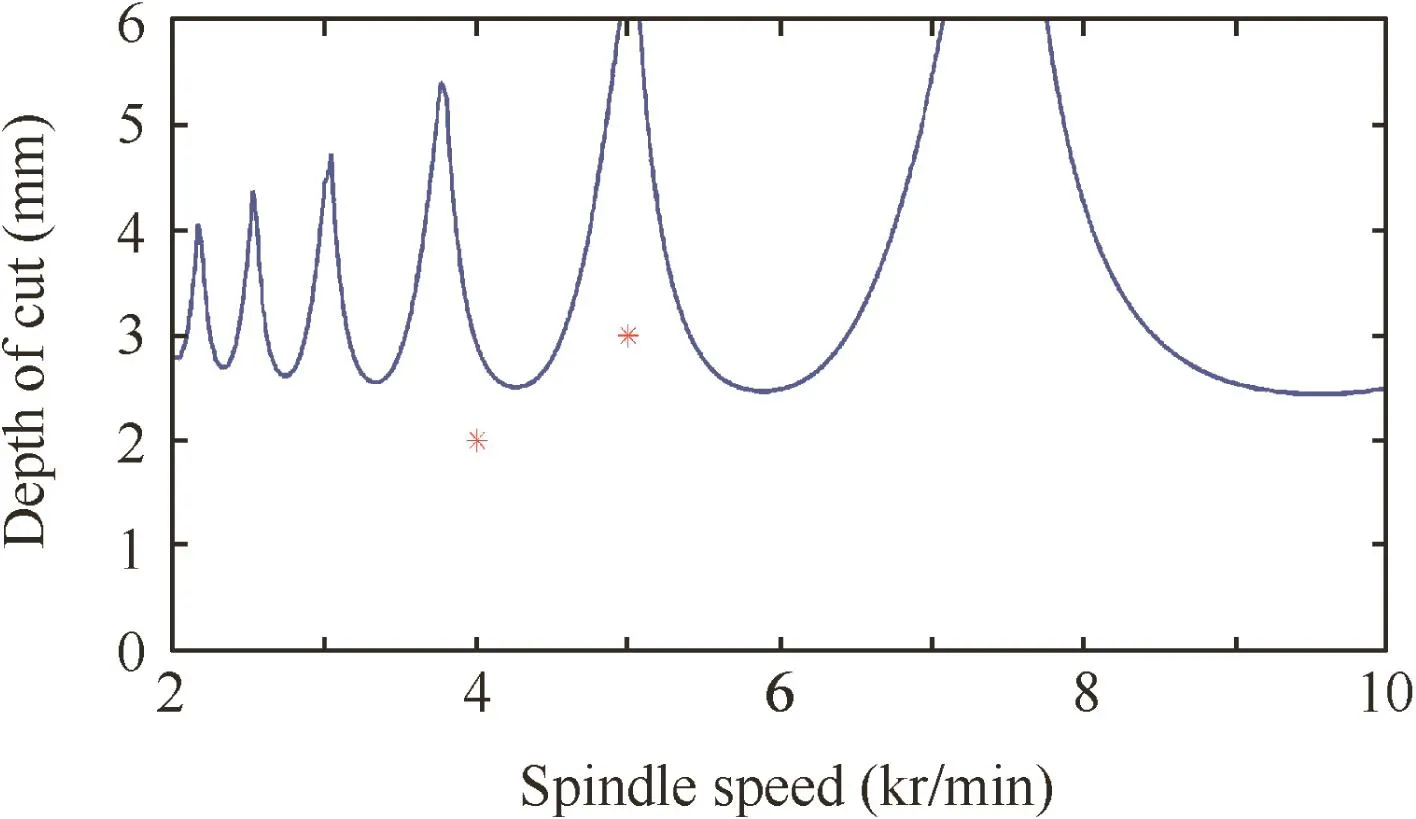
Fig.6 Stability lobes for the milling system with parameters in Table 1.
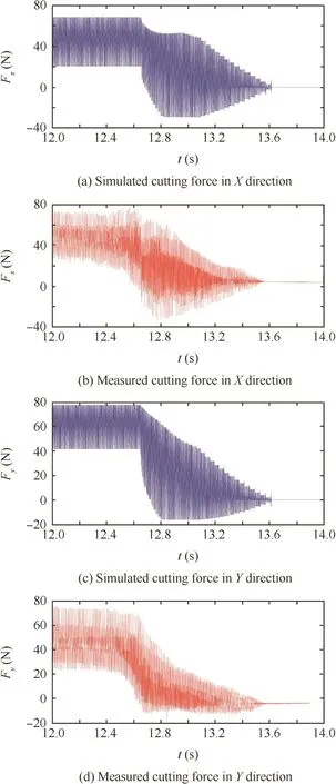
Fig.7 Simulated and measured cutting forces for the first group(5000 r/min).
From both the simulated and experimental data,it is obvious that during the cutter exit process,the cutting forces change heavily in a very short time range when compared with those in the normal cutting process,especially that the forces change their directions(which can be seen in the figure that some of the forces become negative in this process).Such a phenomenon results in vibration since during the normal cutting process,the forces are always positive and their values change in a pretty small range.However,in the cutter exit process,the forces change to negative suddenly and vary from positive to negative frequently.Additionally,the variance of their values is obviously larger than that in the normal process.Such a phenomenon makes the cutting system lose stability and results in vibration.Compared with experimental data,the simulation predicts such a big variance and the values of negative forces properly.Furthermore,in time domain,comparing the simulated and experimental forces,both of their values start to be negative around 12.7 s.
The real machining result for the first machining test shown in Fig.9 exhibits perceptible vibration marks left on the machined surface.Thus,the above analysis shows that the simulated results have a good agreement with those from the physical cutting experiment,which validates the effectiveness of the developed model.
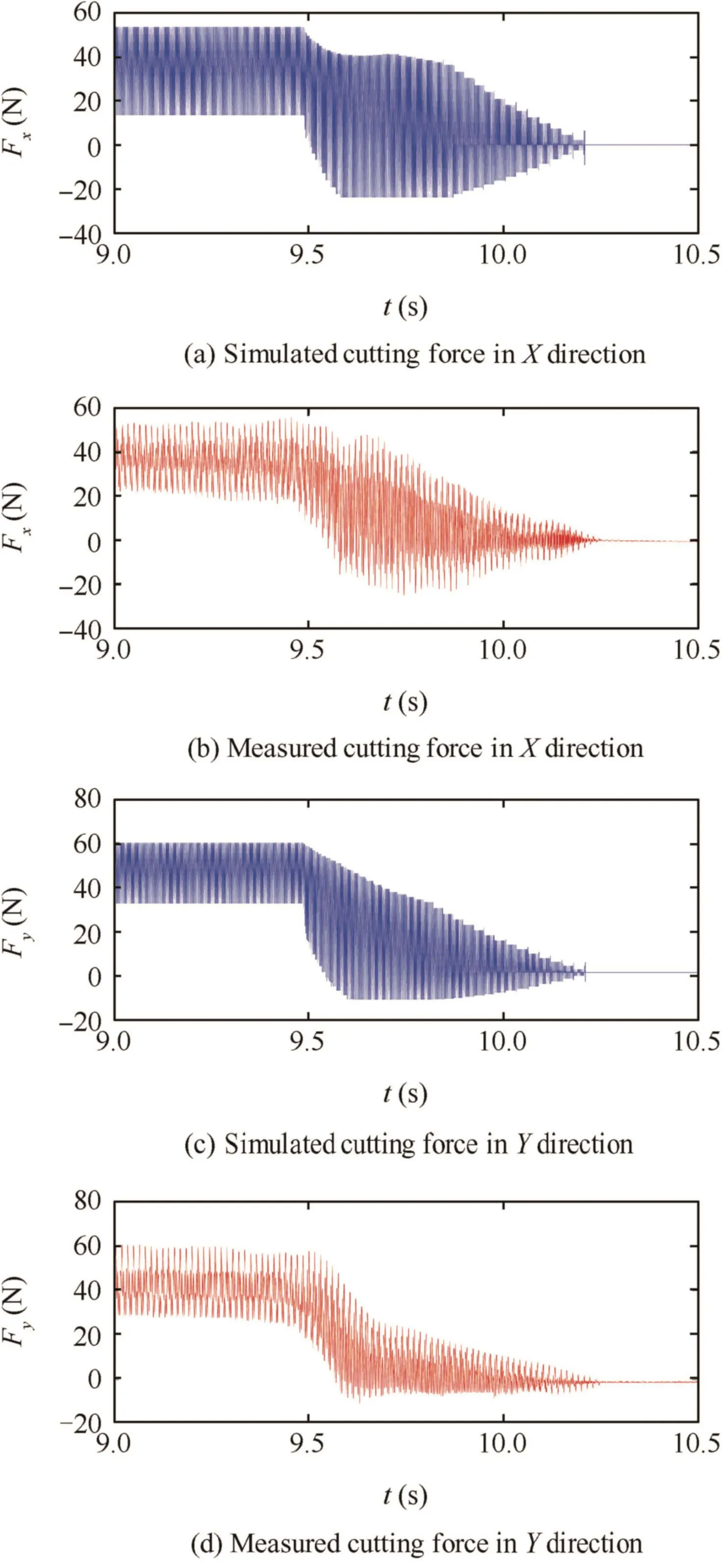
Fig.8 Simulated and measured cutting forces for the second group(4000 r/min).
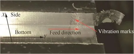
Fig.9 Machined result and vibration marks for the slot milling test.
5.Conclusions
(1)A new model in the time domain for a cutter exiting a workpiece in a milling process is presented.The developed model can help to understand the basic mechanics of the cutter exit process.
(2)The dynamic chip thickness is summed up along the feed direction and compared with the remaining workpiece length in the feed direction to judge whether the cutter is ready to exit the workpiece or not.
(3)Both simulation and experimental results reveal that vibration occurs when the cutter begins to exit the workpiece.It may be caused by the change of the dynamic chip thickness which disturbs the dynamic stability of the milling system.
(4)As a next step,it is planned to extend the developed model to machining cases with a small radial depth of cut.Furthermore,how to control the vibration for the cutter exit process will be studied and validated by real machining experiments.
Acknowledgments
This study was co-supported by the National Natural Science Foundation of China(Nos.51305354 and 51611130191),National Basic Research Program of China (No.2013CB035802),and the Fundamental Research Funds for the Central Universities(No.3102015JCS05002).
Appendix A.Supplementary material
Supplementary data associated with this article can be found,in the online version,at http://dx.doi.org/10.1016/j.cja.2016.10.014.
1.Altintas Y.Manufacturing automation:metal cutting mechanics,machine tool vibration,and CNC design.2nd ed.Cambridge,UK:Cambridge University Press;2012.
2.Quintana G,Ciurana J.Chatter in machining processes:a review.Int J Mach Tool Manu 2011;51(5):363–76.
3.Budak E.An analytical design method for milling cutters with nonconstant pitch to increase stability,part I:theory.J Manuf Sci E-T ASME 2003;125(2):29–34.
4.Luo M,Zhang DH,Wu BH,Zhou X.Material removal process optimization for milling offlexible workpiece considering machining stability.P I Mech Eng B-J Eng 2011;225(8):1263–72.
5.Taylor F.On the art of cutting metals.New York:American Society of Mechanical Engineers;1907.
6.Tobias S.Machine-tool vibration.New York:Wiley;1965.
7.Minis I,Yanushevsky R,Tembo A,Hocken R.Analysis of linear and nonlinear chatter in milling.CIRP Ann–Manuf Technol 1990;39(1):459–62.
8.Minis I,Yanushevsky R.A new theoretical approach for the prediction of machine tool chatter in milling.J Eng Ind 1993;115(1):1–8.
9.Altintas Y,Budak E.Analytical prediction of stability lobes in milling.CIRP Ann –Manuf Technol 1995;44(1):357–62.
10.Budak E,Altintas Y.Analytical prediction of chatter stability in milling—part II:application of the general formulation to common milling systems.J Dyn Sys Meas-T ASME 1998;120(1):31–6.
11.Insperger T,Ste′pa′n G.Semi-discretization method for delayed systems.Int J Numer Meth Eng 2002;55(5):503–18.
12.Meng H-F,Kang Y,Chen Z,Zhao YB,Liu GP.Stability analysis and stabilization of a class of cutting systems with chatter suppression.IEEE-ASME T Mech 2015;20(2):991–6.
13.Ding Y,Zhu L,Zhang X,Ding H.On a numerical method for simultaneous prediction of stability and surface location error in low radial immersion milling.J Dyn Sys Meas-T ASME 2011;133(2):024503–8.
14.Ding Y,Zhu L,Zhang X,Ding H.Numerical integration method for prediction of milling stability.J Manuf Sci E-T ASME 2011;133(3):031005–9.
15.Wu B,Yan X,Luo M,Gao G.Cutting force prediction for circularend milling process.Chinese J Aeronaut2013;26(4):1057–63.
16.Sun Y,Guo Q.Numerical simulation and prediction of cutting forces in five-axis milling processes with cutter run-out.Int J Mach Tool Manuf 2011;51(10–11):806–15.
17.Hashimura M,Hassamontr J,Dornfeld DA.Effect of in-plane exit angle and rake angles on burr height and thickness in face milling operation.J Manuf Sci E-T ASME 1999;121(1):13–9.
18.Aurich JC,Dornfeld D,Arrazola PJ,Franke V,Leitz L,Min S.Burrs-analysis,control and removal.CIRP Ann–Manuf Technol 2009;58(2):519–42.
19.Toh CK.A study of the effects of cutter path strategies and orientations in milling.J Mater Process Tech 2004;152(3):346–56.
20.Wanner B,Eynian M,Beno T,Pejryd L.Cutter exit effects during milling of thin-walled inconel 718. Adv Mater Res 2012;590:297–308.
21.Zhang X,Xiong C,Ding Y,Huang X,Ding H.A synthetical stability method for cutting parameter optimization to assure surface location accuracy in flexible part milling.Int J Adv Manuf Technol 2014;75(5):1131–47.
22.Altintas Y,Shamoto E,Lee P,Budak E.Analytical prediction of stability lobes in ball end milling.J Manuf Sci E-T ASME 1999;121(4):586–92.
23.Altintas■Y,Lee P.A general mechanics and dynamics model for helical end mills.CIRP Ann – Manuf Technol 1996;45(1):59–64.
Luo Ming received his Ph.D.degree in Advanced Manufacturing Engineering from Northwestern Polytechnical University in 2012.He is a junior research scientist in the Key Laboratory of Contemporary Design and Integrated Manufacturing Technology(Northwestern Polytechnical University),Ministry of Education.His main research interests are machining dynamics,machining process monitoring and optimization.
Mei Jiawei is a Ph.D.student at Northwestern Polytechnical University.He is a Marie Curie Early Stage Researcher in the Machining and Condition Monitoring Group at University of Nottingham from 2015 to 2016.His area of research includes machining dynamics and composite machining.
Zhang Dinghua is a professor and Ph.D.advisor in the Key Laboratory of Contemporary Design and Integrated Manufacturing Technology(Northwestern Polytechnical University),Ministry of Education.His current research interests are intelligent machining,non-destructive testing,and surface integrity.
26 May 2016;revised 21 July 2016;accepted 4 September 2016
Available online 21 October 2016
Cutting force;
Chip thickness;
Dynamic stability;
Machining;
Milling;
Vibration
?2016 Chinese Society of Aeronautics and Astronautics.Production and hosting by Elsevier Ltd.This is anopenaccessarticleundertheCCBY-NC-NDlicense(http://creativecommons.org/licenses/by-nc-nd/4.0/).
*Corresponding author.Tel.:+86 29 88493232 409.
E-mail address:luoming@nwpu.edu.cn(M.Luo).
Peer review under responsibility of Editorial Committee of CJA.
Production and hosting by Elsevier
http://dx.doi.org/10.1016/j.cja.2016.10.014
1000-9361?2016 Chinese Society of Aeronautics and Astronautics.Production and hosting by Elsevier Ltd.
This is an open access article under the CC BY-NC-ND license(http://creativecommons.org/licenses/by-nc-nd/4.0/).
 CHINESE JOURNAL OF AERONAUTICS2016年6期
- CHINESE JOURNAL OF AERONAUTICS的其它文章
- Algorithm and experiments of six-dimensional force/torque dynamic measurements based on a Stewart platform
- Type synthesis of 2-DoF rotational parallel mechanisms actuating the inter-satellite link antenna
- Comparison of alternative route selection strategies based on simulation optimization
- Cutting tool temperature prediction method using analytical model for end milling
- Plastic wrinkling model and characteristics of shear enforced Ti-alloy thin-walled tubes under combination die constraints and diff erential temperature fields
- Probability hypothesis density filter with adaptive parameter estimation for tracking multiple maneuvering targets